Configuring the System as a Standalone eGTP P-GW
This section provides a high-level series of steps and the associated configuration file examples for configuring the system to perform as an eGTP P-GW in a test environment. For a complete configuration file example, refer to the Sample Configuration Files appendix. Information provided in this section includes the following:
Information Required
The following sections describe the minimum amount of information required to configure and make the P-GW operational on the network. To make the process more efficient, it is recommended that this information be available prior to configuring the system.
There are additional configuration parameters that are not described in this section. These parameters deal mostly with fine-tuning the operation of the P-GW in the network. Information on these parameters can be found in the appropriate sections of the Command Line Interface Reference.
Required Local Context Configuration Information
The following table lists the information that is required to configure the local context on an P-GW.
| Required Information | Description | ||
|---|---|---|---|
|
Management Interface Configuration |
|||
|
Interface name |
An identification string between 1 and 79 characters (alpha and/or numeric) by which the interface will be recognized by the system. Multiple names are needed if multiple interfaces will be configured. |
||
|
IP address and subnet |
IPv4 addresses assigned to the interface. Multiple addresses and subnets are needed if multiple interfaces will be configured. |
||
|
Physical port number |
The physical port to which the interface will be bound. Ports are identified by the chassis slot number where the line card resides followed by the number of the physical connector on the card. For example, port 17/1 identifies connector number 1 on the card in slot 17. A single physical port can facilitate multiple interfaces. |
||
|
Gateway IP address |
Used when configuring static IP routes from the management interface(s) to a specific network. |
||
|
Security administrator name |
The name or names of the security administrator with full rights to the system. |
||
|
Security administrator password |
Open or encrypted passwords can be used. |
||
|
Remote access type(s) |
The type of remote access protocol that will be used to access the system, such as telnet, SSH, and/or FTP.
|
||
Required P-GW Context Configuration Information
The following table lists the information that is required to configure the P-GW context on a P-GW.
| Required Information | Description |
|---|---|
|
P-GW context name |
An identification string from 1 to 79 characters (alpha and/or numeric) by which the P-GW context will be recognized by the system. |
|
Accounting policy name |
An identification string from 1 to 63 characters (alpha and/or numeric) by which the accounting policy will be recognized by the system. The accounting policy is used to set parameters for the Rf (off-line charging) interface. |
|
S5/S8 Interface Configuration (To/from S-GW) |
|
|
Interface name |
An identification string between 1 and 79 characters (alpha and/or numeric) by which the interface will be recognized by the system. Multiple names are needed if multiple interfaces will be configured. |
|
IP address and subnet |
IPv4 or IPv6 addresses assigned to the interface. Multiple addresses and subnets are needed if multiple interfaces will be configured. |
|
Physical port number |
The physical port to which the interface will be bound. Ports are identified by the chassis slot number where the line card resides followed by the number of the physical connector on the card. For example, port 17/1 identifies connector number 1 on the card in slot 17. A single physical port can facilitate multiple interfaces. |
|
Gateway IP address |
Used when configuring static IP routes from the interface(s) to a specific network. |
|
GTP-U Service Configuration |
|
|
GTP-U service name |
An identification string from 1 to 63 characters (alpha and/or numeric) by which the GTP-U service will be recognized by the system. |
|
IP address |
S5/S8 interface IPv4 address. |
|
P-GW Service Configuration |
|
|
P-GW service name |
An identification string from 1 to 63 characters (alpha and/or numeric) by which the P-GW service will be recognized by the system. Multiple names are needed if multiple P-GW services will be used. |
|
PLMN ID |
MCC number: The mobile country code (MCC) portion of the PLMN's identifier (an integer value between 100 and 999). MNC number: The mobile network code (MNC) portion of the PLMN's identifier (a 2 or 3 digit integer value between 00 and 999). |
|
eGTP Service Configuration |
|
|
eGTP Service Name |
An identification string from 1 to 63 characters (alpha and/or numeric) by which the eGTP service will be recognized by the system. |
Required PDN Context Configuration Information
The following table lists the information that is required to configure the PDN context on a P-GW.
| Required Information | Description |
|---|---|
|
PDN context name |
An identification string from 1 to 79 characters (alpha and/or numeric) by which the PDN context is recognized by the system. |
|
IP Address Pool Configuration |
|
|
IPv4 address pool name and range |
An identification string between 1 and 31 characters (alpha and/or numeric) by which the IPv4 pool is recognized by the system. Multiple names are needed if multiple pools will be configured. A range of IPv4 addresses defined by a starting address and an ending address. |
|
IPv6 address pool name and range |
An identification string between 1 and 31 characters (alpha and/or numeric) by which the IPv6 pool is recognized by the system. Multiple names are needed if multiple pools will be configured. A range of IPv6 addresses defined by a starting address and an ending address. |
|
Access Control List Configuration |
|
|
IPv4 access list name |
An identification string between 1 and 47 characters (alpha and/or numeric) by which the IPv4 access list is recognized by the system. Multiple names are needed if multiple lists will be configured. |
|
IPv6 access list name |
An identification string between 1 and 79 characters (alpha and/or numeric) by which the IPv6 access list is recognized by the system. Multiple names are needed if multiple lists will be configured. |
|
Deny/permit type |
|
|
Readdress or redirect type |
|
|
SGi Interface Configuration (To/from IPv4 PDN) |
|
|
Interface name |
An identification string between 1 and 79 characters (alpha and/or numeric) by which the interface is recognized by the system. Multiple names are needed if multiple interfaces will be configured. |
|
IP address and subnet |
IPv4 addresses assigned to the interface. Multiple addresses and subnets are needed if multiple interfaces will be configured. |
|
Physical port number |
The physical port to which the interface will be bound. Ports are identified by the chassis slot number where the line card resides followed by the number of the physical connector on the card. For example, port 17/1 identifies connector number 1 on the card in slot 17. A single physical port can facilitate multiple interfaces. |
|
Gateway IP address |
Used when configuring static IP routes from the interface(s) to a specific network. |
|
SGi Interface Configuration (To/from IPv6 PDN) |
|
|
Interface name |
An identification string between 1 and 79 characters (alpha and/or numeric) by which the interface is recognized by the system. Multiple names are needed if multiple interfaces will be configured. |
|
IP address and subnet |
IPv6 addresses assigned to the interface. Multiple addresses and subnets are needed if multiple interfaces will be configured. |
|
Physical port number |
The physical port to which the interface will be bound. Ports are identified by the chassis slot number where the line card resides followed by the number of the physical connector on the card. For example, port 17/1 identifies connector number 1 on the card in slot 17. A single physical port can facilitate multiple interfaces. |
|
Gateway IP address |
Used when configuring static IP routes from the interface(s) to a specific network. |
Required AAA Context Configuration Information
The following table lists the information that is required to configure the AAA context on a P-GW.
| Required Information | Description |
|---|---|
|
Gx Interface Configuration (to PCRF) |
|
|
Interface name |
An identification string between 1 and 79 characters (alpha and/or numeric) by which the interface is recognized by the system. Multiple names are needed if multiple interfaces will be configured. |
|
IP address and subnet |
IPv4 or IPv6 addresses assigned to the interface. Multiple addresses and subnets are needed if multiple interfaces will be configured. |
|
Physical port number |
The physical port to which the interface will be bound. Ports are identified by the chassis slot number where the line card resides followed by the number of the physical connector on the card. For example, port 17/1 identifies connector number 1 on the card in slot 17. A single physical port can facilitate multiple interfaces. |
|
Gateway IP address |
Used when configuring static IP routes from the interface(s) to a specific network. |
|
Gx Diameter Endpoint Configuration |
|
|
End point name |
An identification string from 1 to 63 characters (alpha and/or numeric) by which the Gx Diameter endpoint configuration is recognized by the system. |
|
Origin realm name |
An identification string between 1 through 127 characters. The realm is the Diameter identity. The originator's realm is present in all Diameter messages and is typically the company or service name. |
|
Origin host name |
An identification string from 1 to 255 characters (alpha and/or numeric) by which the Gx origin host is recognized by the system. |
|
Origin host address |
The IP address of the Gx interface. |
|
Peer name |
The Gx endpoint name described above. |
|
Peer realm name |
The Gx origin realm name described above. |
|
Peer address and port number |
The IP address and port number of the PCRF. |
|
Route-entry peer |
The Gx endpoint name described above. |
|
Gy Interface Configuration (to on-line charging server) |
|
|
Interface name |
An identification string between 1 and 79 characters (alpha and/or numeric) by which the interface is recognized by the system. Multiple names are needed if multiple interfaces will be configured. |
|
IP address and subnet |
IPv4 or IPv6 addresses assigned to the interface. Multiple addresses and subnets are needed if multiple interfaces will be configured. |
|
Physical port number |
The physical port to which the interface will be bound. Ports are identified by the chassis slot number where the line card resides followed by the number of the physical connector on the card. For example, port 17/1 identifies connector number 1 on the card in slot 17. A single physical port can facilitate multiple interfaces. |
|
Gateway IP address |
Used when configuring static IP routes from the interface(s) to a specific network. |
|
Gy Diameter Endpoint Configuration |
|
|
End point name |
An identification string from 1 to 63 characters (alpha and/or numeric) by which the Gy Diameter endpoint configuration is recognized by the system. |
|
Origin realm name |
An identification string between 1 through 127 characters. The realm is the Diameter identity. The originator's realm is present in all Diameter messages and is typically the company or service name. |
|
Origin host name |
An identification string from 1 to 255 characters (alpha and/or numeric) by which the Gy origin host is recognized by the system. |
|
Origin host address |
The IP address of the Gy interface. |
|
Peer name |
The Gy endpoint name described above. |
|
Peer realm name |
The Gy origin realm name described above. |
|
Peer address and port number |
The IP address and port number of the OCS. |
|
Route-entry peer |
The Gy endpoint name described above. |
|
Gz Interface Configuration (to off-line charging server) |
|
|
Interface name |
An identification string between 1 and 79 characters (alpha and/or numeric) by which the interface is recognized by the system. Multiple names are needed if multiple interfaces will be configured. |
|
IP address and subnet |
IPv4 addresses assigned to the interface. Multiple addresses and subnets are needed if multiple interfaces will be configured. |
|
Physical port number |
The physical port to which the interface will be bound. Ports are identified by the chassis slot number where the line card resides followed by the number of the physical connector on the card. For example, port 17/1 identifies connector number 1 on the card in slot 17. A single physical port can facilitate multiple interfaces. |
|
Gateway IP address |
Used when configuring static IP routes from the interface(s) to a specific network. |
|
Rf Interface Configuration (to off-line charging server) |
|
|
Interface name |
An identification string between 1 and 79 characters (alpha and/or numeric) by which the interface is recognized by the system. Multiple names are needed if multiple interfaces will be configured. |
|
IP address and subnet |
IPv4 or IPv6 addresses assigned to the interface. Multiple addresses and subnets are needed if multiple interfaces will be configured. |
|
Physical port number |
The physical port to which the interface will be bound. Ports are identified by the chassis slot number where the line card resides followed by the number of the physical connector on the card. For example, port 17/1 identifies connector number 1 on the card in slot 17. A single physical port can facilitate multiple interfaces. |
|
Gateway IP address |
Used when configuring static IP routes from the interface(s) to a specific network. |
|
Rf Diameter Endpoint Configuration |
|
|
End point name |
An identification string from 1 to 63 characters (alpha and/or numeric) by which the Rf Diameter endpoint configuration is recognized by the system. |
|
Origin realm name |
An identification string between 1 through 127 characters. The realm is the Diameter identity. The originator's realm is present in all Diameter messages and is typically the company or service name. |
|
Origin host name |
An identification string from 1 to 255 characters (alpha and/or numeric) by which the Rf origin host is recognized by the system. |
|
Origin host address |
The IP address of the Rf interface. |
|
Peer name |
The Rf endpoint name described above. |
|
Peer realm name |
The Rf origin realm name described above. |
|
Peer address and port number |
The IP address and port number of the OFCS. |
|
Route-entry peer |
The Rf endpoint name described above. |
How This Configuration Works
The following figure and supporting text describe how this configuration with a single source and destination context is used by the system to process a subscriber call originating from the GTP LTE network.
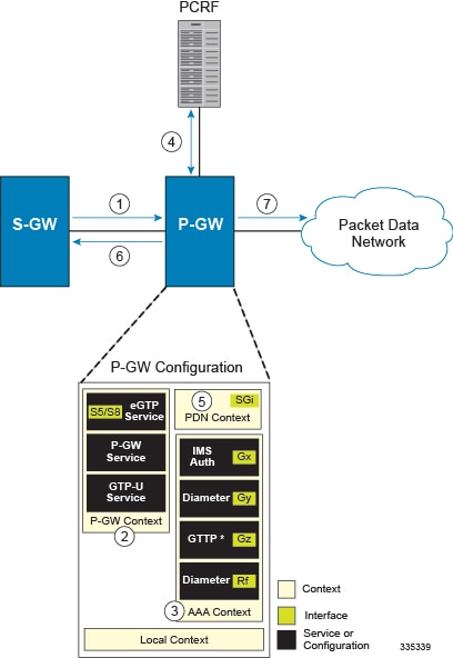
-
The S-GW establishes the S5/S8 connection by sending a Create Session Request message to the P-GW including an Access Point name (APN).
-
The P-GW service determines which context to use to provide AAA functionality for the session. This process is described in the How the System Selects Contexts section located in the Understanding the System Operation and Configuration chapter of the System Administration Guide.
-
The P-GW uses the configured Gx Diameter endpoint to establish the IP-CAN session.
-
The P-GW sends a CC-Request (CCR) message to the PCRF to indicate the establishment of the IP-CAN session and the PCRF acknowledges with a CC-Answer (CCA).
-
The P-GW uses the APN configuration to select the PDN context. IP addresses are assigned from the IP pool configured in the selected PDN context.
-
The P-GW responds to the S-GW with a Create Session Response message including the assigned address and additional information.
-
The S5/S8 data plane tunnel is established and the P-GW can forward and receive packets to/from the PDN.
eGTP P-GW Configuration
To configure the system to perform as a standalone eGTP P-GW:
Procedure
| Step 1 |
Set system configuration parameters such as activating PSCs by applying the example configurations found in the System Administration Guide. |
| Step 2 |
Set initial configuration parameters such as creating contexts and services by applying the example configurations found in the Initial Configuration. |
| Step 3 |
Configure the system to perform as an eGTP P-GW and set basic P-GW parameters such as eGTP interfaces and IP routes by applying the example configurations presented in the P-GW Service Configuration. |
| Step 4 |
Configure the PDN context by applying the example configuration in the P-GW PDN Context Configuration. |
| Step 5 |
Enable and configure the active charging service for Gx interface support by applying the example configuration in the Active Charging Service Configuration. |
| Step 6 |
Create a AAA context and configure parameters for policy by applying the example configuration in the Policy Configuration. |
| Step 7 |
Verify and save the configuration by following the steps found in Verifying and Saving the Configuration. |
Initial Configuration
Procedure
| Step 1 |
Set local system management parameters by applying the example configuration in Modifying the Local Context. |
| Step 2 |
Create the context where the eGTP service will reside by applying the example configuration in Creating and Configuring an eGTP P-GW Context. |
| Step 3 |
Create and configure APNs in the P-GW context by applying the example configuration in Creating and Configuring APNs in the P-GW Context. |
| Step 4 |
Create and configure AAA server groups in the P-GW context by applying the example configuration in Creating and Configuring AAA Groups in the P-GW Context. |
| Step 5 |
Create an eGTP service within the newly created context by applying the example configuration in Creating and Configuring an eGTP Service. |
| Step 6 |
Create and configure a GTP-U service within the P-GW context by applying the example configuration in Creating and Configuring a GTP-U Service. |
| Step 7 |
Create a context through which the interface to the PDN will reside by applying the example configuration in Creating a P-GW PDN Context. |
Modifying the Local Context
Use the following example to set the default subscriber and configure remote access capability in the local context:
configure
   context local
      interface  <lcl_cntxt_intrfc_name>
         ip address  <ip_address> <ip_mask>
            exit
         server ftpd
            exit
         server telnetd
            exit
         subscriber default
            exit
         administrator  <name> encrypted password  <password> ftp
         ip route  <ip_addr/ip_mask> <next_hop_addr> <lcl_cntxt_intrfc_name>
         exit
   port ethernet  <slot#/port#>
      no shutdown
      bind interface  <lcl_cntxt_intrfc_name> local
      end
Creating and Configuring an eGTP P-GW Context
Use the following example to create a P-GW context, create an S5/S8 IPv4 interface (for data traffic to/from the S-GW), and bind the S5/S8 interface to a configured Ethernet port:
configure
   gtpp single-source
   context  <pgw_context_name> -noconfirm
      interface  <s5s8_interface_name>
         ip address  <ipv4_address>
         exit
      gtpp group default
         gtpp charging-agent address  <gz_ipv4_address>
         gtpp echo-interval  <seconds>
         gtpp attribute diagnostics
         gtpp attribute local-record-sequence-number
         gtpp attribute node-id-suffix  <string>
         gtpp dictionary  <name>
         gtpp server  <ipv4_address> priority  <num>
         gtpp server  <ipv4_address> priority <num> node-alive enable
         exit
      policy accounting  <rf_policy_name> -noconfirm
         accounting-level  {level_type}
         accounting-event-trigger interim-timeout action stop-star t
         operator-string  <string>
         cc profile  <index> interval  <seconds>
         exit
      exit
   subscriber default
      exit
   port ethernet  <slot_number/port_number>
      no shutdown
      bind interface  <s5s8_interface_name> <pgw_context_name>
      end
Notes:
-
gtpp single-source is enabled to allow the system to generate requests to the accounting server using a single UDP port (by way of a AAA proxy function) rather than each AAA manager generating requests on unique UDP ports.
-
The S5/S8 (P-GW to S-GW) interface IP address can also be specified as an IPv6 address using the ipv6 address command.
-
Set the accounting policy for the Rf (off-line charging) interface. The accounting level types are: flow, PDN, PDN-QCI, QCI, and subscriber. Refer to the Accounting Profile Configuration Mode Commands chapter in the Command Line Interface Reference for more information on this command.
-
Set the GTPP group setting for Gz accounting.
Creating and Configuring APNs in the P-GW Context
Use the following configuration to create an APN:
configure
   context  <pgw_context_name> -noconfirm
      apn  <name>
         accounting-mode radius-diameter
         associate accounting-policy  <rf_policy_name>
         ims-auth-service  <gx_ims_service_name>
         aaa group  <rf-radius_group_name>
         dns primary  <ipv4_address>
         dns secondary  <ipv4_address>
         ip access-group  <name> in
         ip access-group  <name> out
         mediation-device context-name  <pgw_context_name>
         ip context-name  <pdn_context_name>
         ipv6 access-group  <name> in
         ipv6 access-group  <name> out
         active-charging rulebase  <name>
         end
Notes:
-
The IMS Authorization Service is created and configured in the AAA context.
-
Multiple APNs can be configured to support different domain names.
-
The associate accounting-policy command is used to associate a pre-configured accounting policy with this APN. Accounting policies are configured in the P-GW context. An example is located in the Creating and Configuring an eGTP P-GW Context.
Use the following configuration to create an APN that includes Gz interface parameters:
configure
   context  <pgw_context_name> -noconfirm
      apn  <name>
         bearer-control-mode mixed
         selection-mode sent-by-ms
         accounting-mode gtpp
         gtpp group default accounting-context  <aaa_context_name>
         ims-auth-service  <gx_ims_service_name>
         ip access-group  <name> in
         ip access-group  <name> out
         ip context-name  <pdn_context_name>
         active-charging rulebase  <gz_rulebase_name>
         end
Notes:
-
The IMS Authorization Service is created and configured in the AAA context.
-
Multiple APNs can be configured to support different domain names.
-
The accounting-mode GTPP and GTPP group commands configure this APN for Gz accounting.
Creating and Configuring AAA Groups in the P-GW Context
Use the following example to create and configure AAA groups supporting RADIUS and Rf accounting:
configure
   context  <pgw_context_name> -noconfirm
      aaa group  <rf-radius_group_name>
         radius attribute nas-identifier  <id>
         radius accounting interim interval  <seconds>
         radius dictionary  <name>
         radius mediation-device accounting server  <address> key  <key>
         diameter authentication dictionary  <name>
         diameter accounting dictionary  <name>
         diameter accounting endpoint  <rf_cfg_name>
         diameter accounting server  <rf_cfg_name> priority  <num>
         exit
      aaa group default
         radius attribute nas-ip-address address  <ipv4_address>
         radius accounting interim interval  <seconds>
         diameter authentication dictionary  <name>
         diameter accounting dictionary  <name>
         diameter accounting endpoint  <rf_cfg_name>
         diameter accounting server  <rf_cfg_name> priority  <num>
         end
Creating and Configuring an eGTP Service
Use the following configuration example to create the eGTP service:
configure
   context  <pgw_context_name>
      egtp-service  <egtp_service_name> -noconfirm
         interface-type interface-pgw-ingress
         validation mode default
         associate gtpu-service  <gtpu_service_name>
         gtpc bind address  <s5s8_interface_address>
         end
Notes:
-
Co-locating a P-GW service on the same ASR 5500 requires that the gtpc bind address command uses the same IP address the P-GW service is bound to.
Creating and Configuring a GTP-U Service
Use the following configuration example to create the GTP-U service:
configure
   context  <pgw_context_name>
      gtpu-service  <gtpu_service_name> -noconfirm
         bind ipv4-address  <s5s8_interface_address>
         end
Notes:
-
The bind command can also be specified as an IPv6 address using the ipv6-address command.
Creating a P-GW PDN Context
Use the following example to create a P-GW PDN context and Ethernet interface, and bind the interface to a configured Ethernet port.
configure
   context  <pdn_context_name> -noconfirm
      interface  <sgi_ipv4_interface_name>
         ip address  <ipv4_address>
      interface  <sgi_ipv6_interface_name>
         ipv6 address  <address>
         end
P-GW Service Configuration
Procedure
| Step 1 |
Configure the P-GW service by applying the example configuration in the Configuring the P-GW Service. |
| Step 2 |
Specify an IP route to the eGTP Serving Gateway by applying the example configuration in the Configuring a Static IP Route. |
Configuring the P-GW Service
Use the following example to configure the P-GW service:
configure
   context  <pgw_context_name>
      pgw-service  <pgw_service_name> -noconfirm
            plmn id mcc  <id> mnc  <id>
            associate egtp-service  <egtp_service_name>
            associate qci-qos-mapping  <name>
            end
Notes:
-
QCI-QoS mapping configurations are created in the AAA context. Refer to the Configuring QCI-QoS Mapping for more information.
- Co-locating a P-GW service on the same ASR 5500 requires the configuration of the associate pgw-service name command within the P-GW service.
Configuring a Static IP Route
Use the following example to configure an IP Route for control and user plane data communication with an eGTP Serving Gateway:
configure
   context  <pgw_context_name>
      ip route  <sgw_ip_addr/mask> <sgw_next_hop_addr> <pgw_intrfc_name>
      end
P-GW PDN Context Configuration
Use the following example to configure an IP Pool and APN, and bind a port to the interface in the PDN context:
configure
   context  <pdn_context_name> -noconfirm
      interface  <sgi_ipv4_interface_name>
         ip address  <ipv4_address>
         exit
      interface  <sgi_ipv6_interface_name>
         ip address  <ipv6_address>
         exit
      ip pool  <name> range  <start_address end_address> public  <priority>
      ipv6 pool  <name> range  <start_address end_address> public  <priority>
      subscriber default
         exit
      ip access-list  <name>
         redirect css service  <name> any
         permit any
         exit
      ipv6 access-list  <name>
         redirect css service  <name> any
         permit any
         exit
         aaa group default
         exit
      exit
   port ethernet  <slot_number/port_number>
      no shutdown
      bind interface  <sgi_ipv4_interface_name> <pdn_context_name>
      exit
   port ethernet  <slot_number/port_number>
      no shutdown
      bind interface  <sgi_ipv6_interface_name> <pdn_context_name>
      end
Active Charging Service Configuration
Use the following example to enable and configure active charging:
configure
   require active-charging optimized-mode
   active-charging service < name>
      ruledef < name>
         < rule>
            .
            .
         < rule>
         exit
      ruledef default
         ip any-match = TRUE
         exit
      ruledef  icmp-pkts
         icmp any-match = TRUE
         exit
      ruledef  qci3
          icmp any-match = TRUE
         exit
      ruledef  static
         icmp any-match = TRUE
         exit
      charging-action < name>
         < action>
            .
            .
         < action>
         exit
      charging-action  icmp
         billing-action egcdr
         exit
      charging-action  qci3
         content-id < id>
         billing-action rf
         qos-class-identifier < id>
         allocation-retention-priority < priority>
         tft packet-filter  qci3
         exit
      charging-action  static
         service-identifier < id>
         billing-action rf
         qos-class-identifier < id>
         allocation-retention-priority < priority>
         tft packet-filter  qci3
         exit
      packet-filter < packet_filter_name>
         ip remote-address = { < ipv4/ipv6_address> | < ipv4/ipv6_address/mask> }
         ip remote-port { = < port_number> | range < start_port_number> to < end_port_number> }
         exit
      rulebase default
                  exit
      rulebase < name>
         < rule_base>
            .
            .
         < rule_base>
         exit
      rulebase < gx_rulebase_name>
         dynamic-rule order first-if-tied
         egcdr tariff minute < minute> hour < hour>(optional)
         billing-records egcdr
         action priority  5 dynamic-only ruledef  qci3 charging-action  qci3
         action priority  100 ruledef  static charging-action  static
         action priority  500 ruledef default charging-action  icmp
         action priority  570 ruledef  icmp-pkts charging-action  icmp
         egcdr threshold interval < interval>
         egcdr threshold volume total < bytes>
         end
Notes:
-
A rulebase is a collection of rule definitions and associated charging actions.
-
As depicted above, multiple rule definitions, charging actions, and rule bases can be configured to support a variety of charging scenarios.
-
Charging actions define the action to take when a rule definition is matched.
-
Routing and/or charging rule definitions can be created/configured. The maximum number of routing rule definitions that can be created is 256. The maximum number of charging rule definitions is 2048.
-
The billing-action egcdr command in the charging-action qc13 , icmp , and static examples is required for Gz accounting.
-
The Gz rulebase example supports the Gz interface for offline charging. The billing-records egcdr command is required for Gz accounting. All other commands are optional.
 Important |
If uplink packet is coming on the dedicated bearer, only rules installed on the dedicated bearer are matched. Static rules are not matched and packets failing to match the same will be dropped. |
Policy Configuration
Procedure
| Step 1 |
Configure the policy and accounting interfaces by applying the example configuration in the Creating and Configuring the AAA Context. |
| Step 2 |
Create and configure QCI to QoS mapping by applying the example configuration in the Configuring QCI-QoS Mapping. |
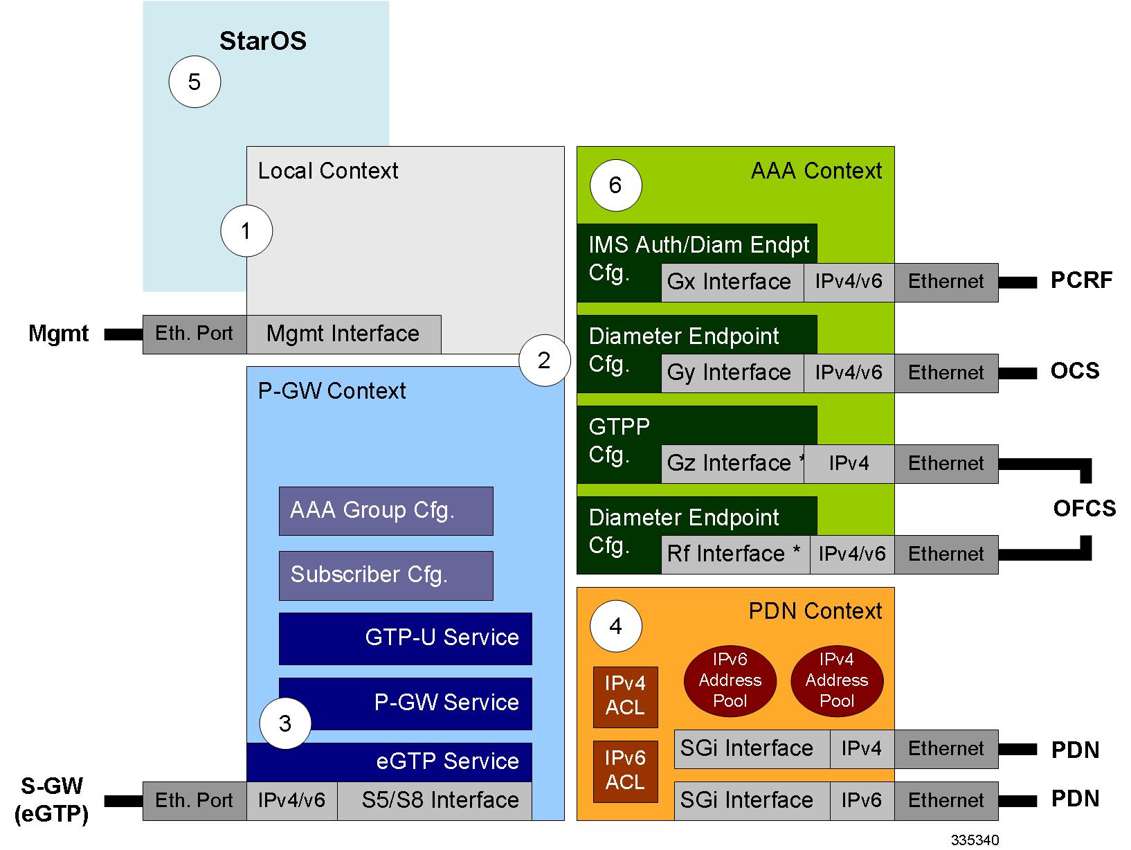
Creating and Configuring the AAA Context
Use the following example to create and configure a AAA context including diameter support and policy control, and bind Ethernet ports to interfaces supporting traffic between this context and a PCRF, an OCS, and an OFCS:
configure
   context  <aaa_context_name> -noconfirm
      interface  <gx_interface_name>
         ipv6 address  <address>
         exit
      interface  <gy_interface_name>
         ipv6 address  <address>
         exit
      interface  <gz_interface_name>
         ip address  <ipv4_address>
         exit
      interface  <rf_interface_name>
         ip address  <ipv4_address>
         exit
      subscriber default
         exit
      ims-auth-service  <gx_ims_service_name>
         p-cscf discovery table  <#> algorithm round-robin
         p-cscf table  <#> row-precedence  <#> ipv6-address  <pcrf_ipv6_adr>
         policy-control
            diameter origin endpoint  <gx_cfg_name>
            diameter dictionary  <name>
            diameter host-select table  <#> algorithm round-robin
            diameter host-select row-precedence  <#> table  <#> host  <gx_cfg_name>
            exit
         exit
      diameter endpoint  <gx_cfg_name>
         origin realm  <realm_name>
         origin host  <name> address  <aaa_ctx_ipv6_address>
         peer  <gx_cfg_name> realm  <name> address  <pcrf_ipv4_or_ipv6_addr>
         route-entry peer  <gx_cfg_name>
         exit
      diameter endpoint  <gy_cfg_name>
         origin realm  <realm_name>
         origin host  <name> address  <gy_ipv6_address>
         connection retry-timeout  <seconds>
         peer  <gy_cfg_name> realm <name> address  <ocs_ipv4_or_ipv6_addr>
         route-entry peer  <gy_cfg_name>
         exit
      diameter endpoint  <rf_cfg_name>
         use-proxy
         origin realm  <realm_name>
         origin host  <name> address  <rf_ipv4_address>
         peer  <rf_cfg_name> realm  <name> address  <ofcs_ipv4_or_ipv6_addr>
         route-entry peer  <rf_cfg_name>
         exit
      exit
   port ethernet  <slot_number/port_number>
      no shutdown
      bind interface  <gx_interface_name> <aaa_context_name>
      exit
   port ethernet  <slot_number/port_number>
      no shutdown
      bind interface  <gy_interface_name> <aaa_context_name>
      exit
   port ethernet  <slot_number/port_number>
      no shutdown
      bind interface  <gz_interface_name> <aaa_context_name>
      exit
   port ethernet  <slot_number/port_number>
      no shutdown
      bind interface  <rf_interface_name> <aaa_context_name>
      end
Notes:
-
The p-cscf table command under ims-auth-service can also specify an IPv4 address to the PCRF.
-
The Gx interface IP address can also be specified as an IPv4 address using the ip address command.
-
The Gy interface IP address can also be specified as an IPv4 address using the ip address command.
-
The Rf interface IP address can also be specified as an IPv6 address using the ipv6 address command.
Configuring QCI-QoS Mapping
Use the following example to create and map QCI values to enforceable QoS parameters:
configure
   qci-qos-mapping < name>
      qci 1 user-datagram dscp-marking < hex>
      qci 3 user-datagram dscp-marking < hex>
      qci 9 user-datagram dscp-marking < hex>
      end
Notes:
-
The P-GW does not support non-standard QCI values unless a valid license key is installed.
QCI values 1 through 9 are standard values defined in 3GPP TS 23.203; the P-GW supports these standard values.
From 3GPP Release 8 onwards, operator-specific/non-standard QCIs can be supported and carriers can define QCI 128- 254.
-
The above configuration only shows one keyword example. Refer to the QCI - QOS Mapping Configuration Mode Commands chapter in the Command Line Interface Reference for more information on the qci command and other supported keywords.
Verifying and Saving the Configuration
Save your configuration to flash memory, an external memory device, and/or a network location using the Exec mode command save configuration . For additional information on how to verify and save configuration files, refer to the System Administration Guide and the Command Line Interface Reference.
DHCP Service Configuration
The system can be configured to use the Dynamic Host Control Protocol (DHCP) to assign IP addresses for PDP contexts. IP address assignment using DHCP is done using the following method, as configured within an APN:
DHCP-proxy: The system acts as a proxy for client (MS) and initiates the DHCP Discovery Request on behalf of client (MS). Once it receives an allocated IP address from DHCP server in response to DHCP Discovery Request, it assigns the received IP address to the MS. This allocated address must be matched with the an address configured in an IP address pool on the system. This complete procedure is not visible to MS.
As the number of addresses in memory decreases, the system solicits additional addresses from the DHCP server. If the number of addresses stored in memory rises above the configured limit, they are released back to the DHCP server.
There are parameters that must first be configured that specify the DHCP servers to communicate with and how the IP address are handled. These parameters are configured as part of a DHCP service.
Important |
This section provides the minimum instruction set for configuring a DHCP service on system for DHCP-based IP allocation. For more information on commands that configure additional DHCP server parameters and working of these commands, refer to the DHCP Service Configuration Mode Commands chapter of Command Line Interface Reference. |
These instructions assume that you have already configured the system level configuration as described in System Administration Guide and P-GW service as described in eGTP P-GW Configuration section of this chapter.
To configure the DHCP service:
Procedure
| Step 1 |
Create the DHCP service in system context and bind it by applying the example configuration in the DHCP Service Creation. |
| Step 2 |
Configure the DHCP servers and minimum and maximum allowable lease times that are accepted in responses from DHCP servers by applying the example configuration in the DHCP Server Parameter Configuration. |
| Step 3 |
Verify your DHCP Service configuration by following the steps in the DHCPv6 Service Configuration Verification. |
| Step 4 |
Save your configuration as described in the Verifying and Saving Your Configuration section. |
DHCP Service Creation
Use the following example to create the DHCP service to support DHCP-based address assignment:
configure
   context  <dest_ctxt_name>
      dhcp-service  <dhcp_svc_name>
         bind address  <ip_address> [nexthop-forwarding-address  <nexthop_ip_address> [ mpls-label input  <in_mpls_label_value> output  <out_mpls_label_value1> [ out_mpls_label_value2]]]
end -
To ensure proper operation, DHCP functionality should be configured within a destination context.
-
Optional keyword nexthop-forwarding-address <nexthop_ip_address > [mpls-label input <in_mpls_label_value > output <out_mpls_label_value1 > [ out_mpls_label_value2 ]] applies DHCP over MPLS traffic.
DHCP Server Parameter Configuration
Use the following example to configure the DHCP server parameters to support DHCP-based address assignment:
configure
   context  <dest_ctxt_name>
      dhcp-service  <dhcp_svc_name>
         dhcp server  <ip_address> [priority  <priority>
         dhcp server selection-algorithm  {first-server | round-robin}
         lease-duration min  <minimum_dur> max  <max_dur>
         dhcp deadtime  <max_time>
         dhcp detect-dead-server consecutive-failures  <max_number>
         max-retransmissions  <max_number>
         retransmission-timeout  <dur_sec>
end -
Multiple DHCP services can be configured. Each service can have multiple DHCP servers configured by entering dhcp server command multiple times. A maximum of 225 DHCP services can be configured with maximum of 8 DHCP servers configurations per DHCP service.
-
The dhcp detect-dead-server command and max-retransmissions command work in conjunction with each other.
-
The retransmission-timeout command works in conjunction with max-retransmissions command.
DHCP Service Configuration Verification
Procedure
| Step 1 |
Verify that your DHCP servers configured properly by entering the following command in Exec Mode: This command produces an output similar to that displayed below where DHCP name is dhcp1 : |
| Step 2 |
Verify the DHCP service status by entering the following command in Exec Mode: |
DHCPv6 Service Configuration
The system can be configured to use the Dynamic Host Control Protocol (DHCP) for IPv6 to enable the DHCP servers to pass the configuration parameters such as IPv6 network addresses to IPv6 nodes. DHCPv6 configuration is done within an APN.
These instructions assume that you have already configured the system level configuration as described in System Administration Guide and APN as described in P-GW PDN Context Configuration.
To configure the DHCPv6 service:
Procedure
| Step 1 |
Create the DHCPv6 service in system context and bind it by applying the example configuration in the DHCPv6 Service Creation. |
| Step 2 |
Configure the DHCPv6 server and other configurable values for Renew Time, Rebind Time, Preferred Lifetime, and Valid Lifetime by applying the example configuration in the DHCPv6 Server Parameter Configuration. |
| Step 3 |
Configure the DHCPv6 client and other configurable values for Maximum Retransmissions, Server Dead Tries, and Server Resurrect Time by applying the example configuration in the DHCPv6 Client Parameter Configuration. |
| Step 4 |
Configure the DHCPv6 profile by applying the example configuration in the DHCPv6 Profile Configuration. |
| Step 5 |
Associate the DHCPv6 profile configuration with the APN by applying the example configuration in the Associate DHCPv6 Configuration. |
| Step 6 |
Verify your DHCPv6 Service configuration by following the steps in the DHCPv6 Service Configuration Verification. |
| Step 7 |
Save your configuration as described in the Verifying and Saving Your Configuration chapter. |
DHCPv6 Service Creation
Use the following example to create the DHCPv6 service to support DHCP-based address assignment:
configure
   context  <dest_ctxt_name>
      dhcpv6-service  <dhcpv6_svc_name>
         bind address  <ipv6_address> port  <port>
end -
To ensure proper operation, DHCPv6 functionality should be configured within a destination context.
-
The Port specifies the listen port and is used to start the DHCPv6 server bound to it. It is optional and if unspecified, the default port is 547.
DHCPv6 Server Parameter Configuration
Use the following example to configure the DHCPv6 server parameters to support DHCPv6-based address assignment:
configure
   context  <dest_ctxt_name>
      dhcpv6-service  <dhcpv6_svc_name>
         dhcpv6-server
         renew-time  <renewal_time>
         rebind-time  <rebind_time>
         preferred-lifetime  <pref_lifetime>
         valid-lifetime  <valid_lifetime>
end -
Multiple DHCP can be configured by entering dhcp server command multiple times. A maximum of 256 services (regardless of type) can be configured per system.
-
renew-time configures the renewal time for prefixes assigned by dhcp-service. Default is 900 seconds.
-
rebind-time configures the rebind time for prefixes assigned by dhcp-service. Default is 900 seconds.
-
preferred-lifetime configures the preferred lifetime for prefixes assigned by dhcp-service. Default is 900 seconds.
-
valid-lifetime configures the valid lifetime for prefixes assigned by dhcp-service. Default is 900 seconds.
DHCPv6 Client Parameter Configuration
Use the following example to configure the DHCPv6 client parameters to support DHCPv6-based address assignment:
configure
   context  <dest_ctxt_name>
      dhcpv6-service  <dhcpv6_svc_name>
         dhcpv6-client
            server-ipv6-address  <ipv6_addr> port  <port> priority  <priority>
            max-retransmissions  <max_number>
            server-dead-time  <dead_time>
            server-resurrect-time  <revive_time>
end -
DHCPv6 client configuration requires an IPv6 address, port, and priority. The port is used for communicating with the DHCPv6 server. If not specified, default port 547 is used. The Priority parameter defines the priority in which servers should be tried out.
-
max-retransmissions configures the max retransmission that DHCPV6-CLIENT will make towards DHCPV6-SERVER. Default is 20.
-
server-dead-time : PDN DHCPV6-SERVER is considered to be dead if it does not respond after given tries from client. Default is 5.
-
server-resurrect-time : PDN DHCPV6-SERVER is considered alive after it has been dead for given seconds. Default is 20.
DHCPv6 Profile Configuration
Use the following example to configure the DHCPv6 profile:
configure
   context  <dest_ctxt_name>
      dhcp-server-profile  <server_profile>
         enable rapid-commit-dhcpv6
         process dhcp-option-from  {  AAA  |  LOCAL  |  PDN-DHCP  }  priority  <priority>
         dhcpv6-server-preference  <pref_value>
         enable dhcpv6-server-unicast
         enable dhcpv6-server-reconf
         exit
      dhcp-client-profile  <client_profile>
									dhcpv6-client-unicast
         client-identifier  { IMSI | MSISDN }
         enable rapid-commit-dhcpv6
         enable dhcp-message-spray
         request dhcp-option dns-address
         request dhcp-option netbios-server-address
         request dhcp-option sip-server-address
end -
dhcp-server-profile command creates a server profile and then enters the DHCP Server Profile configuration mode.
-
enable rapid-commit-dhcpv6 command enables rapid commit on the DHCPv6 server. By default it is disabled. This is done to ensure that if there are multiple DHCPv6 servers in a network, with rapid-commit-option, they would all end up reserving resources for the UE.
-
process dhcp-option-from command configures in what order the configuration options should be processed for a given client request. For a given client configuration, values can be obtained from either AAA, PDN-DHCP-SERVER, or LOCAL. By default, AAA is preferred over PDN-DHCP, which is preferred over LOCAL configuration.
-
dhcpv6-server-preference : According to RFC-3315, DHCPv6-CLIENT should wait for a specified amount of time before considering responses to its queries from DHCPv6-SERVERS. If a server responds with a preference value of 255, DHCPv6-CLIENT need not wait any longer. Default value is 0 and it may have any configured integer between 1 and 255.
-
enable dhcpv6-server-unicast command enables server-unicast option for DHCPv6. By default, it is disabled.
-
enable dhcpv6-server-reconf command configures support for reconfiguration messages from the server. By default, it is disabled.
-
dhcpv6-client-unicast command Enables client to send messages on unicast address towards the server.
-
dhcp-client-profile command creates a client profile and then enters the DHCP Client Profile configuration mode.
-
client identifier command configures the client-identifier, which is sent to the external DHCP server. By default, IMSI is sent. Another available option is MSISDN.
-
enable rapid-commit-dhcpv6 command configures the rapid commit for the client. By default, rapid-commit option is enabled for both DHCPv4 & DHCPv6.
-
enable dhcp-message-spray command enables dhcp-client to spray a DHCP message to all configured DHCP servers in the PDN. By default this is disabled. With Rapid-Commit, there can only be one server to which this can be sent.
-
request dhcp-option command configures DHCP options which can be requested by the dhcp-client. It supports the following options: -
dns-address
-
netbios-server-address
-
sip-server-address
-
Associate DHCPv6 Configuration
Use the following example to associate the DHCPv6 profile with an APN:
configure
   context  <dest_ctxt_name>
      apn  <apn_name>
         dhcpv6 service-name  <dhcpv6_svc_name> server-profile  <server_profile> client-profile  <client_profile>
         dhcpv6 ip-address-pool-name  <dhcpv6_ip_pool>
         dhcpv6 context-name  <dest_ctxt>
         end
DHCPv6 Service Configuration Verification
Procedure
| Step 1 |
Verify that your DHCPv6 servers configured properly by entering the following command in Exec Mode: This command produces an output similar to that displayed below where DHCPv6 service name is dhcp6-service : |
| Step 2 |
Verify the DHCPv6 service status by entering the following command in Exec Mode: |


 Feedback