Interchassis Session Recovery

This chapter describes how to configure Interchassis Session Recovery (ICSR). The product Administration Guides provide examples and procedures for configuration of basic services on the system. You should select the configuration example that best meets your service model, and configure the required elements for that model as described in the respective product Administration Guide, before using the procedures described below.

In the context of VPC-DI, a chassis is a VPC-DI instance. ICSR provides failover protection for identically configured VPC-DI instances.

In the context of VPC-SI, a chassis is a server configured to run VPC-SI within a hypervisor. ICSR provides failover protection for identically configured VPC-SIs running on separate servers.


Important

ICSR is a licensed Cisco feature that requires a separate license. Contact your Cisco account representative for detailed information on specific licensing requirements. For information on installing and verifying licenses, refer to the Managing License Keys section of Software Management Operations.


This chapter discusses the following:

Overview

The ICSR feature provides the highest possible availability for continuous call processing without interrupting subscriber services. ICSR allows the operator to configure geographically distant gateways for redundancy purposes. In the event of a node or gateway failure, ICSR allows sessions to be transparently routed around the failure, thus maintaining the user experience. ICSR also preserves session information and state.

ICSR is implemented through the use of redundant chassis. The chassis are configured as primary and backup, with one being active and one standby. Both chassis are connected to the same AAA server. A checkpoint duration timer controls when subscriber data is sent from the active chassis to the standby chassis. If the active chassis handling the call traffic goes out of service, the standby chassis transitions to the active state and continues processing the call traffic without interrupting the subscriber session.

The chassis determine which is active through a proprietary TCP-based connection known as the Service Redundancy Protocol (SRP) link. The SRP link is used to exchange Hello messages between the primary and backup chassis and must be maintained for proper system operation.

ICSR licenses are currently supported for the following services:
  • eHRPD – Evolved High Rate Packet Data
  • ePDG – Evolved Packet Data Gateway
  • GGSN – Gateway GPRS Support Node
  • HA – Home Agent
  • P-GW – Packet Data Network Gateway
  • PDSN – Packet Data Serving Node
  • S-GW – Serving Gateway
  • SAEGW – System Architecture Evolution Gateway
  • SaMOG – S2a Mobility over GTP
L2TP Access Concentrator (LAC) functionality for ICSR is supported by the following protocol and services:
  • eGTP – enhanced GPRS Tunneling Protocol
  • GGSN – Gateway GPRS Support Node
  • P-GW – Packet Data Network Gateway
  • SAEGW – System Architecture Evolution Gateway
L2TP Access Concentrator (LAC) functionality for ICSR is not supported by the following services:
  • HA – Home Agent
  • PMIP – Proxy Mobile IP

L2TP Network Server (LNS) functionality for ICSR is not supported by any services.


Important

For releases prior to 17.0, ICSR should not be configured on chassis supporting L2TP calls.


Important

ICSR support for LAC requires a separate LAC license, as well as an Inter-Chassis Session Recovery license.


Important

Contact your Cisco account representative to verify whether a specific service supports ICSR as an option.


The ICSR feature provides the highest possible availability for continuous call processing without interrupting subscriber services. ICSR allows the operator to configure gateways for redundancy purposes. In the event of a gateway failure, ICSR allows sessions to be transparently routed around the failure, thus maintaining the user experience. ICSR also preserves session information and state.

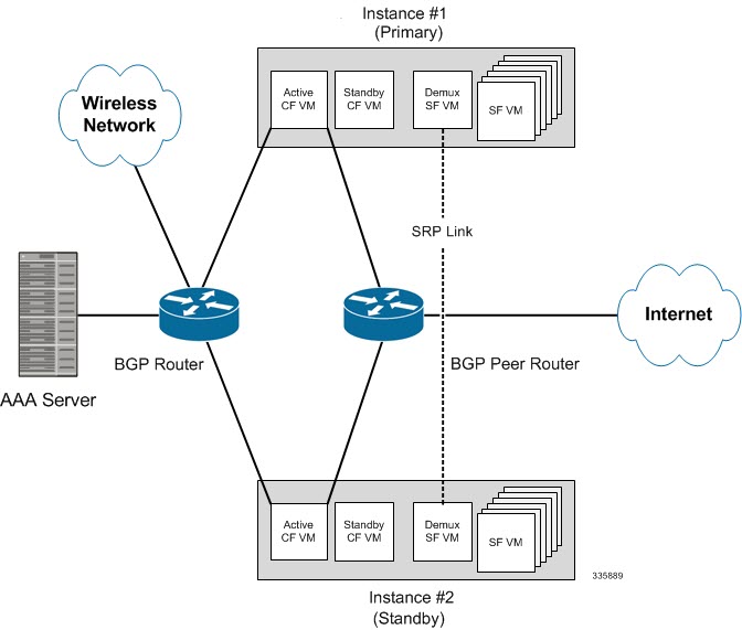
The system supports ICSR between two instances that support ICSR in the same StarOS release. For combination VMs where more than one service type is in use, only those services that support ICSR can make use of ICSR.

ICSR can provide redundancy for site/row/rack/host outages and major software faults. The two instances must be run on non-overlapping hosts and network interconnects. ICSR is only supported between identically configured VPC-DI or VPC-SI instances.

ASR 5500VPC-DIVPC-SI supports both L2 and L3 ICSR.

ICSR is implemented through the use of redundant virtual chassis. The virtual chassis for each ASR 5500VPC-DIVPC-SI instance are configured as primary and backup, with one being active and one standby. Both virtual chassis are connected to the same AAA server. A checkpoint duration timer controls when subscriber data is sent from the active chassis to the standby chassis. If the active chassis handling the call traffic goes out of service, the standby chassis transitions to the active state and continues processing the call traffic without interrupting the subscriber session.

The virtual chassis determine which is active through a proprietary TCP-based connection known as the Service Redundancy Protocol (SRP) link. The SRP link is used to exchange Hello messages between the active CFs in the primary and backup chassis and must be maintained for proper system operation. For additional information, refer to the Session Recovery chapter.

ICSR licenses are currently supported for the following services:

  • GGSN Gateway GPRS Support Node

  • P-GW Packet Data Network Gateway

  • S-GW Serving Gateway

  • SAE-GW System Architecture Evolution Gateway

L2TP Access Concentrator (LAC) functionality for ICSR is supported by the following protocol and services:

  • eGTP enhanced GPRS Tunneling Protocol

  • GGSN Gateway GPRS Support Node

  • P-GW Packet Data Network Gateway

  • SAEGW System Architecture Evolution Gateway

L2TP Access Concentrator (LAC) functionality for ICSR is not supported by the following service:

  • PMIP Proxy Mobile IP

L2TP Network Server (LNS) functionality for ICSR is not supported by any services.


Note

ICSR support for LAC requires a separate LAC license, as well as an Inter-Chassis Session Recovery license.


Note

Contact your Cisco account representative to verify whether a specific service supports ICSR as an option.


Interchassis Communication

Chassis configured to support ICSR communicate using periodic Hello messages. These messages are sent by each chassis to notify the peer of its current state. The Hello message contains information about the chassis such as its configuration and priority. A dead interval is used to set a time limit for a Hello message to be received from the chassis' peer. If the standby chassis does not receive an Hello message from the active chassis within the dead interval, the standby chassis transitions to the active state.

VPC-DI virtual chassis are configured to support ICSR communication using periodic Hello messages. These messages are sent by the active CF in each virtual chassis to notify the peer of its current state. The Hello message contains information about the virtual chassis such as its configuration and priority. A dead interval is used to set a time limit for a Hello message to be received from the chassis' CF peer. If the CF in the standby chassis does not receive a Hello message from the active CF in the active chassis within the dead interval, the standby virtual chassis transitions to the active state.

In situations where the SRP link goes out of service, a priority scheme is used to determine which chassis processes the session. The following priority scheme is used:

  • route modifier

  • chassis priority

  • MIO/UMIO/MIO2 MAC address

Checkpoint Messages

Checkpoint messages are sent from the active chassis to the standby chassis. These messages are sent at specific intervals and contain all the information needed to recreate the sessions on the standby chassis, if that chassis were to become active. Once a session exceeds the checkpoint duration, checkpoint data is collected on the session.

Checkpoint messages are sent from the active CF in the active virtual chassis to the active CF in the standby virtual chassis. These messages are sent at specific intervals and contain all the information needed to recreate the sessions on the standby chassis, if that chassis were to become active. Once a session exceeds the checkpoint duration, checkpoint data is collected on the session.

For additional information, refer to the ICSR Checkpointing appendix.

SRP CLI Commands

Exec Mode CLI Commands

Exec mode srp CLI configuration commands can be used to enable, disable and initiate SRP functions. The table below lists and briefly describes these commands. For complete information see the Exec Mode Commands (D-S) chapter of the Command Line Interface Reference.

Table 1. srp CLI Commands
Command Description
srp disable nack micro-chkpt-cmd Disables the sending of NACK messages from the standby chassis that may trigger a full checkpoint from the active chassis. Sending full checkpoints increases SRP bandwidth. This command disables the NACK feature for a specific micro-checkpoint which is failing continuously.
srp initiate-audit manual-with-sync Initiates a forced audit between ICSR chassis. This audit ensures that two ICSR peers are synchronized and identifies any discrepancies prior to scheduled or unscheduled switchover events.
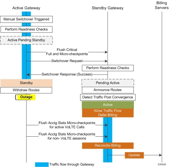
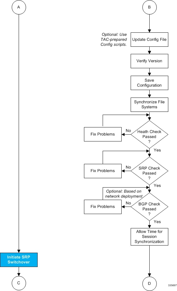
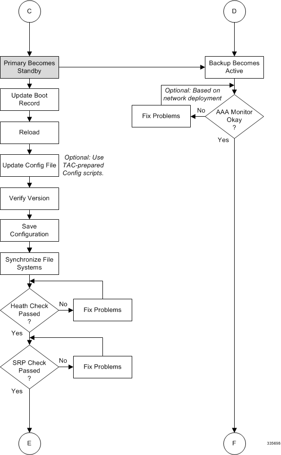
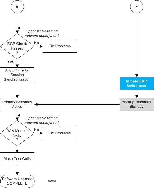
srp initiate-switchover Executes a forced switchover from active to inactive. When executed on the active chassis, this command switches the active chassis to the inactive state and the inactive chassis to an active state. See Note below.
srp reset-auth-probe-fail Resets the auth probe monitor failure information to 0.
srp reset-diameter-fail Resets the Diameter monitor failure information to 0.
srp terminate-post-process Forcibly terminates post-switchover processing.
srp validate-configuration Validates the configuration for an active chassis.
srp validate-switchover Validates that both active and standby chassis are ready for a planned SRP switchover.

Important

For release 20.0 and higher, ICSR will verify session manager connectivity on both chassis prior to allowing a manual switchover. If one or more of the session managers in the active chassis is not connected on the standby chassis, the switchover will not be initiated. An error message will appear on the screen noting the number of session managers that are mismatched. The force keyword can be used to initiate the switchover despite the mismatch(es). The output of the show checkpoint statistics verbose command will not indicate "Ready" for a session manager instance ("smgr inst") in the "peer conn" column for any instance that is not connected to the peer chassis.


show Commands

Exec mode show srp commands display a variety of information related to SRP functions. The table below lists and briefly describes these commands. For complete information on these commands, see the Exec Mode show Commands (Q-S) chapter of the Command Line Interface Reference.

Table 2. show srp Commands
Command Description
show srp audit-statistics Displays statistics of an external audit.
show srp call-loss statistics Displays the history of calls lost during switchover.
show srp checkpoint statistics Displays check pointing statistics on session redundancy data (session managers, current call recovery records, etc.).
show srp info Displays Service Redundancy Protocol information (context, chassis state, peer, connection state, etc.).
show srp monitor Displays SRP monitor information.
show srp statistics Displays SRP statistics (hello messages sent, configuration validation, resource messages, switchovers, etc.).

For additional information about the output of show srp commands, see the Statistics and Counters Reference.

AAA Monitor

AAA servers are monitored using the authentication probe mechanism. AAA servers are considered Up if the authentication-probe receives a valid response. AAA servers are considered Down when the max-retries count specified in the configuration of the AAA server has been reached. SRP initiates a switchover when none of the configured AAA servers responds to an authentication probe. AAA probing is only performed on the active chassis.


Important

A switchover event caused by an AAA monitoring failure is non-revertible.


If the newly active chassis fails to monitor the configured AAA servers, it remains as the active chassis until one of the following occurs:

  • a manual switchover

  • another non-AAA failure event causes the system to switchover

  • a CLI command is used to clear the AAA failure flag and allow the chassis to switch to standby

BGP Interaction

The Service Redundancy Protocol implements revertible switchover behavior via a mechanism that adjusts the route modifier value for the advertised loopback/IP Pool routes. The initial value of the route modifier value is determined by the chassis' configured role and is initialized to a value that is higher than a normal operational value. This ensures that in the event of an SRP link failure and an SRP task failure, the correct chassis is still preferred in the routing domain.


Important

For ICSR you must configure busyout ip pool commands in the same order on Active and Standby chassis to avoid SRP validation failures.


The Active and Standby chassis share current route modifier values. When BGP advertises the loopback and IP pool routes, it converts the route modifier into an autonomous systems (AS) path prepend count. The Active chassis always has a lower route modifier, and thus prepends less to the AS-path attribute. This causes the route to be preferred in the routing domain.

If communication on the SRP link is lost, and both chassis in the redundant pair are claiming to be Active, the previously Active chassis is still preferred since it is advertising a smaller AS-path into the BGP routing domain. The route modifier is incremented as switchover events occur. A threshold determines when the route modifier should be reset to its initial value to avoid rollover.

Requirements

ICSR configurations require the following:

  • Two VPC-DI instances or UGP instances identically configured for the same service types. The services must be bound on an SRP-activated loopback interface. Both instances must have identical hardware.

  • Two VPC-SI instances identically configured for the same service types. The services must be bound on an SRP-activated loopback interface. Both instances must have identical hardware.

  • Two chassis configured for the same service types. The services must be bound on an SRP-activated loopback interface.

  • Both chassis must have identical hardware.

  • Three contexts:

    • Redundancy – to configure the primary and backup chassis redundancy.

    • Source – AAA configuration of the specified nas-ip-address must be the IP address of an interface bound to an HA, or any core network service configured within the same context.

    • Destination – to configure monitoring and routing to the PDN.

  • Border Gateway Protocol (BGP) – ICSR uses the route modifier to determine the chassis priority.


Important

ICSR is a licensed Cisco feature. Verify that each chassis has the appropriate license before using these procedures. To do this, log in to both chassis and execute a show license information command. Look for "Inter-Chassis Session Recovery". If the chassis is not licensed, please contact your Cisco account representative.


RADIUS and Diameter protocols can be monitored to trigger a switchover.

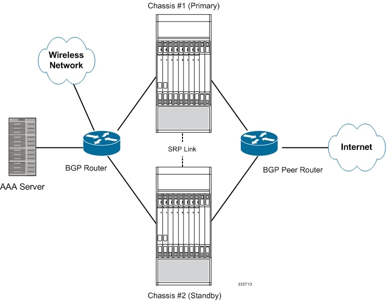
The following figure shows an ICSR network.

Figure 1. ASR 5500 ICSR Network
Figure 2. Virtualized StarOS ICSR Network

ICSR Operation

This section shows operational flows for ICSR.

The following figure shows an ICSR process flow due to a primary failure.

Figure 3. ICSR Process Flow (Primary Failure)

The following figure shows an ICSR process flow due to a manual switchover.

Figure 4. ICSR Process Flow (Manual Switchover)

Chassis Initialization

When the chassis are simultaneously initialized, they send Hello messages to their configured peer. The peer sends a response, establishes communication between the chassis, and messages are sent that contain configuration information.

During initialization, if both chassis are misconfigured in the same mode - both active (primary) or both standby (backup), the chassis with the highest priority (lowest number set with the ICSR priority command) becomes active and the other chassis becomes the standby.

If the chassis priorities are the same, the system compares the two MAC addresses and the chassis with the higher MIO/UMIO/MIO2 MAC address becomes active. For example, if the chassis have MAC addresses of 00-02-43-03-1C-2B and 00-02-43-03-01-3B, the last 3 sets of octets (the first 3 sets are the vendor code) are compared. In this example, the 03-1C-2B and 03-01-3B are compared from left to right. The first pair of octets in both MAC addresses are the same, so the next pairs are compared. Since the 01 is lower than the 1C, the chassis with the MIO/UMIO/MIO2 MAC address of 00-02-43-03-1C-2B becomes active and the other chassis the standby.

When StarOS is simultaneously initialized on each VPC-DI virtual chassis, the active CFs send Hello messages to each other. The peer sends a response, establishes communication between the chassis, and messages are sent that contain configuration information.

During initialization, if both virtual chassis are misconfigured in the same mode - both active (primary) or both standby (backup), the chassis with the highest priority (lowest number set with the ICSR priority command) becomes active and the other chassis becomes the standby.

If the chassis priorities are the same, StarOS compares the two MAC addresses of the active CFs and the chassis with the higher CF MAC address becomes active. For example, if the CFs have MAC addresses of 00-02-43-03-1C-2B and 00-02-43-03-01-3B, the last 3 sets of octets (the first 3 sets are the vendor code) are compared. In this example, the 03-1C-2B and 03-01-3B are compared from left to right. The first pair of octets in both MAC addresses are the same, so the next pairs are compared. Since the 01 is lower than the 1C, the VPC-DI virtual chassis with the CF MAC address of 00-02-43-03-1C-2B becomes active and the other chassis the standby.

When StarOS is simultaneously initialized on each VPC-SI virtual chassis, the chassis send Hello messages to their configured peer. The peer sends a response, establishes communication between the chassis, and messages are sent that contain configuration information.

During initialization, if both virtual chassis are misconfigured in the same mode - both active (primary) or both standby (backup), the chassis with the highest priority (lowest number set with the ICSR priority command) becomes active and the other chassis becomes the standby.

If the chassis priorities are the same, StarOS compares the two MAC addresses and the chassis with the higher MAC address becomes active. For example, if the VPC-SI instances have MAC addresses of 00-02-43-03-1C-2B and 00-02-43-03-01-3B, the last 3 sets of octets (the first 3 sets are the vendor code) are compared. In this example, the 03-1C-2B and 03-01-3B are compared from left to right. The first pair of octets in both MAC addresses are the same, so the next pairs are compared. Since the 01 is lower than the 1C, the VPC-SI virtual chassis with the MAC address of 00-02-43-03-1C-2B becomes active and the other chassis the standby.

Chassis Operation

This section describes how the chassis communicate, maintain subscriber sessions, and perform chassis switchover.

Chassis Communication

If one chassis is in the active state and one in the standby state, they both send Hello messages at each hello interval. Subscriber sessions that exceed the checkpoint session duration are included in checkpoint messages that are sent to the standby chassis. The checkpoint message contains subscriber session information so if the active chassis goes out of service, the backup chassis becomes active and is able to continue processing the subscriber sessions. Additional checkpoint messages occur at various intervals whenever subscriber session information is updated on the standby chassis.

The SRP Configuration mode checkpoint session command includes a number of keywords that enable you to:

  • Set the type of compression algorithm to be used for SRP payload messages.

  • Set the amount of time the chassis waits before check pointing an existing call session. Checkpoints can be separately set for IMS and/or non-IMS sessions.

  • Configure the interval between the sending of macro-checkpoints (full checkpoints) between the active and standby chassis.

For additional information see the Service Redundancy Protocol Configuration Mode Commands chapter in the Command Line Interface Reference.

If one virtual chassis is in the active state and one in the standby state, they both send Hello messages at each hello interval via their active CFs. Subscriber sessions that exceed the checkpoint session duration are included in checkpoint messages that are sent to the standby chassis. The checkpoint message contains subscriber session information so if the active chassis goes out of service, the backup chassis becomes active and is able to continue processing the subscriber sessions. Additional checkpoint messages occur at various intervals whenever subscriber session information is updated on the standby chassis.

The SRP Configuration mode checkpoint session command includes a number of keywords that enable you to:

  • Set the type of compression algorithm to be used for SRP payload messages.

  • Set the amount of time the chassis waits before check pointing an existing call session. Checkpoints can be separately set for IMS and/or non-IMS sessions.

  • Configure the interval between the sending of macro-checkpoints (full checkpoints) between the active and standby chassis.

For additional information see the Service Redundancy Protocol Configuration Mode Commands chapter in the Command Line Interface Reference.

Chassis Switchover

If the active chassis goes out of service, the standby chassis continues to send Hello messages. If the standby chassis does not receive a response to the Hello messages within the dead interval, the standby chassis initiates a switchover. During the switchover, the standby chassis begins advertising its srp-activated loopback and pool routes into the routing domain. Once the chassis becomes active, it continues to process existing AAA services and subscriber sessions that had checkpoint information, and is also able to establish new subscriber sessions.

When the primary chassis is back in service, it sends Hello messages to the configured peer. The peer sends a response, establishes communication between the chassis, and sends Hello messages that contain configuration information. The primary chassis receives an Hello message that shows the backup chassis state as active and then transitions to standby. The Hello messages continue to be sent to each peer, and checkpoint information is now sent from the active chassis to the standby chassis at regular intervals.

When chassis switchover occurs, the session timers are recovered. The access gateway session recovery is recreated with the full lifetime to avoid potential loss of the session and the possibility that a renewal update was lost in the transitional checkpoint update process.

If the active virtual chassis goes out of service, the standby chassis continues to send Hello messages. If the standby chassis does not receive a response to the Hello messages from the active CF within the dead interval, the standby chassis initiates a switchover. During the switchover, the active CF in the standby chassis begins advertising its srp-activated loopback and pool routes into the routing domain. Once the chassis becomes active, it continues to process existing AAA services and subscriber sessions that had checkpoint information, and is also able to establish new subscriber sessions.

When the primary virtual chassis is back in service, it sends Hello messages to the active CF in the configured peer. The peer sends a response, establishes communication between the active CFs in the chassis, and sends Hello messages that contain configuration information. The primary chassis receives an Hello message that shows the backup chassis state as active and then transitions to standby. The Hello messages continue to be sent to each peer, and checkpoint information is now sent from the active chassis to the standby chassis at regular intervals.

When chassis switchover occurs, the session timers are recovered. The access gateway session recovery is recreated with the full lifetime to avoid potential loss of the session and the possibility that a renewal update was lost in the transitional checkpoint update process.

Configuring ICSR


Important

The ICSR configuration must be the same on the primary and backup chassis. If each chassis has a different Service Redundancy Protocol (SRP) configuration, the session recovery feature does not function and sessions cannot be recovered when the active chassis goes out of service.


This section describes how to configure basic ICSR on each chassis. For information on commands that configure additional parameters and options, refer to the Command Line Interface Reference.


Important

For releases prior to StarOS 17.0, ICSR should not be configured for chassis supporting L2TP calls.


The procedures described below assume the following:

  • The chassis have been installed and configured with core network services.

    For more configuration information and instructions on configuring services, refer to the respective product Administration Guide.

  • In addition, the IP address pools must be srp activated.

  • AAA server is installed, configured and accessible by both chassis.

    For more information on configuring the AAA server, refer to the AAA Interface Administration and Reference.

  • BGP router installed and configured. See Routing for more information on configuring BGP services.

To configure ICSR on a primary and/or backup chassis:

Procedure


Step 1

Configure the SRP context by applying the example configuration in Configuring the Service Redundancy Protocol (SRP) Context.

Step 2

Modify the source context of the core network service by applying the example configuration in Modifying the Source Context for ICSR.

Step 3

Modify the destination context of core network service by applying the example configuration in Modifying the Destination Context for ICSR.

Step 4

Optional: Disable bulk statistics collection on the standby system by applying the example configuration in Disabling Bulk Statistics Collection on a Standby System.

Step 5

Verify your primary and backup chassis configuration as described in Verifying the Primary and Backup Configuration.

Step 6

Save your configuration as described in Verifying and Saving Your Configuration.


Configuring the Service Redundancy Protocol (SRP) Context

To configure the system to work with ICSR:

Procedure


Step 1

Create the chassis redundancy context and bind it to the IP address of the primary chassis by applying the example configuration in Creating and Binding the SRP Context. For VPC-DI instances, this should be the IP address of the active CF in the primary VPC-DI intance.

Step 2

Configure the chassis redundancy context with priority, chassis mode, hello interval, dead-interval and peer IP address by applying the example configuration in Configuring SRP Context Parameters.

Step 3

Configure the SRP context with interface parameters (including interface name, IP address and port number) for interchassis communication by applying the example configuration in Configuring the SRP Context Interface Parameters.

Step 4

Verify your SRP context configuration as described in Verifying SRP Configuration.

Step 5

Save your configuration as described in Verifying and Saving Your Configuration.


Creating and Binding the SRP Context

Use the example below to create the SRP context and bind it to primary chassis IP address:

Use the example below to create the SRP context and bind it to the IP address of the active CF in the primary VPC-DI instance:


Important

ICSR is configured on two chassis. Be sure to create the redundancy context on both systems. CLI commands must be executed on both systems. Log onto both chassis before continuing. Always make configuration changes on the primary chassis first. Before starting this configuration, identify which chassis to configure as the primary and use that login session.


Important

ICSR is configured on two VPC-DI instances. Be sure to create the redundancy context on both systems. CLI commands must be executed on both systems. Log onto both active CFs before continuing. Always make configuration changes on the active CF in the primary VPC-DI instance first. Before starting this configuration, identify which VPC-DI to configure as the primary and use that login session.


configure 
  context srp_ctxt_name [-noconfirm] 
    service-redundancy-protocol 
      bind address ip_address 
      end 

Notes:

  • ICSR should be configured and maintained in a separate context.

  • Be sure to bind the local IP address to the primary chassis. When configuring the backup chassis, be sure to bind the local IP address to the backup chassis.

  • Be sure to bind the local IP address to the active CF in the primary VPC-DI instance. When configuring the backup VPC-DI instance, be sure to bind the local IP address to the backup chassis.

Configuring SRP Context Parameters


Important

CLI commands must be executed on both chassis. Log onto both chassis before continuing. Always make configuration changes on the primary chassis first.

CLI commands must be executed on both VPC instances. Log onto both active CFs before continuing. Always make configuration changes on the primary VPC instance first.


Basic Parameters

This configuration assigns a chassis mode and priority, and also configures the redundancy link between the primary and backup chassis:

configure 
  context srp_ctxt_name 
    service-redundancy-protocol 
      chassis-mode { primary | backup } 
      priority priority 
      peer-ip-address ip_address 
      hello-interval dur_sec 
      dead-interval dead_dur_sec 
      end 

Notes:

  • ICSR should be configured and maintained in a separate context.

  • When assigning the chassis mode on the backup chassis be sure to enter the backup keyword.

  • The checkpoint command sets the amount of time the chassis waits before check pointing an existing call session. Checkpoints can be set for IMS (VoLTE) and/or non-IMS sessions. The checkpoint is a snapshot of the current application state that can be used to restart its execution in case of failure. The default setting is 60 seconds.

  • The priority determines which chassis becomes active in the event that both chassis are misconfigured with the same chassis mode; see Chassis Initialization. The higher priority chassis has the lower number. Be sure to assign different priorities to each chassis.

  • Enter the IP chassis of the backup chassis as the peer-ip-address to the primary chassis. Assign the IP address of the primary chassis as the peer-ip-address to the backup chassis.

  • The dead-interval must be at least three times greater than the hello-interval. For example, if the hello interval is 10, the dead interval should be at least 30. System performance is severely impacted if the hello interval and dead interval are not set properly. An optional delay-interval command allows you to delay the start dead-interval for an interval following the loading of configuration files.

SRP Redundancy, AAA and Diameter Guard Timers

Guard timers ensure that local failures, such as reboots and task restarts, do not result in ICSR events which can be disruptive.

The guard timer command configures the redundancy-guard-period and monitor-damping-period for SRP service monitoring.

configure 
  context context_name 
    service-redundancy-protocol variable 
      guard-timer { aaa-switchover-timers { damping-period seconds | guard-period seconds } | diameter-switchover-timers { damping-period seconds | guard-period seconds } | srp-redundancy-timers { aaa  { damping-period seconds | guard-period seconds } | bgp { damping-period seconds | guard-period seconds } | diam  { damping-period seconds | guard-period seconds } } 
      end 

Notes:

  • aaa-switchover-timers – sets timers that prevent back-to-back ICSR switchovers due to an AAA failure (post ICSR switchover) while the network is still converging.

    • damping-period – configures a delay time to trigger an ICSR switchover due to a monitoring failure within the guard-period.

    • guard-period – configures the local-failure-recovery network-convergence timer.

  • diameter-switchover-timers – sets timers that prevent a back-to-back ICSR switchover due to a Diameter failure (post ICSR switchover) while the network is still converging.

    • damping-period – configures a delay time to trigger an ICSR switchover due to a monitoring failure within the guard-period.

    • guard-period – configures the local-failure-recovery network-convergence timer.

  • srp-redundancy-timers – sets timers that prevent an ICSR switchover while the system is recovering from a local card-reboot/critical-task-restart failure.
    • aaa – local failure followed by AAA monitoring failure

    • bgp – local failure followed by BGP monitoring failure

    • diam – local failure followed by Diameter monitoring failure

DSCP Marking of SRP Messages

You can enable separate DSCP marking of SRP control and checkpoint messages. The dscp-marking command sets DSCP marking values for SRP control and checkpoint (session maintenance) messages.

configure 
  context context_name 
    service-redundancy-protocol 
      dscp-marking { control | session } dscp_value 

Notes:

  • dscp_value can be:
    • af11 – Assured Forwarding Class 1 low drop PHB (Per Hop Behavior)
    • af12 – Assured Forwarding Class 1 medium drop PHB
    • af13 – Assured Forwarding Class 1 high drop PHB
    • af21 – Assured Forwarding Class 2 low drop PHB
    • af22 – Assured Forwarding Class 2 medium drop PHB
    • af23 – Assured Forwarding Class 2 high drop PHB
    • af31 – Assured Forwarding Class 3 low drop PHB
    • af32 – Assured Forwarding Class 3 medium drop PHB
    • af33 – Assured Forwarding Class 3 high drop PHB
    • af41 – Assured Forwarding Class 4 low drop PHB
    • af42 – Assured Forwarding Class 4 medium drop PHB
    • af43 – Assured Forwarding Class 4 high drop PHB
    • be – Best effort Per-Hop-Behaviour (default)
    • cs1 – Class selector 1 PHB
    • cs2 – Class selector 2 PHB
    • cs3 – Class selector 3 PHB
    • cs4 – Class selector 4 PHB
    • cs5 – Class selector 5 PHB
    • cs6 – Class selector 6 PHB
    • cs7 – Class selector 7 PHB
    • ef – Expedited Forwarding PHB, for low latency traffic

Optimizing Switchover Transitions

There are several SRP configuration options that reduce the transition time from the active to standby gateways (primarily P-GW) in support of VoLTE traffic.


Important

These features require an updated ICSR license to support the enhancements. Contact your Cisco account representative for additional information.


Allow Non-VoLTE Traffic During ICSR Switchover

The ICSR framework reduces switchover disruption for VoLTE traffic by enabling VoLTE traffic on the newly active gateway prior to reconciling the billing information and enabling communication with the newly active gateway when accounting is not deemed critical.

This functionality extends to all other traffic, including data sessions and default bearer traffic for IMS/e911, The following ICSR functionality is provided for all non-VoLTE data traffic:
  • When a switchover occurs, the newly active gateway forwards all traffic the moment the gateway becomes active.
  • External communication with billing servers is deferred. See the traffic flow diagram below.
  • When the newly active gateway receives all billing-related checkpointing information from the previously active gateway, it reconciles the billing data before communicating with external billing servers OCS (Online Charging System) or OFCS (Offline Charging System).
Figure 5. Call Flow: Reduce Non-VoLTE Data Outage

The switchover allow-all-data-traffic SRP Configuration mode CLI command allows all data traffic (VoLTE and non-VoLTE) during switchover transition. This command overwrites the switchover allow-volte-data-traffic command if enabled on a P-GW.

configure 
  context context_name 
    service-redundancy-protocol 
      switchover allow-all-data-traffic 

Important

The switchover allow-all-data-traffic command must be run on both chassis to enable this feature.


The switchover allow-volte-data-traffic SRP Configuration mode CLI command allows VoLTE data traffic during ICSR switchover transition.

configure 
  context context_name 
    service-redundancy-protocol 
      switchover allow-volte-data-traffic [ maintain-accounting ] 

Notes:

  • When maintain-accounting is enabled, accounting accuracy is maintained for VoLTE calls.VoLTE data is allowed on the active gateway after VoLTE accounting statistics are flushed.
Allow All Data Traffic

The SRP Configuration mode switchover allow-all-data-traffic command allows all data traffic (VoLTE and non-VoLTE) during switchover transition. This command overwrites the switchover allow-volte-data-traffic command if enabled on a P-GW. This feature reduces data traffic outage during the switchover.


Important

This CLI command must be run on both the active and standby chassis to enable this feature.


All data traffic is allowed on the active chassis during flushing and internal auditing. The billing information is reconciled in the background once the flush is complete.

Allow Early Active Transition

The SRP Configuration mode switchover allow-early-active-transition command enables early transition to active state during an ICSR switchover. By default this feature is disabled.

Use this command in concert with the switchover allow-all-data-traffic or allow-volte-data-traffic (without maintain accounting option) command to further reduce data outage during a planned switchover. The outage window is the amount time between initiating an ICSR switchover and when the newly active chassis starts processing data.


Important

You must enable one of the commands identified above on both ICSR chassis prior to enabling this command.


Graceful Cleanup of ICSR After Audit of Failed Calls

During an Audit on the gateways (P-GW/S-GW/GGSN/SAE-GW) after Session Recovery or an ICSR event, if any critical information, internally or externally related to a subscriber session seems inconsistent, ICSR will locally purge the associated session information.

Since external gateways (peer nodes) are unaware of the purging of this session, the UE session may be maintained at other nodes. This leads to hogging of resources external to the gateway and an unreachable UE for VoLTE calls.

When this feature is enabled, graceful cleanup for an ICSR audit of failed calls occurs. External signaling notifies peers of session termination before purging the session. The gateway will attempt to notify external peers of the removal of the session. External nodes to the local gateway include S-GW, P-GW, SGSN, MME, AAA, PCRF and IMSA.

Audit failure can occur because of missing or incomplete session information. Therefore, only the peers for which the information is available will be notified.

The require graceful-cleanup-during-audit-failure Global Configuration mode CLI command enables or disables the graceful cleanup feature.
configure 
  require graceful-cleanup-during-audit-failure [ del-cause non-ims-apn   { system-failure | none } ] 
Optimization of Switchover Control Outage Time

The ICSR framework minimizes control outage time associated with the flushing of critical full checkpoint statistics, network convergence and internal auditing.

The amount of time consumed by the following activities affects control outage time during switchover:

  • Critical Flush – During the Active to Pending-Standby transition, all sessmgrs flush any pending critical FCs (Full Checkpoints). During this time, the active chassis drops all control packets. If control signaling is allowed during this stage, a call may get disconnected based on the control message type and accounting information will be lost.
  • Network Convergence – This encompasses the amount of time taken to update routes and send control/data to the newly active chassis. Control messages are dropped during the transition.
  • Accounting Flush – During this flush stage data counts are synchronized between chassis. If control signaling is allowed during this flush, the call may get disconnected based on the control message type, and accounting information will be lost for calls that existed before switchover.
  • Audit – During audit new calls are not allowed because synchronization of call resources may result in clearing of the calls.

The switchover control-outage-optimization CLI command allows new calls during the Accounting Flush, as soon as the Audit is completed. This SRP Configuration mode command enables the quicker restoration of control traffic (call-setup, modification, deletion) following an ICSR switchover.

configure 
  context context_name 
    service-redundancy-protocol 
      switchover control-outage-optimization 
      end 

Configuring the SRP Context Interface Parameters

This procedure configures the communication interface with the IP address and port number within the SRP context. This interface supports interchassis communication.


Important

CLI commands must be executed on both chassis. Log onto both chassis before continuing. Always make configuration changes on the primary chassis first.


configure 
  context vpn_ctxt_name [-noconfirm] 
      interface srp_if_name 
      ip-address { ip_address | ip_address/mask } 
      exit 
    exit 
  port ethernet slot_num/port_num 
    description des_string 
    medium { auto | speed { 10 | 100 | 1000 } duplex { full | half } } 
    no shutdown 
    bind interface srp_if_name srp_ctxt_name  
    end 

Configuring NACK Generation for SRP Checkpoint Messaging Failures

Enabling NACK Messaging from the Standby Chassis

Transport (TCP) level re-transmission is supported on the SRP link between ICSR chassis. SRP configuration also supports optional application level checks to ensure checkpoints are received at the Standby chassis. Failed attempts to receive and apply checkpoints send NACK messages to the Active chassis.

When this feature is enabled and the standby chassis sends a NACK in response to the receipt of a micro-checkpoint (MC) that fails to be successfully applied, the standby chassis sends another NACK. The standby chassis will send more NACKs (configurable, default = 3) within a 10-minute window if a macro-checkpoint (FC) is not received. NACKs will continue to be sent and the 10-minute reset until an FC is received and applied, or the configured number of max-responses is reached.

You can also specify the number of times a NACK is sent within the 10-minute window in response to a failed MC or FC (Default = 3).

A nack keyword in the SRP Configuration mode checkpoint session command allows you to enable generation of NACK messages in response to checkpoint message failures on a Standby ICSR chassis.


Important

The nack keyword will only appear if a special ICSR optimization feature license has been purchased and installed. Contact your Cisco account representative for assistance.


configure 
   context context_name 
      service-redundancy-protocol variable 
         checkpoint session nack { macro | micro } [ max-response number ]  
         no checkpoint session nack { macro | micro }  
         end 

Notes:

  • max-response is the number of times a NACK is sent within the 10-minute window in response to a failed MC or FC expressed as an integer from 0 through 65535 (Default = 3).

A periodic-interval keyword in the SRP Configuration mode checkpoint session command allows you to configure the interval between the sending of macro-checkpoints (FCs) between the active and standby chassis.


Important

The periodic-interval keyword will only appear if a special ICSR optimization feature license has been purchased and installed. Contact your Cisco account representative for assistance.


configure 
   context context_name 
      service-redundancy-protocol variable 
         checkpoint session periodic-interval minutes  
         default checkpoint session periodic-interval  
         no checkpoint session periodic-interval  
         end 
Selective Disabling of NACK Messaging

The NACK mechanism sends a NACK message for any ICSR checkpoint failure on the standby chassis. Every NACK sent from the standby chassis triggers a full checkpoint from the active chassis.

If the micro-checkpoint is failing continuously and sending NACKs, the active chassis keeps sending full-checkpoints. This increases SRP bandwidth.

CLI commands allow an operator to selectively disable and re-enable NACK messages for specific micro-checkpoints.

The Exec mode srp disable nack micro-chkpt-cmd disables the sending of a NACK from the standby chassis.

srp disable nack micro-chkpt-cmd  chkpt_number 

chkpt_number specifies the checkpoint number to be disabled as an integer from 1 through 255. You can obtain checkpoint numbers (CMD IDs) from the output of the show srp checkpoint info command.

You can re-enable the micro-checkpoint using the srp enable nack micro-chkpt-cmd command.

srp enable nack micro-chkpt-cmd  chkpt_number 

Configuring LZ4 Compression Algorithm

You can optionally enable LZ4 compression algorithm for SRP messaging payload. The zlib algorithm remains as the default.

LZ4 is a very fast lossless compression algorithm with near-linear scalability for multi-threaded applications.

The compression keyword in the SRP Configuration mode checkpoint session command allows you to enable the use of the LZ4 compression algorithm.


Important

The compression keyword will only appear if a special ICSR optimization feature license has been purchased and installed. Contact your Cisco account representative for assistance.


The following command sequence enables the use of LZ4 compression:

configure 
   context context_name 
      service-redundancy-protocol  
         checkpoint session compression lz4 
         end 

LZ4 compression is effective only if both chassis are configured with LZ4. If any one chassis has zlib (default) configured, the compression algorithm reverts to zlib. The algorithm is negotiated only during initial socket establishment. Once agreed no more negotiation takes place until the TCP socket connection is reset.

Reducing Sync-Up Time with Standby ICSR Chassis

The default method for synchronizing the SRP database requires tens of seconds of delay whenever the TCP connection between the Active and Standby session managers is established. Once the TCP connection is established, heart beat messages are exchanged between both ICSR chassis every 3 seconds. The standby chassis waits for seven heart beat messages from the active chassis before it is ready to accept data. This may cause significant delay in session manager database synchronization on the standby chassis.

You can enable an aggressive method for synchronizing the session manager database reduces recovery time in the following scenarios:

  • Standby Session Manager crash
  • Packet processing card failure on Standby chassis
  • Standby chassis reboot
  • Temporary loss and recovery of SRP connection

The aggressive method reduces the number of heartbeat messages and amount of housekeeping information exchanged between ICSR chassis.

The SRP Configuration mode standby database-recovery aggressive command allows you to select normal or aggressive restoration of the SRP database.

The following command sequence enables the aggressive recovery mode:

configure 
   context context_name 
      service-redundancy-protocol  
         standby database-recovery aggressive 
         end 

The default form of this command restores the normal mode of SRP database recovery.

Verifying SRP Configuration

Verify that your SRP contexts were created and configured properly by running the show srp info command (Exec Mode) on each chassis.

Notes:

  • The interval is specified as an integer divisible by 15 in the range from 30 through 1440 (Default = 45 minutes). The interval range for sending full checkpoints is 30 minutes to 24 hours (1140 minutes).

Modifying the Source Context for ICSR

To modify the source context of core service:

Procedure


Step 1

Add the Border Gateway Protocol (BGP) router AS-path and configure the gateway IP address, neighbor IP address, remote IP address in the source context where the core network service is configured, by applying the example configuration in Configuring BGP Router and Gateway Address.

Step 2

Configure the service redundancy context with the BGP neighbor context and IP address to monitor the BGP link activity by applying the example configuration in Configuring the SRP Context for BGP.

Step 3

Verify your BGP context configuration by following the steps in Verifying BGP Configuration.

Step 4

Save your configuration as described in Verifying and Saving Your Configuration.


Configuring BGP Router and Gateway Address

Use the following example to create the BGP context and network addresses.

configure 
  context source_ctxt_name 
    router bgp AS_num 
      network gw_ip_address 
      neighbor neighbor_ip_address remote-as AS_num 
      end 

Notes:

  • source_ctxt_name is the context where the core network service is configured.

Configuring the SRP Context for BGP

Use the following example to configure the BGP context and IP addresses in the SRP context.

configure 
  context srp_ctxt_name 
    service-redundancy-protocol 
      monitor bgp context source_ctxt_name neighbor_ip_address 
      end 

neighbor_ip_address can be entered in IPv4 dotted-decimal or IPv6 colon-separated-hexadecimal notation. Multiple IP addresses can be added per context as IPv4 and/or IPv6 IP addresses.

An ICSR failover is triggered when all BGP peers within a context are down.

Optionally, you can configure SRP peer groups within a context. ICSR failover would then occur if all peers within a group fail. This option is useful in deployments in which a combination of IPv4 and IPv6 peers are spread across multiple paired VLANs, and IPv4 or IPv6 connectivity is lost by all members of a peer group.

A sample configuration for SRP peer groups within a context ("PGWin") appears below.

monitor bgp context PGWin 10.1.1.16 group 1 
monitor bgp context PGWin 10.1.1.17 group 1 
monitor bgp context PGWin 69.2.215.0 group 2 
monitor bgp context PGWin 69.2.215.1 group 2 
monitor bgp context PGWin 2001:4333:201:1102:103:2a1:: group 3 
monitor bgp context PGWin 2001:4333:201:1102:103:2a1:0:1 group 3 

In the above sample configuration, ICSR failover would occur if both addresses in group 1, 2 or 3 lost connectivity.

For additional information refer to the description of the monitor bgp, monitor diameter and monitor authentication-probe commands in the Service Redundancy Protocol Configuration Mode Commands chapter of the Command Line Interface Reference.

Verifying BGP Configuration

Verify your BGP configuration by entering the show srp monitor bgp command (Exec Mode).

Modifying the Destination Context for ICSR

To modify the destination context of core service:

Procedure


Step 1

Add the BGP router and configure the gateway IP address, neighbor IP address, remote IP address in the destination context where the core network service is configured, by applying the example configuration in Configuring BGP Router and Gateway Address in Destination Context.

Step 2

Configure the service redundancy context with BGP neighbor context and IP address to monitor the BGP link activity by applying the example configuration in Configuring SRP Context for BGP for Destination Context.

Step 3

Set the subscriber mode to default by following the steps in Setting Subscriber to Default Mode.

Step 4

Verify your BGP context configuration by following the steps in Verifying BGP Configuration in Destination Context.

Step 5

Save your configuration as described in Verifying and Saving Your Configuration.


Configuring BGP Router and Gateway Address in Destination Context

Use the following example to create the BGP context and network addresses.

configure 
  context dest_ctxt_name 
    router bgp AS_num 
      network gw_ip_address 
      neighbor neighbor_ip_address remote-as AS_num 
      end 

Notes:

  • AS_num is the autonomous systems path number for this BGP router.

Configuring SRP Context for BGP for Destination Context

Use the following example to configure the BGP context and IP addresses in the SRP context.

configure 
  context srp_ctxt_name 
    service-redundancy-protocol 
      monitor bgp context dest_ctxt_name neighbor_ip_address 
      end 

Setting Subscriber to Default Mode

Use the following example to set the subscriber mode to default.

configure 
  context dest_ctxt_name 
    subscriber default 
      end 

Verifying BGP Configuration in Destination Context

Verify your BGP configuration by entering the show srp monitor bgp command (Exec Mode).

Disabling Bulk Statistics Collection on a Standby System

You can disable the collection of bulk statistics from a system when it is in the standby mode of operation.


Important

When this feature is enabled and a system transitions to standby state, any pending accumulated statistical data is transferred at the first opportunity. After that no additional statistics gathering takes place until the system comes out of standby state.


Use the following example to disable the bulk statistics collection on a standby system.

configure 
  bulkstat mode 
    no gather-on-standby 
    end 

Repeat this procedure for both systems.

Verifying the Primary and Backup Configuration

This section describes how to compare the ICSR configuration on the primary and backup systems.

Procedure


Step 1

Enter the show configuration srp command on each system (Exec mode).

Step 2

Verify that both chassis have the same SRP configuration information.

The output looks similar to following:
config 
  context source 
    interface haservice loopback 
      ip address 172.17.1.1 255.255.255.255 srp-activate 
    #exit 
    radius attribute nas-ip-address address 172.17.1.1 
    radius server 192.168.83.2 encrypted key 01abd002c82b4a2c port 1812 
    radius accounting server 192.168.83.2 encrypted key 01abd002c82b4a2c port 1813 
    ha-service ha-pdsn 
      mn-ha-spi spi-number 256  encrypted secret 6c93f7960b726b6f6c93f7960b726b6f hash-algorithm md5 
      fa-ha-spi remote-address 192.168.82.0/24 spi-number 256 encrypted secret 1088bdd6817f64df 
      bind address 172.17.1.1 
    #exit 
  #exit 
  context destination 
    ip pool dynamic 172.18.0.0 255.255.0.0 public 0 srp-activate 
    ip pool static 172.19.0.0 255.255.240.0 static srp-activate 
  #exit 
  context srp 
    service-redundancy-protocol 
    #exit 
  #exit 

Configuring Subscriber State Management Audit Process

This audit is to ensures that two ICSR peers are in synch and identifies any discrepancies prior to any scheduled or unscheduled switchover events.

Procedure


Step 1

Enter the SRP Context mode and enter the service-redundancy-protocol command.

Step 2

Enter the audit daily-start-time command. Specify the daily start time as an hour and minute. For example, a start time of 06 00 indicates that the audit will begin at 6:00 AM.

Step 3

Enter the audit periodicity command. Specify the interval in minutes for generating SRP audit statistics as an integer from 60 through 1440. For example, a periodicity of 90 indicates that SRP audit statistics will be generated every 90 minutes beginning at the specified start time. Default = 60.

A sample configuration sequence appears below.
config 
  context srp 
    service-redundancy-protocol 
      audit daily-start-time 06 00 
      audit periodicity 90 
      end 

Troubleshooting ICSR Operation

SSD

StarOS supports an ICSR-specific show support details (SSD) command that outputs the results from a series of Exec mode show commands.This mini SSD reduces capture time when debugging ICSR timing issues between the Active and Standby chassis, facilitating quicker resolution of the problem.

The show support details icsr command produces a mini SSD that contains the output of the following show commands:
  • show srp info
  • show srp checkpoint statistics
  • show srp checkpoint statistics verbose
  • show srp checkpoint statistics debug-info
  • show srp checkpoint statistics sessmgr all
  • show srp checkpoint statistics sessmgr all debug-info
  • show srp checkpoint statistics ipsecmgr all
  • show srp checkpoint statistics sessmgr all write-list-stats
  • show srp checkpoint info
  • show srp monitor
  • show srp monitor all
  • show srp monitor diameter debug
  • show srp statistics
  • show srp call-loss statistics
  • show srp audit-statistics
  • show session subsystem facility sessmgr all debug-info

The SSD output can be directed to a file that can be stored to /flash or off the chassis. For additional information, see the Command Line Interface Reference.

show srp details

The Exec mode show srp details command displays comprehensive information used by TAC personnel to troubleshoot ICSR/SRP issues.

Updating the Operating System

Updating the operating system (StarOS™) on an ICSR system is performed separately on each system while it is in standby mode. Traffic disruption is minimal since an active system will be handling call sessions while the standby system is being updated.

The general upgrade sequence is as follows:

  1. Download the StarOS software image and copy/transfer it to both the active and standby system.

  2. Save the currently running configurations on both systems.

  3. Update the standby backup system first.

  4. Initiate an SRP switchover from the active primary system to make the standby backup system active.

  5. Update the standby primary system.

  6. Initiate an SRP switchover from the active backup system to make the standby primary system active.

The four-part flowchart below shows a more complete view of all the procedures required to complete the StarOS upgrade process.

Figure 6. ICSR Software Upgrade – Part 1
Figure 7. ICSR Software Upgrade – Part 2
Figure 8. ICSR Software Upgrade – Part 3
Figure 9. ICSR Software Upgrade – Part 4

Both ICSR Systems

Perform the tasks described below on both the primary (active) and backup (standby) ICSR systems.

Downloading and Transferring the StarOS Image

Procedure

Step 1

Verify that there is enough free space on the /flash device to accommodate the new operating system image file by entering the following Exec mode command:[local]host_name# directory /flash

Step 2

Access to the Cisco support site and download facility is username and password controlled. Download the software image to a network location or physical device (USB stick) from which it can be uploaded to the /flash device.

Step 3

Transfer the new operating system image file to the /flash device on the MIO/UMIO/MIO2 using one of the following methods:

  1. Copy the file from a network location or local device plugged into the MIO/UMIO/MIO2 using the copy command.

    [local]host_name# copy from_url to_url [-noconfirm] 
  2. Transfer the file to the /flash device using an FTP client with access to the system. The FTP client must be configured to transfer the file using binary mode.

  3. Transfer the file to the /flash device using an SFTP client with access to the system.

In release 20.0 and higher Trusted StarOS builds, FTP is not supported.
Step 4

Verify that the image file was successfully transferred to the /flash device by running the Exec mode the following command:

[local]host_name# directory /flash 
Step 5

Run the show version /flash/image_filename command to verify the build information.

Any CRC errors will be displayed in the output of this command. If any errors appear, check the build and re-transfer it onto the chassis. Confirm that the correct image version and build description is displayed

Downloading and Transferring the StarOS Image

Procedure

Step 1

Verify that there is enough free space on the /flash device to accommodate the new operating system image file by entering the following Exec mode command:

[local]host_name directory /flash 
Step 2

Access to the Cisco support site and download facility is username and password controlled. Download the software image to a network location or local drive from which it can be uploaded to the /flash device.

Step 3

Transfer the new operating system image file to the /flash device using one of the following methods:

  1. Copy the file from a network location or local drive using the copy command

    [local]host_name copy from_url to_url [-noconfirm] 
  2. Transfer the file to the /flash device using an FTP client with access to the system. The FTP client must be configured to transfer the file using binary mode.

  3. Transfer the file to the /flash device using an SFTP client with access to the system.

Step 4

Verify that the image file was successfully transferred to the /flash device by running the following Exec mode command:

[local]host_name directory /flash 
Step 5

Run the show version /flash/image_filename command to verify the build information. For example:

local]host_name show version /flash/image_filename.bin 
Note 

Any CRC errors will be displayed in the output of the above command. If any errors appear, check the build and re-transfer it onto the chassis. Confirm that the correct image version and build description is displayed


Standby ICSR System

Perform the tasks described below on the backup or standby ICSR system.

Performing Health Checks

Health checks are a series of Exec mode show commands to determine the readiness of the system to handle a software update.

Procedure

Step 1

Run show card table all |grep unknown. No output should be displayed.

Step 2

Run show card table |grep offline. No output should be displayed.

Step 3

Run show resources |grep Status. The output should display "Within acceptable limits ".

Step 4

Run show alarm outstanding. Review the output for any issues that may preclude performing the software update.


Performing SRP Checks

Service Redundancy Protocol (SRP) checks verify that the mechanism for monitoring ICSR system status is operational.

Procedure

Step 1

Run show srp monitor all.

Step 2

Review the output for any issues that may preclude performing the software update.


Performing BGP Checks

Border Gateway Protocol (BGP) checks are only required when BGP is used to support redundant interchassis communication. These checks are run per context and per service type.

Procedure

Step 1

For each BGP-enabled context, run show ip bgp summary. Verify that the BGP peers are connected and that IPv4 and IPv6 peers are up. Repeat for all BGP-enable contexts.

Step 2

Run show service_name all |grep "Service Status:". The service should be "Started". Repeat for all services running on the chassis.


Updating the Boot Record

You must add a new boot stack entry for the recently downloaded software image (.bin) file.

Procedure

Step 1

Run the Exec mode show boot command to verify that there are less than 10 entries in the boot.sys file and that a higher priority entry is available (minimally there is no priority 1 entry in the boot stack).

Step 2

Create a new boot stack entry for the new file group, consisting of the new operating system image file and the currently used CLI configuration file by entering the following Global Configuration command:

[local]host_name(config)# boot system priority number image image_url /flash/filename config cfg_url /flash/filename 
Step 3

Assign the next highest priority to this entry, by using the <N-1> method, wherein you assign a priority number that is one number less than your current highest priority.

If priority 1 is in use, you must renumber the existing entries to ensure that at least that priority is available.
The maximum number of boot stack entries that can be contained in the boot.sys file is 10. If there are already 10 entries in the boot stack, you must delete at least one of these entries (typically, the lowest priority) and, if necessary, renumber some or all of the other entries before proceeding. Use the no boot system priority command to delete a book stack entry.
For information on using the boot system priority command, refer to the Adding a New Boot Stack Entry section in this guide

Synchronizing File Systems

Synchronize the local file systems by entering the following Exec mode command:

[local]host_name# filesystem synchronize all  

Reboot StarOS

Reboot the StarOS by entering the following command:

[local]host_name# reload [-noconfirm] 

As the system reboots, it loads the new operating system software image and its corresponding CLI configuration file using the new boot stack entry configured earlier.

After the system reboots, establish a CLI session and enter the show version command to verify that the active software version is correct.

Optional for PDSN: If you are using the IP Pool Sharing Protocol during your upgrade, refer to Configuring IPSP Before the Software Upgrade in the PDSN Administration Guide.

Updating the Configuration File

Features in the new operating system may require changes to the configuration file. These changes can be done manually or facilitated by custom scripts prepared by Cisco TAC. Make whatever changes are necessary prior to saving the updated configuration file.

Verifying the Software Version

After the system has successfully booted, verify that the new StarOS version is running by executing the Exec mode show version command.

You can run the Exec mode show build command to display additional information about the StarOS build release.

Saving the Configuration File

Use the Exec mode save configuration command to save the currently running configuration to the /flash device and to an off-chassis location (external memory device or network URL). The off-chassis copy assures that you will have a fallback, loadable configuration file should a problem be encountered.

Waiting for Session Synchronization

Allow time for session synchronization to occur between the ICSR chassis before preceding to the next steps.

Procedure

Step 1

Run the show session recovery status verbose command on both chassis. Proceed to the next steps only when no errors are seen in the output of this command.

Step 2

On the standby chassis, run show srp checkpoint statistics |more.

Step 3

On active chassis, run show subs summary |grep Total.

Step 4

Compare the number of subscribers on the active chassis and the number of Current pre-allocated calls: on the standby chassis. They should be similar (within 5%). Allow a few minutes for systems to complete synchronization.


Primary System

Perform the tasks described below on the primary (active) ICSR system.

Initiating an SRP Switchover

An SRP switchover places the primary chassis in standby mode and makes the backup chassis active. The secondary chassis is now processing sessions with the upgraded software.

Procedure

Step 1

On the primary chassis run the srp initiate-switchover command. All existing sessions will be migrated to the backup chassis and it begins servicing new session requests. Allow the switchover process to complete.

Step 2

On the primary chassis, run the show srp info command. Chassis State should indicate Standby when switchover is complete.

Step 3

On the backup chassis, confirm the switchover is complete by running the show srp info command. Chassis State should indicate Active when switchover is complete.


Checking AAA Monitor Status on the Newly Active System

If your network deployment requires communication with AAA servers, log into the newly active system and perform an AAA monitor check. You will be checking for the existence of any SNMP traps that indicate the system cannot communicate with AAA servers (starSRPAAAUnreachable).

Procedure

Step 1

Run the Exec mode command show snmp trap history |grep starSRPAAAUnreachable.

Step 2

There should be no output for this command, or no very recent SNMP trap notifications (based on the event timestamp).

Step 3

If the active system cannot communicate with one or more AAA servers, refer to AAA Monitor for additional information.


Initiating an SRP Switchover

This SRP switchover places the primary system in active mode and returns the backup system to the standby. The primary chassis is now processing sessions with the upgraded software.

Procedure

Step 1

On the backup chassis run the srp initiate-switchover command. All existing sessions will be migrated to the primary chassis which begins servicing new session requests. Allow the switchover process to complete.

Step 2

On the backup system, run the show srp info command. Chassis State should indicate Standby when switchover is complete.

Step 3

On the primary system, confirm the switchover is complete by running the show srp info command. Chassis State should indicate Active when switchover is complete.


Making Test Calls

Once the chassis state is verified and subscribers are migrated, perform new call testing to make sure calls are successful.

Fallback Procedure

To revert to the previous configuration and software build, perform the following steps as a user with administrative privileges.

Procedure


Step 1

Run the Exec mode show boot command. The topmost lowest numbered entry of the displayed output should be the new configuration with the new software build. The second topmost entry should be the backup configuration.

Step 2

Remove the topmost boot entry n, and synchronize the configuration across the management cards.

[local]host_name# config 
[local]host_name(config)# no boot system priority n 
[local]host_name(config)# end 
[local]host_name# filesystem synchronize all 
Step 3

Reboot the system to load its previous configuration.

[local]host_name# reload 
Step 4

Perform health checks as described in Performing Health Checks