Ports
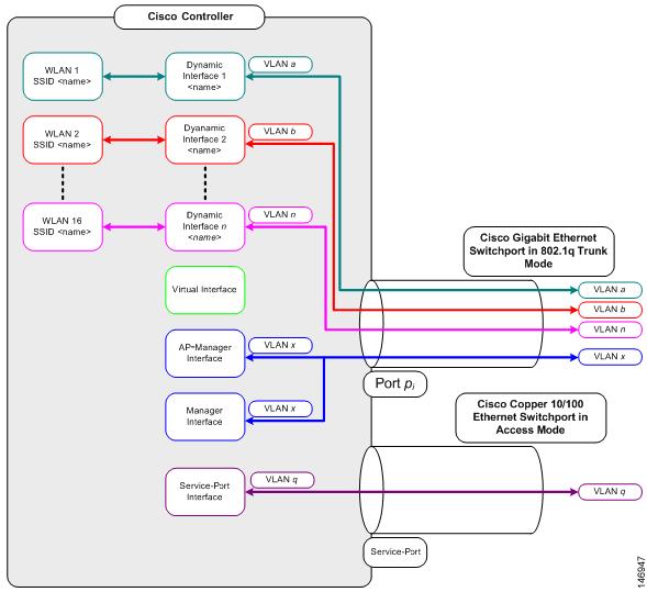
A port is a physical entity that is used for connections on the controller platform. controllers have two types of ports:
-
Distribution system ports
-
Service port
|
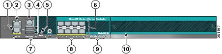
1 |
Redundant port (RJ-45) |
6 |
SFP distribution system ports 1–8 |
||
|
2 |
Service port (RJ-45) |
7 |
Management port LEDs |
||
|
3 |
Console port (RJ-45) |
8 |
SFP distribution port Link and Activity LEDs |
||
|
4 |
USB ports 0 and 1 (Type A) |
9 |
Power supply (PS1 and PS2), System (SYS), and Alarm (ALM) LEDs |
||
|
5 |
Console port (Mini USB Type B)
|
10 |
Expansion module slot |
For more information about Cisco Unified Wireless Network Protocol and Port Matrix, see http://www.cisco.com/c/en/us/support/docs/wireless/5500-series-wireless-controllers/113344-cuwn-ppm.html.
 Note |
For a comparison of ports in different controllers, see https://www.cisco.com/c/en/us/products/wireless/wireless-lan-controller/product-comparison.html. |
This section contains the following subsections:

 Feedback