Ports
A port is a physical entity that is used for connections on the controller platform. controllers have two types of ports:
-
Distribution system ports
-
Service port
|
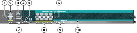
1 |
Redundant port (RJ-45) |
6 |
SFP distribution system ports 1–8 |
||
|
2 |
Service port (RJ-45) |
7 |
Management port LEDs |
||
|
3 |
Console port (RJ-45) |
8 |
SFP distribution port Link and Activity LEDs |
||
|
4 |
USB ports 0 and 1 (Type A) |
9 |
Power supply (PS1 and PS2), System (SYS), and Alarm (ALM) LEDs |
||
|
5 |
Console port (Mini USB Type B)
|
10 |
Expansion module slot |
For more information about Cisco Unified Wireless Network Protocol and Port Matrix, see http://www.cisco.com/c/en/us/support/docs/wireless/5500-series-wireless-controllers/113344-cuwn-ppm.html.
 Note |
For a comparison of ports in different controllers, see https://www.cisco.com/c/en/us/products/wireless/wireless-lan-controller/product-comparison.html. |
This section contains the following subsections:
Distribution System Ports
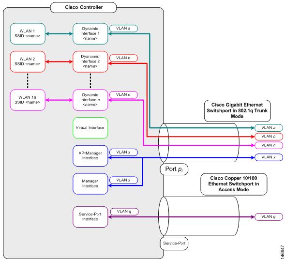
A distribution system port connects the controller to a neighbor switch and serves as the data path between these two devices.
Restrictions for Configuring Distribution System Ports
-
Each distribution system port is, by default, an 802.1Q VLAN trunk port. The VLAN trunking characteristics of the port are not configurable.
Note
Some controllers support link aggregation (LAG), which bundles all of the controller’s distribution system ports into a single 802.3ad port channel. Cisco 5508 Wireless Controllers support LAG, and LAG is enabled automatically on the controllers within the Cisco WiSM2.
-
Controller configuration in access mode is not supported. We recommend that you configure controllers in trunk mode when you configure controller ports on a switch.
-
If an IPv6 packet is destined to controller management IPv6 address and the client VLAN is different from the controller management VLAN, then the IPv6 packet is switched out of the controller box. If the same IPv6 packet comes as a network packet to the controller, management access is not denied.
Service Port
The service port can be used management purposes, primarily for out-of-band management. However, AP management traffic is not possible across the service port. In most cases, the service port is used as a "last resort" means of accessing the controller GUI for management purposes. For example, in the case where the system distribution ports on the controller are down or their communication to the wired network is otherwise degraded.
The service port is controlled by the service-port interface and is reserved for out-of-band management of the controller and system recovery and maintenance in the event of a network failure. It is also the only port that is active when the controller is in boot mode. The service port is not capable of carrying 802.1Q tags, so it must be connected to an access port on the neighbor switch. Use of the service port is optional.
Service ports are not intended for high volume of traffic. We recommend that you use the management interface through the system distribution ports (dedicated or LAG).
Service ports can be used for SNMP polling.
Note |
The service port is not auto-sensing. You must use the correct straight-through or crossover Ethernet cable to communicate with the service port. |
 Caution |
Do not configure wired clients in the same VLAN or subnet of the service port of the controller on the network. If you configure wired clients on the same subnet or VLAN as the service port, it is not possible to access the management interface of the controller. We recommend that you place the service port in a VLAN or a subnet that is dedicated to out-of-band management. |
Note |
For Cisco 5520 and 8540 Wireless Controllers, the disabling of administrative mode of the port does not physically disable the port. Only the packets are blocked due to which switchover does not happen. |
For information about service ports in the applicable controllers, see the respective controller documentation:
Configuring Ports (GUI)
The controller’s ports are configured with factory-default settings designed to make the controllers’ ports operational without additional configuration. However, you can view the status of the controller’s ports and edit their configuration parameters at any time.
Procedure
| Step 1 |
Choose to open the Ports page. This page shows the current configuration for each of the controller’s ports. If you want to change the settings of any port, click the number for that specific port. The Port > Configure page appears.
The following show the current status of the port:
The following is a list of the port’s configurable parameters.
|
||||||||
| Step 2 |
Click Apply. |
||||||||
| Step 3 |
Click Save Configuration. |
||||||||
| Step 4 |
Click Back to return to the Ports page and review your changes. |
||||||||
| Step 5 |
Repeat this procedure for each additional port that you want to configure. |
Configuring Ports (CLI)
The controller’s ports are configured with factory-default settings designed to make the controllers’ ports operational without additional configuration. However, you can view the status of the controller’s ports and edit their configuration parameters at any time.
Procedure
| Step 1 |
Configure the administrative mode for a specific port or all ports by entering this command: config port adminmode {port | all} {enable | disable} |
| Step 2 |
Configure the up and down link traps for a specific port or all ports by entering this command: config port linktrap {port | all} {enable | disable} |
| Step 3 |
Configure the maximum speed for a port by entering this command: config port maxspeed port {1000 | 2500 | 5000}
|
| Step 4 |
Configure Power over Ethernet for a specific port or all ports by entering this command: config port power {port | all} {enable | disable} |


 Feedback