Summary of Cisco 8540 Wireless Controller Features
|
Feature |
Description |
|---|---|
|
Chassis Height |
Two rack-unit (2RU) |
|
Throughput |
40 Gbps |
|
AP Support |
6000 |
|
Client Support |
64000 |
|
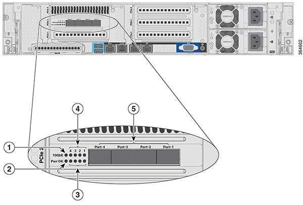
Data Ports |
4x SFP+ |
|
Storage |
Dual SSD with Hardware RAID |
|
Storage Temperature |
–40 to 149°F (–40 to 65°C) |
|
Operating Temperature |
41 to 104°F (5 to 40°C) |
|
Operating Humidity |
10 – 90% (noncondensing) |
|
Power Options |
1200 W AC, 930 W DC Redundant PSUs |


 Feedback