IPv4 ACLs

Information about Network Security with ACLs

This chapter describes how to configure network security on the switch by using access control lists (ACLs), which in commands and tables are also referred to as access lists.

ACL Overview

Packet filtering can help limit network traffic and restrict network use by certain users or devices. ACLs filter traffic as it passes through a controller and permit or deny packets crossing specified interfaces. An ACL is a sequential collection of permit and deny conditions that apply to packets. When a packet is received on an interface, the switch compares the fields in the packet against any applied ACLs to verify that the packet has the required permissions to be forwarded, based on the criteria specified in the access lists. One by one, it tests packets against the conditions in an access list. The first match decides whether the controller accepts or rejects the packets. Because the controller stops testing after the first match, the order of conditions in the list is critical. If no conditions match, the controller rejects the packet. If there are no restrictions, the controller forwards the packet; otherwise, the controller drops the packet. The controller can use ACLs on all packets it forwards. There is implcit any host deny deny rule.

You configure access lists on a controller to provide basic security for your network. If you do not configure ACLs, all packets passing through the switch could be allowed onto all parts of the network. You can use ACLs to control which hosts can access different parts of a network or to decide which types of traffic are forwarded or blocked at router interfaces. For example, you can allow e-mail traffic to be forwarded but not Telnet traffic.

Access Control Entries

An ACL contains an ordered list of access control entries (ACEs). Each ACE specifies permit or deny and a set of conditions the packet must satisfy in order to match the ACE. The meaning of permit or deny depends on the context in which the ACL is used.


Note


The maximum number of ACEs that can be applied under an access policy (ACL) for central switching is 256 ACEs. The maximum number of ACEs applicable for Flex Mode or Local Switching is 64 ACEs.

ACL Supported Types

The switch supports IP ACLs and Ethernet (MAC) ACLs:

  • IP ACLs filter IPv4 traffic, including TCP, User Datagram Protocol (UDP), Internet Group Management Protocol (IGMP), and Internet Control Message Protocol (ICMP).

  • Ethernet ACLs filter non-IP traffic.

This switch also supports quality of service (QoS) classification ACLs.

Supported ACLs

The controller supports three types of ACLs to filter traffic:

  • Port ACLs access-control traffic entering a Layer 2 interface. You can apply port ACLs to a Layer 2 interface in each direction to each access list type — IPv4 and MAC.

  • Router ACLs access-control routed traffic between VLANs and are applied to Layer 3 interfaces in a specific direction (inbound or outbound).

  • FQDN ACL: FQDN ACL is encoded along with IPv6 ACL and sent to AP. FQDN ACL is always a custom ACL. AP does DNS snooping and sends the IPv4 and IPv6 addresses to the controller.

ACL Precedence

When Port ACLs, and router ACLs are configured on the same switch, the filtering precedence, from greatest to least for ingress traffic is port ACL, and then router ACL. For egress traffic, the filtering precedence is router ACL, and then port ACL.

The following examples describe simple use cases:

  • When an input router ACL and input port ACL exist in a switch virtual interface (SVI), incoming packets received on ports to which a port ACL is applied are filtered by the port ACL. Incoming routed IP packets received on ports are filtered by the router ACL. Other packets are not filtered.

  • When an output router ACL and input port ACL exist in an SVI, incoming packets received on the ports to which a port ACL is applied are filtered by the port ACL. Outgoing routed IP packets are filtered by the router ACL. Other packets are not filtered.

Port ACLs

  • Standard IP access lists using source addresses

  • Extended IP access lists using source and destination addresses and optional protocol type information

  • MAC extended access lists using source and destination MAC addresses and optional protocol type information

The switch examines ACLs on an interface and permits or denies packet forwarding based on how the packet matches the entries in the ACL. In this way, ACLs control access to a network or to part of a network.

Figure 1. Using ACLs to Control Traffic in a Network
Using ACLs to control traffic to a network.

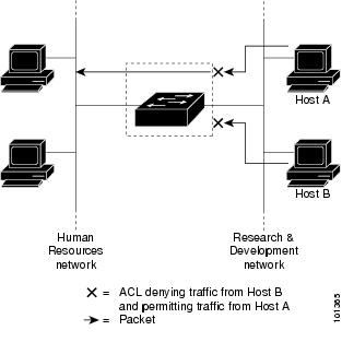
This is an example of using port ACLs to control access to a network when all workstations are in the same VLAN. ACLs applied at the Layer 2 input would allow Host A to access the Human Resources network, but prevent Host B from accessing the same network. Port ACLs can only be applied to Layer 2 interfaces in the inbound direction.

When you apply a port ACL to a trunk port, the ACL filters traffic on all VLANs present on the trunk port. When you apply a port ACL to a port with voice VLAN, the ACL filters traffic on both data and voice VLANs.

With port ACLs, you can filter IP traffic by using IP access lists and non-IP traffic by using MAC addresses. You can filter both IP and non-IP traffic on the same Layer 2 interface by applying both an IP access list and a MAC access list to the interface.


Note


You can’t apply more than one IP access list and one MAC access list to a Layer 2 interface. If an IP access list or MAC access list is already configured on a Layer 2 interface and you apply a new IP access list or MAC access list to the interface, the new ACL replaces the previously configured one.


Router ACLs

You can apply router ACLs on switch virtual interfaces (SVIs), which are Layer 3 interfaces to VLANs; on physical Layer 3 interfaces; and on Layer 3 EtherChannel interfaces. You apply router ACLs on interfaces for specific directions (inbound or outbound). You can apply one router ACL in each direction on an interface.

The switch supports these access lists for IPv4 traffic:

  • Standard IP access lists use source addresses for matching operations.

  • Extended IP access lists use source and destination addresses and optional protocol type information for matching operations.

As with port ACLs, the switch examines ACLs associated with features configured on a given interface. As packets enter the switch on an interface, ACLs associated with all inbound features configured on that interface are examined. After packets are routed and before they are forwarded to the next hop, all ACLs associated with outbound features configured on the egress interface are examined.

ACLs permit or deny packet forwarding based on how the packet matches the entries in the ACL, and can be used to control access to a network or to part of a network.

ACEs and Fragmented and Unfragmented Traffic

IP packets can be fragmented as they cross the network. When this happens, only the fragment containing the beginning of the packet contains the Layer 4 information, such as TCP or UDP port numbers, ICMP type and code, and so on. All other fragments are missing this information.

Some access control entries (ACEs) do not check Layer 4 information and therefore can be applied to all packet fragments. ACEs that do test Layer 4 information cannot be applied in the standard manner to most of the fragments in a fragmented IP packet. When the fragment contains no Layer 4 information and the ACE tests some Layer 4 information, the matching rules are modified:

  • Permit ACEs that check the Layer 3 information in the fragment (including protocol type, such as TCP, UDP, and so on) are considered to match the fragment regardless of what the missing Layer 4 information might have been.


    Note


    For TCP ACEs with L4 Ops, the fragmented packets will be dropped per RFC 1858.


  • Deny ACEs that check Layer 4 information never match a fragment unless the fragment contains Layer 4 information.

ACEs and Fragmented and Unfragmented Traffic Examples

Consider access list 102, configured with these commands, applied to three fragmented packets:


Device(config)# access-list 102 permit tcp any host 10.1.1.1 eq smtp
Device(config)# access-list 102 deny tcp any host 10.1.1.2 eq telnet
Device(config)# access-list 102 permit tcp any host 10.1.1.2
Device(config)# access-list 102 deny tcp any any


Note


In the first and second ACEs in the examples, the eq keyword after the destination address means to test for the TCP-destination-port well-known numbers equaling Simple Mail Transfer Protocol (SMTP) and Telnet, respectively.


  • Packet A is a TCP packet from host 10.2.2.2., port 65000, going to host 10.1.1.1 on the SMTP port. If this packet is fragmented, the first fragment matches the first ACE (a permit) as if it were a complete packet because all Layer 4 information is present. The remaining fragments also match the first ACE, even though they do not contain the SMTP port information, because the first ACE only checks Layer 3 information when applied to fragments. The information in this example is that the packet is TCP and that the destination is 10.1.1.1.

  • Packet B is from host 10.2.2.2, port 65001, going to host 10.1.1.2 on the Telnet port. If this packet is fragmented, the first fragment matches the second ACE (a deny) because all Layer 3 and Layer 4 information is present. The remaining fragments in the packet do not match the second ACE because they are missing Layer 4 information. Instead, they match the third ACE (a permit).

    Because the first fragment was denied, host 10.1.1.2 cannot reassemble a complete packet, so packet B is effectively denied. However, the later fragments that are permitted will consume bandwidth on the network and resources of host 10.1.1.2 as it tries to reassemble the packet.

  • Fragmented packet C is from host 10.2.2.2, port 65001, going to host 10.1.1.3, port ftp. If this packet is fragmented, the first fragment matches the fourth ACE (a deny). All other fragments also match the fourth ACE because that ACE does not check any Layer 4 information and because Layer 3 information in all fragments shows that they are being sent to host 10.1.1.3, and the earlier permit ACEs were checking different hosts.

Standard and Extended IPv4 ACLs

This section describes IP ACLs.

An ACL is a sequential collection of permit and deny conditions. One by one, the switch tests packets against the conditions in an access list. The first match determines whether the switch accepts or rejects the packet. Because the switch stops testing after the first match, the order of the conditions is critical. If no conditions match, the switch denies the packet.

The software supports these types of ACLs or access lists for IPv4:

  • Standard IP access lists use source addresses for matching operations.

  • Extended IP access lists use source and destination addresses for matching operations and optional protocol-type information for finer granularity of control.


Note


Only extended ACLs are supported while the standard ACLs are not supported.


IPv4 ACL Switch Unsupported Features

Configuring IPv4 ACLs on the switch is the same as configuring IPv4 ACLs on other Cisco switches and routers.

The following ACL-related features are not supported:

  • Non-IP protocol ACLs

  • IP accounting

  • Reflexive ACLs, URL Redirect ACLs and Dynamic ACLs are not supported.

Access List Numbers

The number you use to denote your ACL shows the type of access list that you are creating.

This lists the access-list number and corresponding access list type and shows whether or not they are supported in the switch. The switch supports IPv4 standard and extended access lists, numbers 1 to 199 and 1300 to 2699.

Table 1. Access List Numbers

Access List Number

Type

Supported

1–99

IP standard access list

Yes

100–199

IP extended access list

Yes

200–299

Protocol type-code access list

No

300–399

DECnet access list

No

400–499

XNS standard access list

No

500–599

XNS extended access list

No

600–699

AppleTalk access list

No

700–799

48-bit MAC address access list

No

800–899

IPX standard access list

No

900–999

IPX extended access list

No

1000–1099

IPX SAP access list

No

1100–1199

Extended 48-bit MAC address access list

No

1200–1299

IPX summary address access list

No

1300–1999

IP standard access list (expanded range)

Yes

2000–2699

IP extended access list (expanded range)

Yes

In addition to numbered standard and extended ACLs, you can also create standard and extended named IP ACLs by using the supported numbers. That is, the name of a standard IP ACL can be 1 to 99; the name of an extended IP ACL can be 100 to 199. The advantage of using named ACLs instead of numbered lists is that you can delete individual entries from a named list.

Numbered Standard IPv4 ACLs

When creating an ACL, remember that, by default, the end of the ACL contains an implicit deny statement for all packets that it did not find a match for before reaching the end. With standard access lists, if you omit the mask from an associated IP host address ACL specification, 0.0.0.0 is assumed to be the mask.

The switch always rewrites the order of standard access lists so that entries with host matches and entries with matches having a don’t care mask of 0.0.0.0 are moved to the top of the list, above any entries with non-zero don’t care masks. Therefore, in show command output and in the configuration file, the ACEs do not necessarily appear in the order in which they were entered.

After creating a numbered standard IPv4 ACL, you can apply it to terminal lines (virtual teletype (VTY) lines), or to interfaces.

Numbered Extended IPv4 ACLs

Although standard ACLs use only source addresses for matching, you can use extended ACL source and destination addresses for matching operations and optional protocol type information for finer granularity of control. When you are creating ACEs in numbered extended access lists, remember that after you create the ACL, any additions are placed at the end of the list. You cannot reorder the list or selectively add or remove ACEs from a numbered list.

The switch does not support dynamic or reflexive access lists. It also does not support filtering based on the type of service (ToS) minimize-monetary-cost bit.

Some protocols also have specific parameters and keywords that apply to that protocol.

You can define an extended TCP, UDP, ICMP, IGMP, or other IP ACL. The switch also supports these IP protocols:

These IP protocols are supported:

  • Authentication Header Protocol (ahp )

  • Encapsulation Security Payload (esp )

  • Enhanced Interior Gateway Routing Protocol (eigrp )

  • generic routing encapsulation (gre )

  • Internet Control Message Protocol (icmp )

  • Internet Group Management Protocol (igmp )

  • any Interior Protocol (ip )

  • IP in IP tunneling (ipinip )

  • KA9Q NOS-compatible IP over IP tunneling (nos )

  • Open Shortest Path First routing (ospf )

  • Payload Compression Protocol (pcp )

  • Protocol-Independent Multicast (pim )

  • Transmission Control Protocol (tcp )

  • User Datagram Protocol (udp )

Named IPv4 ACLs

You can identify IPv4 ACLs with an alphanumeric string (a name) rather than a number. You can use named ACLs to configure more IPv4 access lists in a router than if you were to use numbered access lists. If you identify your access list with a name rather than a number, the mode and command syntax are slightly different. However, at times, not all commands that use IP access lists accept a named access list.


Note


The name you give to a standard or extended ACL can also be a number in the supported range of access list numbers. That is, the name of a standard IP ACL can be 1 to 99 and . The advantage of using named ACLs instead of numbered lists is that you can delete individual entries from a named list.


Consider these guidelines before configuring named ACLs:

  • Numbered ACLs are also available.

  • A standard ACL and an extended ACL cannot have the same name.

ACL Logging

The controller software can provide logging messages about packets permitted or denied by a standard IP access list. That is, any packet that matches the ACL causes an informational logging message about the packet to be sent to the console. The level of messages logged to the console is controlled by the logging console commands controlling the syslog messages.


Note


Because routing is done in hardware and logging is done in software, if a large number of packets match a permit or deny ACE containing a log keyword, the software might not be able to match the hardware processing rate, and not all packets will be logged.


The first packet that triggers the ACL causes a logging message right away, and subsequent packets are collected over 5-minute intervals before they appear or logged. The logging message includes the access list number, whether the packet was permitted or denied, the source IP address of the packet, and the number of packets from that source permitted or denied in the prior 5-minute interval.


Note


The logging facility might drop some logging message packets if there are too many to be handled or if there is more than one logging message to be handled in 1 second. This behavior prevents the router from crashing due to too many logging packets. Therefore, the logging facility should not be used as a billing tool or an accurate source of the number of matches to an access list.

Hardware and Software Treatment of IP ACLs

ACL processing is performed in hardware. If the hardware reaches its capacity to store ACL configurations, all packets on that interface are dropped.

The ACL scale for controllers is as follows:

  • Cisco Catalyst 9800-40 Wireless Controller, Cisco Catalyst 9800-L Wireless Controller, Cisco Catalyst 9800-CL Wireless Controller (small and medium) support 128 ACLs with 128 Access List Entries (ACEs).

  • Cisco Catalyst 9800-80 Wireless Controller and Cisco Catalyst 9800-CL Wireless Controller (large) support 256 ACLs and 256 ACEs.

  • FlexConnect and Fabric mode APs support 96 ACLs.


Note


If an ACL configuration cannot be implemented in the hardware due to an out-of-resource condition on the controller, then only the traffic in that VLAN arriving on that controller is affected.


When you enter the show ip access-lists privileged EXEC command, the match count displayed does not account for packets that are access controlled in hardware. Use the privileged EXEC command to obtain some basic hardware ACL statistics for switched and routed packets.

IPv4 ACL Interface Considerations

For inbound ACLs, after receiving a packet, the controller checks the packet against the ACL. If the ACL permits the packet, the controller continues to process the packet. If the ACL rejects the packet, the controller discards the packet.

For outbound ACLs, after receiving and routing a packet to a controlled interface, the controller checks the packet against the ACL. If the ACL permits the packet, the controller sends the packet. If the ACL rejects the packet, the controller discards the packet.

If an undefined ACL has nothing listed in it, it is an empty access list.

Restrictions for Configuring IPv4 Access Control Lists

The following are restrictions for configuring network security with ACLs:

General Network Security

The following are restrictions for configuring network security with ACLs:

  • A standard ACL and an extended ACL cannot have the same name.

  • Though visible in the command-line help strings, AppleTalk is not supported as a matching condition for the deny and permit MAC access-list configuration mode commands.

  • DNS traffic is permitted by default with or without ACL entries for clients that are awaiting web authentication.

IPv4 ACL Network Interfaces

The following restrictions apply to IPv4 ACLs to network interfaces:

  • When controlling access to an interface, you can use a named or numbered ACL.

  • You do not have to enable routing to apply ACLs to Layer 2 interfaces.

MAC ACLs on a Layer 2 Interface

After you create a MAC ACL, you can apply it to a Layer 2 interface to filter non-IP traffic coming in that interface. When you apply the MAC ACL, consider these guidelines:

  • You can apply no more than one IP access list and one MAC access list to the same Layer 2 interface. The IP access list filters only IP packets, and the MAC access list filters non-IP packets.

  • A Layer 2 interface can have only one MAC access list. If you apply a MAC access list to a Layer 2 interface that has a MAC ACL configured, the new ACL replaces the previously configured one.


Note


The mac access-group interface configuration command is only valid when applied to a physical Layer 2 interface. You cannot use the command on EtherChannel port channels.


IP Access List Entry Sequence Numbering

  • This feature does not support dynamic, reflexive, or firewall access lists.

How to Configure ACLs

Configuring IPv4 ACLs (GUI)

Procedure


Step 1

Choose Configuration > Security > ACL.

Step 2

Click Add.

Step 3

In the Add ACL Setup dialog box, enter the following parameters.

  • ACL Name: Enter the name for the ACL.

  • ACL Type: IPv4 Standard.

  • Sequence: Enter the sequence number.

  • Action: Choose Permit or Deny the packet flow from the drop-down list.

  • Source Type: Choose any, Host or Network from which the packet is sent.

  • Log: Enable or disable logging.

Step 4

Click Add.

Step 5

Add the rest of the rules and click Apply to Device.


Configuring IPv4 ACLs

Follow the procedure given below to use IP ACLs on the switch:

Procedure


Step 1

Create an ACL by specifying an access list number or name and the access conditions.

Step 2

Apply the ACL to interfaces or terminal lines..


Creating a Numbered Standard ACL (GUI)

Procedure


Step 1

Choose Configuration > Security > ACL.

Step 2

On the ACL page, click Add.

Step 3

In the Add ACL Setup window, enter the following parameters.

  • ACL Name: Enter the name for the ACL.

  • ACL Type: IPv4 Standard.

  • Sequence: Enter the sequence number.

  • Action: Choose Permit or Deny access from the drop-down list.

  • Source Type: Choose any, Host or Network

  • Log: Enable or disable logging, this is limited to ACLs associated to Layer 3 interface only.

Step 4

Click Add.

Step 5

Click Save & Apply to Device.


Creating a Numbered Standard ACL (CLI)

Follow the procedure given below to create a numbered standard ACL:

Procedure

  Command or Action Purpose

Step 1

enable

Example:


Device> enable

Enables privileged EXEC mode. Enter your password if prompted.

Step 2

configure terminal

Example:


Device# configure terminal

Enters global configuration mode.

Step 3

access-list access-list-number {deny | permit} source source-wildcard ]

Example:


Device(config)# access-list 2 deny your_host

Defines a standard IPv4 access list by using a source address and wildcard.

The access-list-number is a decimal number from 1 to 99 or 1300 to 1999.

Enter deny or permit to specify whether to deny or permit access if conditions are matched.

The source is the source address of the network or host from which the packet is being sent specified as:

  • The 32-bit quantity in dotted-decimal format.

  • The keyword any as an abbreviation for source and source-wildcard of 0.0.0.0 255.255.255.255. You do not need to enter a source-wildcard.

  • The keyword host as an abbreviation for source and source-wildcard of source 0.0.0.0.

(Optional) The source-wildcard applies wildcard bits to the source.

Note


Logging is supported only on ACLs attached to Layer 3 interfaces.

Step 4

end

Example:


Device(config)# end

Returns to privileged EXEC mode.

Step 5

show running-config

Example:


Device# show running-config

Verifies your entries.

Step 6

copy running-config startup-config

Example:


Device# copy running-config startup-config

(Optional) Saves your entries in the configuration file.

Creating a Numbered Extended ACL (GUI)

Procedure


Step 1

Choose Configuration > Security > ACL.

Step 2

On the ACL page, click Add.

Step 3

In the Add ACL Setup window, enter the following parameters.

  • ACL Name: Enter the name for the ACL.

  • ACL Type: IPv4 Extended.

  • Sequence: Enter the sequence number.

  • Action: Choose Permit or Deny the packet flow from the drop-down list.

  • Source Type: Choose any, Host or Network from which the packet is sent.

  • Destination Type: Choose any, Host or Network to which the packet is sent.

  • Protocol: Choose a protocol from the drop-down list.

  • Log: Enable or disable logging.

  • DSCP: Enter to match packets with the DSCP value

Step 4

Click Add.

Step 5

Click Save & Apply to Device.


Creating a Numbered Extended ACL (CLI)

Follow the procedure given below to create a numbered extended ACL:

Procedure

  Command or Action Purpose

Step 1

configure terminal

Example:


Device# configure terminal

Enters global configuration mode.

Step 2

access-list access-list-number 
{deny | permit} protocol source source-wildcard destination destination-wildcard [precedence precedence] [tos tos] [fragments] [time-range time-range-name] [dscp dscp]

Example:


Device(config)# access-list 101 permit ip host 10.1.1.2 any precedence 0 tos 0 log

Defines an extended IPv4 access list and the access conditions.

The access-list-number is a decimal number from 100 to 199 or 2000 to 2699.

Enter deny or permit to specify whether to deny or permit the packet if conditions are matched.

For protocol , enter the name or number of an P protocol: ahp , eigrp , esp , gre , icmp , igmp , igrp , ip , ipinip , nos , ospf , pcp , pim , tcp , or udp , or an integer in the range 0 to 255 representing an IP protocol number. To match any Internet protocol (including ICMP, TCP, and UDP), use the keyword ip .

Note

 
This step includes options for most IP protocols. For additional specific parameters for TCP, UDP, ICMP, and IGMP, see the following steps.

The source is the number of the network or host from which the packet is sent.

The source-wildcard applies wildcard bits to the source.

The destination is the network or host number to which the packet is sent.

The destination-wildcard applies wildcard bits to the destination.

Source, source-wildcard, destination, and destination-wildcard can be specified as:

  • The 32-bit quantity in dotted-decimal format.

  • The keyword any for 0.0.0.0 255.255.255.255 (any host).

  • The keyword host for a single host 0.0.0.0.

The other keywords are optional and have these meanings:

  • precedence —Enter to match packets with a precedence level specified as a number from 0 to 7 or by name: routine (0), priority (1), immediate (2), flash (3), flash-override (4), critical (5), internet (6), network (7).

  • fragments —Enter to check non-initial fragments.

  • tos —Enter to match by type of service level, specified by a number from 0 to 15 or a name: normal (0), max-reliability (2), max-throughput (4), min-delay (8).

  • time-range —Specify the time-range name.

  • dscp —Enter to match packets with the DSCP value specified by a number from 0 to 63, or use the question mark (?) to see a list of available values.

    Note


    Your controller must support the ability to:

Note


If you enter a dscp value, you cannot enter tos or precedence . You can enter both a tos and a precedence value with no dscp .

Step 3

access-list access-list-number {deny | permit} tcp source source-wildcard [operator port] destination destination-wildcard [operator port] [precedence precedence] [tos tos] [fragments] [time-range time-range-name] [dscp dscp] [flag]

Example:


Device(config)# access-list 101 permit tcp any any eq 500

Defines an extended TCP access list and the access conditions.

The parameters are the same as those described for an extended IPv4 ACL, with these exceptions:

(Optional) Enter an operator and port to compare source (if positioned after source source-wildcard ) or destination (if positioned after destination destination-wildcard ) port. Possible operators include eq (equal), gt (greater than), lt (less than), neq (not equal), and range (inclusive range). Operators require a port number (range requires two port numbers separated by a space).

Enter the port number as a decimal number (from 0 to 65535) or the name of a TCP port. Use only TCP port numbers or names when filtering TCP.

The other optional keywords have these meanings:

  • flag —Enter one of these flags to match by the specified TCP header bits: ack (acknowledge), fin (finish), psh (push), rst (reset), syn (synchronize), or urg (urgent).

Step 4

access-list access-list-number 
{deny | permit} udp source source-wildcard [operator port] destination destination-wildcard [operator port] [precedence precedence] [tos tos] [fragments] [time-range time-range-name] [dscp dscp]

Example:


Device(config)# access-list 101 permit udp any any eq 100

(Optional) Defines an extended UDP access list and the access conditions.

The UDP parameters are the same as those described for TCP except that the [operator [port]] port number or name must be a UDP port number or name, and the flag not valid for UDP.

Step 5

access-list access-list-number 
{deny | permit} icmp source source-wildcard destination destination-wildcard [icmp-type | [[icmp-type icmp-code] | [icmp-message]] [precedence precedence] [tos tos] [fragments] [time-range time-range-name] [dscp dscp]

Example:


Device(config)# access-list 101 permit icmp any any 200

Defines an extended ICMP access list and the access conditions.

The ICMP parameters are the same as those described for most IP protocols in an extended IPv4 ACL, with the addition of the ICMP message type and code parameters. These optional keywords have these meanings:

  • icmp-type—Enter to filter by ICMP message type, a number from 0 to 255.

  • icmp-code—Enter to filter ICMP packets that are filtered by the ICMP message code type, a number from 0 to 255.

  • icmp-message—Enter to filter ICMP packets by the ICMP message type name or the ICMP message type and code name.

Step 6

access-list access-list-number 
{deny | permit} igmp source source-wildcard destination destination-wildcard [igmp-type] [precedence precedence] [tos tos] [fragments] [time-range time-range-name] [dscp dscp]

Example:


Device(config)# access-list 101 permit igmp any any 14

(Optional) Defines an extended IGMP access list and the access conditions.

The IGMP parameters are the same as those described for most IP protocols in an extended IPv4 ACL, with this optional parameter.

igmp-type—To match IGMP message type, enter a number from 0 to 15, or enter the message name: dvmrp , host-query , host-report , pim , or trace .

Step 7

end

Example:


Device(config)# end

Returns to privileged EXEC mode.

Creating Named Standard ACLs (GUI)

Procedure


Step 1

Click Configuration > Security > ACL.

Step 2

Click Add to create a new ACL setup.

Step 3

In the Add ACL Setup window, enter the following parameters.

  • ACL Name: Enter the name for the ACL

  • ACL Type: IPv4 Standard

  • Sequence: The valid range is between 1 and 99 or 1300 and 1999

  • Action: Choose Permit or Deny access from the drop-down list.

  • Source Type: Choose any, Host or Network

  • Log: Enable or disable logging, this is limited to ACLs associated to Layer 3 interface only.

Step 4

Click Add to add the rule.

Step 5

Click Save & Apply to Device.


Creating Named Standard ACLs

Follow the procedure given below to create a standard ACL using names:

Procedure

  Command or Action Purpose

Step 1

enable

Example:


Device> enable

Enables privileged EXEC mode. Enter your password if prompted.

Step 2

configure terminal

Example:


Device# configure terminal

Enters global configuration mode.

Step 3

ip access-list standard name

Example:


Device(config)# ip access-list standard 20

Defines a standard IPv4 access list using a name, and enter access-list configuration mode.

The name can be a number from 1 to 99.

Step 4

Use one of the following:

  • deny {source [source-wildcard] | host source | any} [log]
  • permit {source [source-wildcard] | host source | any} [log]

Example:


Device(config-std-nacl)# deny 192.168.0.0 0.0.255.255 255.255.0.0 0.0.255.255

or


Device(config-std-nacl)# permit 10.108.0.0 0.0.0.0 255.255.255.0 0.0.0.0

In access-list configuration mode, specify one or more conditions denied or permitted to decide if the packet is forwarded or dropped.

  • host source —A source and source wildcard of source 0.0.0.0.

  • any —A source and source wildcard of 0.0.0.0 255.255.255.255.

Step 5

end

Example:


Device(config-std-nacl)# end

Returns to privileged EXEC mode.

Step 6

show running-config

Example:


Device# show running-config

Verifies your entries.

Step 7

copy running-config startup-config

Example:


Device# copy running-config startup-config

(Optional) Saves your entries in the configuration file.

Creating Extended Named ACLs (GUI)

Procedure


Step 1

Choose Configuration > Security > ACL.

Step 2

Click Add.

Step 3

In the Add ACL Setup window, enter the following parameters.

  • ACL Name: Enter the name for the ACL.

  • ACL Type: IPv4 Extended.

  • Sequence: Enter the sequence number.

  • Action: Choose Permit or Deny the packet flow from the drop-down list.

  • Source Type: Choose any, Host or Network from which the packet is sent.

  • Destination Type: Choose any, Host or Network to which the packet is sent.

  • Protocol: Choose a protocol from the drop-down list.

  • Log: Enable or disable logging.

  • DSCP: Enter to match packets with the DSCP value

Step 4

Click Add.

Step 5

Add the rest of the rules and click Apply to Device.


Creating Extended Named ACLs

Follow the procedure given below to create an extended ACL using names:

Procedure

  Command or Action Purpose

Step 1

enable

Example:


Device> enable

Enables privileged EXEC mode. Enter your password if prompted.

Step 2

configure terminal

Example:


Device# configure terminal

Enters global configuration mode.

Step 3

ip access-list extended name

Example:


Device(config)# ip access-list extended 150

Defines an extended IPv4 access list using a name, and enter access-list configuration mode.

The name can be a number from 100 to 199.

Step 4

{deny | permit} protocol {source [source-wildcard] | host source | any} {destination [destination-wildcard] | host destination | any} [precedence precedence] [tos tos] [log] [time-range time-range-name]

Example:


Device(config-ext-nacl)# permit 0 any any

In access-list configuration mode, specify the conditions allowed or denied. Use the log keyword to get access list logging messages, including violations.

  • host source —A source and source wildcard of source 0.0.0.0.

  • host destintation —A destination and destination wildcard of destination 0.0.0.0.

  • any—A source and source wildcard or destination and destination wildcard of 0.0.0.0 255.255.255.255.

Step 5

end

Example:


Device(config-ext-nacl)# end

Returns to privileged EXEC mode.

Step 6

show running-config

Example:


Device# show running-config

Verifies your entries.

Step 7

copy running-config startup-config

Example:


Device# copy running-config startup-config

(Optional) Saves your entries in the configuration file.

When you are creating extended ACLs, remember that, by default, the end of the ACL contains an implicit deny statement for everything if it did not find a match before reaching the end. For standard ACLs, if you omit the mask from an associated IP host address access list specification, 0.0.0.0 is assumed to be the mask.

After you create an ACL, any additions are placed at the end of the list. You cannot selectively add ACL entries to a specific ACL. However, you can use no permit and no deny access-list configuration mode commands to remove entries from a named ACL.

Being able to selectively remove lines from a named ACL is one reason you might use named ACLs instead of numbered ACLs.

What to do next

After creating a named ACL, you can apply it to interfaces or to VLANs.

Applying an IPv4 ACL to an Interface (GUI)

Procedure


Step 1

Choose Configuration > Security > ACL.

Step 2

Click Associating Interfaces.

Step 3

Choose the interface from the Available Interfaces list to view its ACL details on the right-hand side. You can change the ACL details, if required.

Step 4

Click Save & Apply to Device.


Applying an IPv4 ACL to an Interface (CLI)

This section describes how to apply IPv4 ACLs to network interfaces.

Beginning in privileged EXEC mode, follow the procedure given below to control access to an interface:

Procedure

  Command or Action Purpose

Step 1

configure terminal

Example:


Device# configure terminal

Enters global configuration mode.

Step 2

interface interface-id

Example:


Device(config)# 

Identifies a specific interface for configuration, and enter interface configuration mode.

The interface can be a Layer 2 interface (port ACL), or a Layer 3 interface (router ACL).

Step 3

ip access-group {access-list-number | name} {in | out}

Example:


Device(config-if)# ip access-group 2 in

Controls access to the specified interface.

Step 4

end

Example:


Device(config-if)# end

Returns to privileged EXEC mode.

Step 5

show running-config

Example:


Device# show running-config

Displays the access list configuration.

Step 6

copy running-config startup-config

Example:


Device# copy running-config startup-config

(Optional) Saves your entries in the configuration file.

Applying ACL to Policy Profile (GUI)

Procedure


Step 1

Choose Configuration > Tags & Profiles > Policy.

Step 2

On the Policy Profile page, click Add.

Step 3

In the Add Policy Profile window, click Access Policies tab.

Step 4

In the WLAN ACL area, choose the IPv4 ACL from the IPv4 ACL drop-down list.

Step 5

Click Apply to Device.


Applying ACL to Policy Profile

Procedure

  Command or Action Purpose

Step 1

configure terminal

Example:

Device# configure terminal

Enters global configuration mode.

Step 2

wireless profile policy profile-policy

Example:

Device(config)# wireless profile policy profile-policy

Configures a WLAN policy profile and enters wireless policy configuration mode.

Step 3

ipv4 acl acl-name

Example:

Device(config-wireless-policy)# ipv4 acl test-acl

Configures an IPv4 ACL.

Step 4

end

Example:

Device(config-wireless-policy)# end

Returns to privileged EXEC mode. Alternatively, you can also press Ctrl-Z to exit global configuration mode.

Configuration Examples for ACLs

Examples: Including Comments in ACLs

You can use the remark keyword to include comments (remarks) about entries in any IP standard or extended ACL. The remarks make the ACL easier for you to understand and scan. Each remark line is limited to 100 characters.

The remark can go before or after a permit or deny statement. You should be consistent about where you put the remark so that it is clear which remark describes which permit or deny statement. For example, it would be confusing to have some remarks before the associated permit or deny statements and some remarks after the associated statements.

To include a comment for IP numbered standard or extended ACLs, use the access-list access-list number remark remark global configuration command. To remove the remark, use the no form of this command.

In this example, the workstation that belongs to Jones is allowed access, and the workstation that belongs to Smith is not allowed access:


Device(config)# access-list 1 remark Permit only Jones workstation through
Device(config)# access-list 1 permit 171.69.2.88
Device(config)# access-list 1 remark Do not allow Smith through
Device(config)# access-list 1 deny 171.69.3.13

For an entry in a named IP ACL, use the remark access-list configuration command. To remove the remark, use the no form of this command.

In this example, the Jones subnet is not allowed to use outbound Telnet:


Device(config)# ip access-list extended telnetting
Device(config-ext-nacl)# remark Do not allow Jones subnet to telnet out
Device(config-ext-nacl)# deny tcp host 171.69.2.88 any eq telnet

Examples: Applying an IPv4 ACL to a Policy Profile in a Wireless Environment

This example shows how to apply an IPv4 ACL to a Policy Profile in a Wireless environment.


Note


All IPv4 ACLs must be associated to a policy profile.


This example uses extended ACLs to permit TCP traffic.

  1. Creating an IPv4 ACL.

    Device(config)# ip access-list extended <acl-name>
    Device(config-ext-nacl)# 10 permit ip any 10.193.48.224 0.0.0.31
    Device (config-ext-nacl)# 20 permit ip any any
  2. Applying the IPv4 ACL to a policy profile.

    Device(config)# wireless profile policy <policy-profile-name>
    Device(config-wireless-policy)# shutdown
    Device(config-wireless-policy)# ipv4 acl <acl-name>
    Device(config-wireless-policy)# no shutdown
    

IPv4 ACL Configuration Examples

This section provides examples of configuring and applying IPv4 ACLs. For detailed information about compiling ACLs, see the Cisco IOS Security Configuration Guide, Release 12.4 and to the Configuring IP Services” section in the “IP Addressing and Services” chapter of the Cisco IOS IP Configuration Guide, Release 12.4.

ACLs in a Small Networked Office

Figure 2. Using Router ACLs to Control Traffic
Using Router ACLs to Control Traffic

This shows a small networked office environment with routed Port 2 connected to Server A, containing benefits and other information that all employees can access, and routed Port 1 connected to Server B, containing confidential payroll data. All users can access Server A, but Server B has restricted access.

Use router ACLs to do this in one of two ways:

  • Create a standard ACL, and filter traffic coming to the server from Port 1.

  • Create an extended ACL, and filter traffic coming from the server into Port 1.

Examples: ACLs in a Small Networked Office

This example uses a standard ACL to filter traffic coming into Server B from a port, permitting traffic only from Accounting’s source addresses 172.20.128.64 to 172.20.128.95. The ACL is applied to traffic coming out of routed Port 1 from the specified source address.


Device(config)# access-list 6 permit 172.20.128.64 0.0.0.31
Device(config)# end
Device# how access-lists
Standard IP access list 6
    10 permit 172.20.128.64, wildcard bits 0.0.0.31
Device(config)# interface gigabitethernet1/0/1
Device(config-if)# ip access-group 6 out

This example uses an extended ACL to filter traffic coming from Server B into a port, permitting traffic from any source address (in this case Server B) to only the Accounting destination addresses 172.20.128.64 to 172.20.128.95. The ACL is applied to traffic going into routed Port 1, permitting it to go only to the specified destination addresses. Note that with extended ACLs, you must enter the protocol (IP) before the source and destination information.


Device(config)# access-list 106 permit ip any 172.20.128.64 0.0.0.31
Device(config)# end
Device# show access-lists
Extended IP access list 106
    10 permit ip any 172.20.128.64 0.0.0.31
Device(config)# interface gigabitethernet1/0/1
Device(config-if)# ip access-group 106 in

Example: Numbered ACLs

In this example, network 10.0.0.0 is a Class A network whose second octet specifies a subnet; that is, its subnet mask is 255.255.0.0. The third and fourth octets of a network 10.0.0.0 address specify a particular host. Using access list 2, the switch accepts one address on subnet 48 and reject all others on that subnet. The last line of the list shows that the switch accepts addresses on all other network 10.0.0.0 subnets. The ACL is applied to packets entering a port.


Device(config)# access-list 2 permit 10.48.0.3
Device(config)# access-list 2 deny 10.48.0.0 0.0.255.255
Device(config)# access-list 2 permit 10.0.0.0 0.255.255.255 
Device(config)# 
Device(config-if)# ip access-group 2 in

Examples: Extended ACLs

In this example, the first line permits any incoming TCP connections with destination ports greater than 1023. The second line permits incoming TCP connections to the Simple Mail Transfer Protocol (SMTP) port of host 128.88.1.2. The third line permits incoming ICMP messages for error feedback.


Device(config)# access-list 102 permit tcp any 128.88.0.0 0.0.255.255 gt 1023
Device(config)# access-list 102 permit tcp any host 128.88.1.2 eq 25
Device(config)# access-list 102 permit icmp any any
Device(config)# 
Device(config-if)# ip access-group 102 in

In this example, suppose that you have a network connected to the Internet, and you want any host on the network to be able to form TCP connections to any host on the Internet. However, you do not want IP hosts to be able to form TCP connections to hosts on your network, except to the mail (SMTP) port of a dedicated mail host.

SMTP uses TCP port 25 on one end of the connection and a random port number on the other end. The same port numbers are used throughout the life of the connection. Mail packets coming in from the Internet have a destination port of 25. Because the secure system of the network always accepts mail connections on port 25, the incoming are separately controlled.


Device(config)# access-list 102 permit tcp any 128.88.0.0 0.0.255.255 eq 23
Device(config)# access-list 102 permit tcp any 128.88.0.0 0.0.255.255 eq 25
Device(config)# 
Device(config-if)# ip access-group 102 in

Examples: Named ACLs

Creating named standard and extended ACLs

This example creates a standard ACL named internet_filter and an extended ACL named marketing_group. The internet_filter ACL allows all traffic from the source address 1.2.3.4.


Device(config)# ip access-list standard Internet_filter
Device(config-ext-nacl)# permit 1.2.3.4
Device(config-ext-nacl)# exit

The marketing_group ACL allows any TCP Telnet traffic to the destination address and wildcard 171.69.0.0 0.0.255.255 and denies any other TCP traffic. It permits ICMP traffic, denies UDP traffic from any source to the destination address range 171.69.0.0 through 179.69.255.255 with a destination port less than 1024, denies any other IP traffic, and provides a log of the result.


Device(config)# ip access-list extended marketing_group
Device(config-ext-nacl)# permit tcp any 171.69.0.0 0.0.255.255 eq telnet
Device(config-ext-nacl)# deny tcp any any
Device(config-ext-nacl)# permit icmp any any
Device(config-ext-nacl)# deny udp any 171.69.0.0 0.0.255.255 lt 1024
Device(config-ext-nacl)# deny ip any any log
Device(config-ext-nacl)# exit

The Internet_filter ACL is applied to outgoing traffic and the marketing_group ACL is applied to incoming traffic on a Layer 3 port.


Device(config)# interface gigabitethernet3/0/1

Device(config-if)# ip address 2.0.5.1 255.255.255.0
Device(config-if)# ip access-group Internet_filter out
Device(config-if)# ip access-group marketing_group in

Deleting individual ACEs from named ACLs

This example shows how you can delete individual ACEs from the named access list border-list:


Device(config)# ip access-list extended border-list
Device(config-ext-nacl)# no permit ip host 10.1.1.3 any

Monitoring IPv4 ACLs

You can monitor IPv4 ACLs by displaying the ACLs that are configured on the switch, and displaying the ACLs that have been applied to interfaces and VLANs.

When you use the ip access-group interface configuration command to apply ACLs to a Layer 2 or 3 interface, you can display the access groups on the interface. You can also display the MAC ACLs applied to a Layer 2 interface. You can use the privileged EXEC commands as described in this table to display this information.

Table 2. Commands for Displaying Access Lists and Access Groups
Command Purpose

show access-lists [number | name]

Displays the contents of one or all current IP and MAC address access lists or a specific access list (numbered or named).

show ip access-lists [number | name]

Displays the contents of all current IP access lists or a specific IP access list (numbered or named).

show ip interface interface-id

Displays detailed configuration and status of an interface. If IP is enabled on the interface and ACLs have been applied by using the ip access-group interface configuration command, the access groups are included in the display.

show running-config [interface interface-id]

Displays the contents of the configuration file for the switch or the specified interface, including all configured MAC and IP access lists and which access groups are applied to an interface.