Summary of Cisco Catalyst 9800-40 Wireless Controller
The Cisco Catalyst 9800-40 Wireless Controller supports:
-
Up to 32 GB of DDR3 error-correcting code-protected field-replaceable memory, with single-bit error correction and multi-bit error detection.
-
A fixed forwarding processor with up to 40 Gbps sustained forwarding data traffic through the chassis.
-
Up to 30 Gbps security and crypto processing through a dedicated security processor.
-
RJ-45 console ports and a mini USB console port.
-
32 GB internal bootflash storage.
-
One copper Ethernet 10/100/1000 Mbps network management port.
-
An embedded USB (eUSB) flash module that supports 32 GB of nonvolatile Flash storage.
-
Two USB 3.0 ports that are backward compatible with USB 2.0.
-
SATA hard disk.
-
Four built-in 10 GE SFP+ ports (capable of SyncE and MACsec).
-
Stratum 3E network clocking per GR-1244-CORE, using 10 GE, or 1 GE interfaces as timing sources
-
LED indicators for Ethernet and console status, as well as visual system state indications.
-
Command-line interface (CLI), alarm, network management, logging, statistics aggregation, and on-board failure logging (OBFL).
-
Environmental chassis management.
-
80 Mb ternary content-addressable memory (TCAM).
-
Field-replaceable units (FRU).
See Chapter 2, Supported Hardware Components for information on supported FRUs.
Front View
The following figure shows the front of the Cisco Catalyst 9800-40 Wireless Controller.

|
1 |
PWR—Power LED |
11 |
RP—1-GE SFP port |
|
2 |
SYS—System LED |
12 |
LINK—RJ-45 connector LED |
|
3 |
ALM—Alarm LED |
13 |
SSD—SSD activity LED |
|
4 |
HA—High-Availability LED |
14 |
TE0—1-GE SFP/ 10-GE SFP+ Port 0 |
|
5 |
RJ-45 compatible console port |
15 |
TE1—1-GE SFP/ 10-GE SFP+ Port 1 |
|
6 |
EN—USB console-enabled LED |
16 |
TE2—1-GE SFP/ 10-GE SFP+ Port 2 |
|
7 |
Mini USB console port |
17 |
TE3—1-GE SFP/ 10-GE SFP+ Port 3 |
|
8 |
USB ports 0 and 1 |
||
|
9 |
SP—RJ-45 10/100/1000 management Ethernet port |
||
|
10 |
RP—RJ-45 10/100/1000 redundancy Ethernet port |
 Note |
For the Cisco Catalyst 9800-40 Wireless Controller, the power supplies (PEM 0 and PEM1), are located in the rear of the chassis. See the Rear View section. |
Built-In SFP and SFP+ Ports
The following figure shows the port numbering for the built-in ports.

|
1 |
TE0—10GE SFP+ transceiver |
|
2 |
TE1—10GE SFP+ transceiver |
|
3 |
TE2—10GE SFP+ transceiver |
|
4 |
TE3—10GE SFP+ transceiver |
 Note |
By default, the interfaces from 0 - 3 in the Cisco Catalyst 9800-40 Wireless Controller are enabled. |
The port LEDs behave as follows:
-
Off—Indicates the port is not enabled by software.
-
Amber—Indicates the port is enabled by software but there is a problem with the link.
-
Green—Indicates the port is enabled by software and there is valid link.
Management and Storage Connections
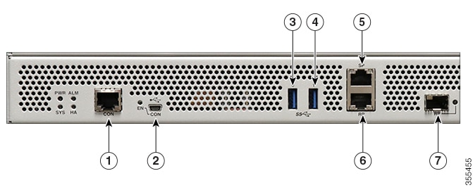
The following figure shows the management and storage connections for the Cisco Catalyst 9800-40 Wireless Controller:

|
1 |
CON—RJ-45 compatible console port |
5 |
SP—RJ-45 10/100/1000 management Ethernet port |
|
2 |
CON—Mini USB connector console port |
6 |
RP—RJ-45 10/100/1000 redundancy Ethernet port |
|
3 |
USB port 0 |
7 |
RP—1-GE SFP+ port |
|
4 |
USB port 1 |
LEDs
The following figure shows the LEDs on the front panel of the Cisco Catalyst 9800-40 Wireless Controller:

|
No. |
LED Label |
Description |
LED Color |
Behavior |
|---|---|---|---|---|
|
1 |
PWR |
Power |
Green 
|
If all the power rails are based on the specification. |
|
2 |
SYS |
System |
On 
|
Remains ON during IOS boot complete. |
|
Blinking Green 
|
Remains blinking when IOS booting is in progress. |
|||
|
Amber 
|
Remains ON during system crash. |
|||
|
Blinking Amber 
|
Remains blinking during secure boot failure. |
|||
|
Off |
Remains OFF during ROMMON boot. |
|||
|
3 |
ALM |
Alarm |
Green 
|
Remains ON during ROMMON boot complete. |
|
Blinking Green 
|
Remains blinking when system upgrade is in progress. |
|||
|
Amber 
|
Remains ON during ROMMON and SYSTEM boot ups. |
|||
|
Blinking Amber 
|
Remains blinking during temperature error and secure boot failure. |
|||
|
Red |
Indicates that the system detects critical warnings.
|
|||
|
Off |
Remains OFF during IOS boot. Normal Operation |
|||
|
4 |
HA |
High Availability |
Green 
|
Remains ON when HA is active. |
|
Blinking Green 
|
Remains blinking when HA Standby Hot. |
|||
|
Amber 
|
Blinks slowly when booted or HA Standby Cold. |
|||
|
Blinks Fast 
|
Blinks fast during HA maintenance. |
|||
|
5 |
EN |
USB console enabled |
Green 
|
Indicates that the mini USB connector is used as the console. |
|
6 |
LINK |
Management |
Solid Green 
|
Indicates that the RJ-45 connector is not used as the console. |
|
Flash Green 
|
Indicates that the RJ-45 connector is being used as the console. |
|||
|
Built-in EPA (1 SFP + Port Status of 4 LEDs with 1 per SFP) |
Off |
No link. |
||
|
Built-in EPA (1 SFP + Port Status of 4 LEDs with 1 per SFP) |
Off |
Indicates that the port is not enabled. |
||
|
Amber 
|
Port enabled with a problem in the Ethernet link. |
|||
|
Green 
|
Port enabled with a valid Ethernet link. |
|||
|
7 |
SSD |
SSD Activity |
Green 
|
Remains ON during the SSD activity. |
Rear View
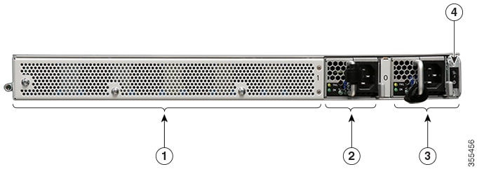
The following figure shows the rear of the Cisco Catalyst 9800-40 Wireless Controller:

|
1 |
Fans |
3 |
Power supply (PEM 0) |
|
2 |
Power supply (PEM 1) |
4 |
Power/standby switch |
The chassis has a front-to-rear airflow. Six internal fans draw cooling air into the chassis and across internal components to maintain an acceptable operating temperature. The fans are numbered from 0 to 5, right to left.
Two power supplies (AC) are accessed from the rear of the controller and are hot-swappable.
 Caution |
The Cisco Catalyst 9800-40 Wireless Controller can support two AC power supplies. |

 Feedback