FlexConnect Wireless Branch Controller Deployment Guide
Available Languages
Table of Contents
FlexConnect Wireless Branch Controller Deployment Guide
Controllers Supporting FlexConnect Mode
Advantages of Centralizing Access Point Control Traffic
Advantages of Distributing Client Data Traffic
FlexConnect Modes of Operation
Wireless Branch Network Design
Features Addressing Branch Network Design
Primary Objectives of FlexConnect Groups
Local EAP (Local Authentication Continuation)
FlexConnect Group Configuration from WLC
FlexConnect VLAN Based Central Switching
Configuration through Cisco Prime
FlexConnect Smart AP Image Upgrade
Auto Convert APs in FlexConnect Mode
FlexConnect WGB/uWGB Support for Local Switching WLANs
Support for an Increased Number of Radius Servers
Guest Access Support in FlexConnect
Support for PEAP and EAP-TLS Authentication
Certificate Generation for EAP-TLS
Configuration of EAP-TLS on FlexConnect AP
CLI Support for PEAP and EAP-TLS on FlexConnect APs
WLAN-VLAN mapping at FlexConnect Group Level
VideoStream for FlexConnect Local Switching
Supported Wireless Hardware and Software
Higher Video Scaling on Clients
Add Media Stream Configuration
Verifying VideoStream Functionality
FlexConnect Faster Time to Deploy
Features supported on Default FlexConnect Group
Features Not Supported on Default FlexConnect Group
Default FlexConnect Group with PnP
Default FlexConnect Group Web UI
Cisco Support Community - Featured Conversations
Introduction
This document describes how to deploy a Cisco FlexConnect wireless branch controller. The purpose of this document is to:
- Explain various network elements of the Cisco FlexConnect solution, along with their communication flow.
- Provide general deployment guidelines for designing the Cisco FlexConnect wireless branch solution.

Note![]() Prior to release 7.2, FlexConnect was called Hybrid REAP (HREAP). Now it is called FlexConnect.
Prior to release 7.2, FlexConnect was called Hybrid REAP (HREAP). Now it is called FlexConnect.
Prerequisites
Conventions
Refer to Cisco Technical Tips Conventions for more information on document conventions.
FlexConnect Architecture
Figure 1 Typical Wireless Branch Topology

FlexConnect is a wireless solution for branch office and remote office deployments.
The FlexConnect solution enables the customer to:
- Centralize control and manage traffic of APs from the Data Center.
- Distribute the client data traffic at each Branch Office.
–![]() Each traffic flow is going to its final destination in the most efficient manner.
Each traffic flow is going to its final destination in the most efficient manner.
Advantages of Distributing Client Data Traffic
- No operational downtime (survivability) against complete WAN link failures or controller unavailability.
- Mobility resiliency within branch during WAN link failures.
- Increase in branch scalability. Supports branch size that can scale up to 100 APs and 250,000 square feet (5000 sq. feet per AP).
The Cisco FlexConnect solution also supports Central Client Data Traffic, but it is limited to Guest data traffic only. This next table describes the restrictions on WLAN L2 security types only for non-guest clients whose data traffic is also switched centrally at the Data Center.

Note![]() These authentication restrictions do not apply to clients whose data traffic is distributed at the branch.
These authentication restrictions do not apply to clients whose data traffic is distributed at the branch.
For more information on Flexconnect external webauth deployment, please refer to Flexconnect External WebAuth Deployment Guide
For more information on HREAP/FlexConnect AP states and data traffic switching options, refer to Configuring FlexConnect.
FlexConnect Modes of Operation
For more information on FlexConnect Theory of Operations, refer to the H-Reap/FlexConnect Design and Deployment Guide.
WAN Requirements
FlexConnect APs are deployed at the Branch site and managed from the Data Center over a WAN link. The maximum transmission unit (MTU) must be at least 500 bytes.

Note![]() It is highly recommended that the minimum bandwidth restriction remains 12.8 Kbps per AP with the round trip latency no greater than 300 ms for data deployments and 100 ms for data + voice deployments.
It is highly recommended that the minimum bandwidth restriction remains 12.8 Kbps per AP with the round trip latency no greater than 300 ms for data deployments and 100 ms for data + voice deployments.
For large deployments with scale for max APs per branch = 100 and max clients per branch = 2000.
Adaptive wIPS, Context Aware (RFIDs), Rogue Detection, Clients with central 802.1X auth and CleanAir.
For 100 APs, 2000 Clients, 1000 RFIDs, 500 Rogue APs, and 2500 Rogue Clients (Features above turned on):
Recommended RTT latency = 400 ms
For 100 APs, 2000 Clients, no rogue, and no RFIDs. (Features above turned off).
Wireless Branch Network Design
The rest of this document highlights the guidelines and describes the best practices for implementing secured distributed branch networks. FlexConnect architecture is recommended for wireless branch networks that meet these design requirements.
Primary Design Requirements
- Branch size that can scale up to 100 APs and 250,000 square feet (5000 sq. feet per AP)
- Central management and troubleshooting
- No operational downtime
- Client-based traffic segmentation
- Seamless and secured wireless connectivity to corporate resources
- PCI compliant
- Support for guests
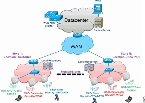
Figure 2 Wireless Branch Network Design
Overview
Branch customers find it increasingly difficult and expensive to deliver full-featured scalable and secure network services across geographic locations. In order to support customers, Cisco is addressing these challenges by introducing the FlexConnect deployment mode.
The FlexConnect solution virtualizes the complex security, management, configuration, and troubleshooting operations within the data center and then transparently extends those services to each branch. Deployments using FlexConnect are easier for IT to set up, manage and, most importantly, scale.
Features Addressing Branch Network Design
The rest of the sections in the guide captures feature usage and recommendations to realize the network design shown in Figure 2.

Note![]() Flexconnect APs implemented with WIPS mode can increase bandwidth utilization significantly based on the activity being detected by the APs. If the rules have forensics enabled, the link utilization can go up by almost 100 Kbps on an average.
Flexconnect APs implemented with WIPS mode can increase bandwidth utilization significantly based on the activity being detected by the APs. If the rules have forensics enabled, the link utilization can go up by almost 100 Kbps on an average.
Feature Matrix
Refer to FlexConnect Feature Matrix for a feature matrix for the FlexConnect feature.
AP Groups
After creating WLANs on the controller, you can selectively publish them (using access point groups) to different access points in order to better manage your wireless network. In a typical deployment, all users on a WLAN are mapped to a single interface on the controller. Therefore, all users associated with that WLAN are on the same subnet or VLAN. However, you can choose to distribute the load among several interfaces or to a group of users based on specific criteria such as individual departments (such as Marketing, Engineering or Operations) by creating access point groups. Additionally, these access point groups can be configured in separate VLANs to simplify network administration.
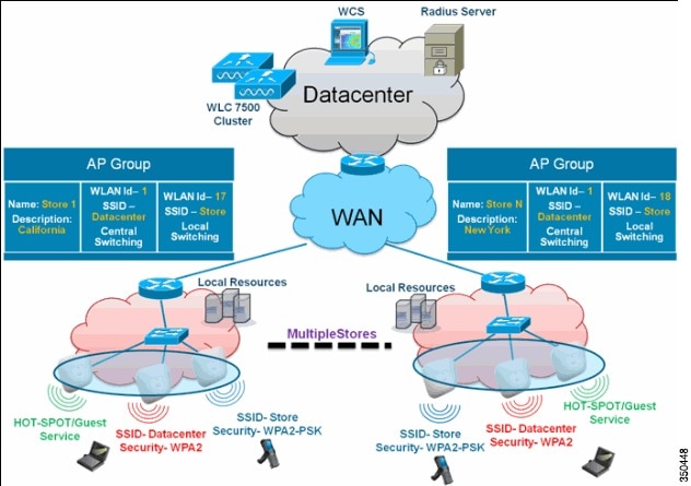
This document uses AP groups to simplify network administration when managing multiple stores across geographic locations. For operational ease, the document creates one AP-group per store to satisfy these requirements:
- Centrally Switched SSID Data center across all stores for Local Store Manager administrative access.
- Locally Switched SSID Store with different WPA2-PSK keys across all stores for hand-held scanners.
Figure 3 Wireless Network Design Reference Using AP Groups
Configurations from WLC
Step 1![]() On the WLANs > New page, enter Store1 in the Profile Name field, enter store in the SSID field, and choose 17 from the ID drop-down list.
On the WLANs > New page, enter Store1 in the Profile Name field, enter store in the SSID field, and choose 17 from the ID drop-down list.

Note![]() WLAN IDs 1-16 are part of the default group and cannot be deleted. In order to satisfy our requirement of using same SSID store per store with a different WPA2-PSK, you need to use WLAN ID 17 and beyond because these are not part of the default group and can be limited to each store.
WLAN IDs 1-16 are part of the default group and cannot be deleted. In order to satisfy our requirement of using same SSID store per store with a different WPA2-PSK, you need to use WLAN ID 17 and beyond because these are not part of the default group and can be limited to each store.

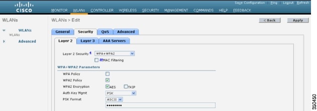
Step 2![]() Under WLAN > Security, choose PSK from the Auth Key Mgmt drop-down list, choose ASCII from the PSK Format drop-down list, and click Apply.
Under WLAN > Security, choose PSK from the Auth Key Mgmt drop-down list, choose ASCII from the PSK Format drop-down list, and click Apply.
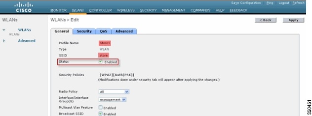
Step 3![]() Click WLAN > General, verify the Security Policies change, and check the Status box to enable the WLAN.
Click WLAN > General, verify the Security Policies change, and check the Status box to enable the WLAN.
Step 4![]() Repeat steps 1, 2 and 3 for new WLAN profile Store2, with SSID as store and ID as 18.
Repeat steps 1, 2 and 3 for new WLAN profile Store2, with SSID as store and ID as 18.


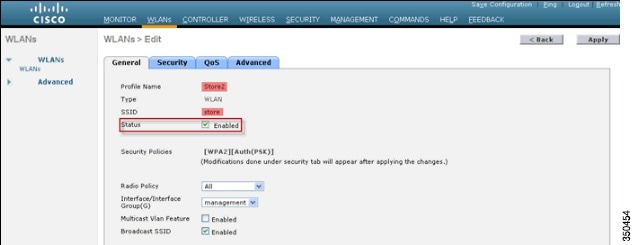
Step 5![]() Create and enable the WLAN profile with Profile Name DataCenter, SSID DataCenter and ID 1.
Create and enable the WLAN profile with Profile Name DataCenter, SSID DataCenter and ID 1.

Note![]() On creation, WLAN IDs from 1-16 are automatically part of the default-ap-group.
On creation, WLAN IDs from 1-16 are automatically part of the default-ap-group.
Step 6![]() Under WLAN, verify the status of WLAN IDs 1, 17 and 18.
Under WLAN, verify the status of WLAN IDs 1, 17 and 18.

Step 7![]() Click WLAN > Advanced > AP group > Add Group.
Click WLAN > Advanced > AP group > Add Group.
Step 8![]() Add AP Group Name as Store1, same as WLAN profile Store1, and Description as the Location of the Store. In this example, California is used as the location of the store.
Add AP Group Name as Store1, same as WLAN profile Store1, and Description as the Location of the Store. In this example, California is used as the location of the store.

Step 10![]() Click Add Group and create the AP Group Name as Store2 and the description as New York.
Click Add Group and create the AP Group Name as Store2 and the description as New York.

Step 12![]() Verify the group creation by navigating to WLAN > Advanced > AP Groups.
Verify the group creation by navigating to WLAN > Advanced > AP Groups.

Step 13![]() Click AP Group Name Store1 to add or edit the WLAN.
Click AP Group Name Store1 to add or edit the WLAN.
Step 14![]() Click Add New to select the WLAN.
Click Add New to select the WLAN.
Step 15![]() Under WLAN, from the WLAN SSID drop-down, choose WLAN ID 17 store(17).
Under WLAN, from the WLAN SSID drop-down, choose WLAN ID 17 store(17).
Step 16![]() Click Add after WLAN ID 17 is selected.
Click Add after WLAN ID 17 is selected.
Step 17![]() Repeat steps (14 -16) for WLAN ID 1 DataCenter(1). This step is optional and needed only if you want to allow Remote Resource access.
Repeat steps (14 -16) for WLAN ID 1 DataCenter(1). This step is optional and needed only if you want to allow Remote Resource access.
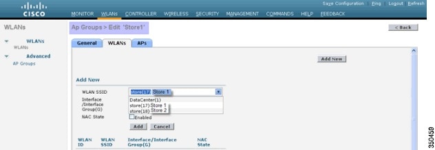
Step 18![]() Go back to the WLAN > Advanced > AP Groups screen.
Go back to the WLAN > Advanced > AP Groups screen.
Step 19![]() Click AP Group Name Store2 to add or edit WLAN.
Click AP Group Name Store2 to add or edit WLAN.
Step 20![]() Click Add New to select the WLAN.
Click Add New to select the WLAN.
Step 21![]() Under WLAN, from WLAN SSID drop-down, choose WLAN ID 18 store(18).
Under WLAN, from WLAN SSID drop-down, choose WLAN ID 18 store(18).
Step 22![]() Click Add after WLAN ID 18 is selected.
Click Add after WLAN ID 18 is selected.
Step 23![]() Repeat steps 14 -16 for WLAN ID 1 DataCenter(1).
Repeat steps 14 -16 for WLAN ID 1 DataCenter(1).
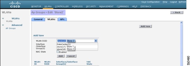

Note![]() Adding multiple WLAN profiles with the same SSID under a single AP group is not permitted.
Adding multiple WLAN profiles with the same SSID under a single AP group is not permitted.


Note![]() Adding APs to the AP group is not captured in this document, but it is needed for clients to access network services.
Adding APs to the AP group is not captured in this document, but it is needed for clients to access network services.
FlexConnect Groups
In most typical branch deployments, it is easy to foresee that client 802.1X authentication takes place centrally at the Data Center. Because the above scenario is perfectly valid, it raises these concerns:
- How can wireless clients perform 802.1X authentication and access Data Center services if WLC fails?
- How can wireless clients perform 802.1X authentication if WAN link between Branch and Data Center fails?
- Is there any impact on branch mobility during WAN failures?
- Does the FlexConnect Solution provide no operational branch downtime?
FlexConnect Group is primarily designed and should be created to address these challenges. In addition, it eases organizing each branch site, because all the FlexConnect access points of each branch site are part of a single FlexConnect Group.

Note![]() FlexConnect Groups are not analogous to AP Groups.
FlexConnect Groups are not analogous to AP Groups.
Backup RADIUS Server Failover
You can configure the controller to allow a FlexConnect access point in standalone mode to perform full 802.1X authentication to a backup RADIUS server. In order to increase the resiliency of the branch, administrators can configure a primary backup RADIUS server or both a primary and secondary backup RADIUS server. These servers are used only when the FlexConnect access point is not connected to the controller.

Note![]() Backup RADIUS accounting is not supported.
Backup RADIUS accounting is not supported.
Local Authentication
Before the 7.0.98.0 code release, local authentication was supported only when FlexConnect is in Standalone Mode to ensure client connectivity is not affected during WAN link failure. With the 7.0.116.0 release, this feature is now supported even when FlexConnect access points are in Connected Mode.
Figure 4 Central Dot1X Authentication (FlexConnect APs Acting as Authenticator)
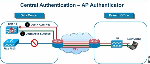
As shown in Figure 4, branch clients can continue to perform 802.1X authentication when the FlexConnect Branch APs lose connectivity with the WLC. As long as the RADIUS/ACS server is reachable from the Branch site, wireless clients will continue to authenticate and access wireless services. In other words, if the RADIUS/ACS is located inside the Branch, then clients will authenticate and access wireless services even during a WAN outage.

Note![]() With Local Authentication turned on, the AP will always authenticate the clients locally, even when it is in connected mode. When Local Authentication is disabled, the controller will authenticate clients to the Central RADIUS server when the FlexConnect AP is in connected mode. When the AP is in Standalone mode, the AP will authenticate clients to the Local RADIUS / Local EAP on AP configured on the FlexConnect Group.
With Local Authentication turned on, the AP will always authenticate the clients locally, even when it is in connected mode. When Local Authentication is disabled, the controller will authenticate clients to the Central RADIUS server when the FlexConnect AP is in connected mode. When the AP is in Standalone mode, the AP will authenticate clients to the Local RADIUS / Local EAP on AP configured on the FlexConnect Group.

Note![]() This feature can be used in conjunction with the FlexConnect backup RADIUS server feature. If a FlexConnect Group is configured with both backup RADIUS server and local authentication, the FlexConnect access point always attempts to authenticate clients using the primary backup RADIUS server first, followed by the secondary backup RADIUS server (if the primary is not reachable), and finally the Local EAP Server on FlexConnect access point itself (if the primary and secondary are not reachable).
This feature can be used in conjunction with the FlexConnect backup RADIUS server feature. If a FlexConnect Group is configured with both backup RADIUS server and local authentication, the FlexConnect access point always attempts to authenticate clients using the primary backup RADIUS server first, followed by the secondary backup RADIUS server (if the primary is not reachable), and finally the Local EAP Server on FlexConnect access point itself (if the primary and secondary are not reachable).
Local EAP (Local Authentication Continuation)
Figure 5 Dot1X Authentication (FlexConnect APs Acting as Local-EAP Server)
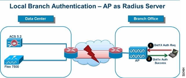
- You can configure the controller to allow a FlexConnect AP in standalone or connected mode to perform LEAP or EAP-FAST authentication for up to 100 statically configured users. The controller sends the static list of user names and passwords to each FlexConnect access point of that particular FlexConnect Group when it joins the controller. Each access point in the group authenticates only its own associated clients.
- This feature is ideal for customers who are migrating from an autonomous access point network to a lightweight FlexConnect access point network and are not interested in maintaining a large user database, or adding another hardware device to replace the RADIUS server functionality available in the autonomous access point.
- As shown in Figure 5, if the RADIUS/ACS server inside the Data Center is not reachable, then FlexConnect APs automatically acts as a Local-EAP Server to perform Dot1X authentication for wireless branch clients.
CCKM/OKC Fast Roaming
- FlexConnect Groups are required for CCKM/OKC fast roaming to work with FlexConnect access points. Fast roaming is achieved by caching a derivative of the master key from a full EAP authentication so that a simple and secure key exchange can occur when a wireless client roams to a different access point. This feature prevents the need to perform a full RADIUS EAP authentication as the client roams from one access point to another. The FlexConnect access points need to obtain the CCKM/OKC cache information for all the clients that might associate so they can process it quickly instead of sending it back to the controller. If, for example, you have a controller with 300 access points and 100 clients that might associate, sending the CCKM/OKC cache for all 100 clients is not practical. If you create a FlexConnect Group comprising a limited number of access points (for example, you create a group for four access points in a remote office), the clients roam only among those four access points, and the CCKM/OKC cache is distributed among those four access points only when the clients associate to one of them.
- This feature along with Backup Radius and Local Authentication (Local-EAP) ensures no operational downtime for your branch sites.

Note![]() CCKM/OKC fast roaming among FlexConnect and non-FlexConnect access points is not supported.
CCKM/OKC fast roaming among FlexConnect and non-FlexConnect access points is not supported.
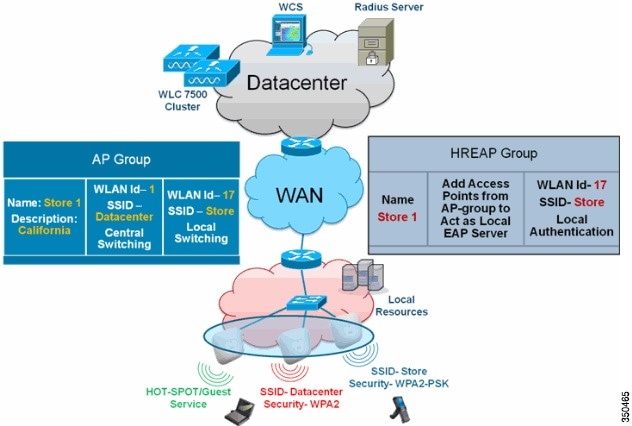
Figure 6 Wireless Network Design Reference Using FlexConnect Groups
FlexConnect Group Configuration from WLC
Complete the steps in this section in order to configure FlexConnect groups to support Local Authentication using LEAP, when FlexConnect is either in Connected or Standalone mode. The configuration sample in Figure 6 illustrates the objective differences and 1:1 mapping between the AP Group and FlexConnect group.
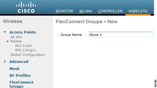
Step 1![]() Click New under Wireless > FlexConnect Groups.
Click New under Wireless > FlexConnect Groups.
Step 2![]() Assign Group Name Store 1, similar to the sample configuration as shown in Figure 6.
Assign Group Name Store 1, similar to the sample configuration as shown in Figure 6.
Step 3![]() Click Apply when the Group Name is set.
Click Apply when the Group Name is set.
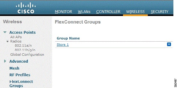
Step 4![]() Click the Group Name Store 1 that you just created for further configuration.
Click the Group Name Store 1 that you just created for further configuration.

Step 6![]() Check the Enable AP Local Authentication box in order to enable Local Authentication when the AP is in Standalone Mode.
Check the Enable AP Local Authentication box in order to enable Local Authentication when the AP is in Standalone Mode.

Note![]() Step 20 shows how to enable Local Authentication for Connected Mode AP.
Step 20 shows how to enable Local Authentication for Connected Mode AP.
Step 7![]() Check the Select APs from current controller box in order to enable the AP Name drop-down menu.
Check the Select APs from current controller box in order to enable the AP Name drop-down menu.
Step 8![]() Choose the AP from the drop-down that needs to be part of this FlexConnect Group.
Choose the AP from the drop-down that needs to be part of this FlexConnect Group.
Step 9![]() Click Add after the AP is chosen from the drop-down.
Click Add after the AP is chosen from the drop-down.
Step 10![]() Repeat steps 7 and 8 to add all the APs to this FlexConnect group that are also part of AP-Group Store 1. See Figure 6 to understand the 1:1 mapping between the AP-Group and FlexConnect group.
Repeat steps 7 and 8 to add all the APs to this FlexConnect group that are also part of AP-Group Store 1. See Figure 6 to understand the 1:1 mapping between the AP-Group and FlexConnect group.
If you have created an AP-Group per Store (Figure 3), then ideally all the APs of that AP-Group should be part of this FlexConnect Group (Figure 6. Maintaining 1:1 ratio between the AP-Group and FlexConnect group simplifies network management.

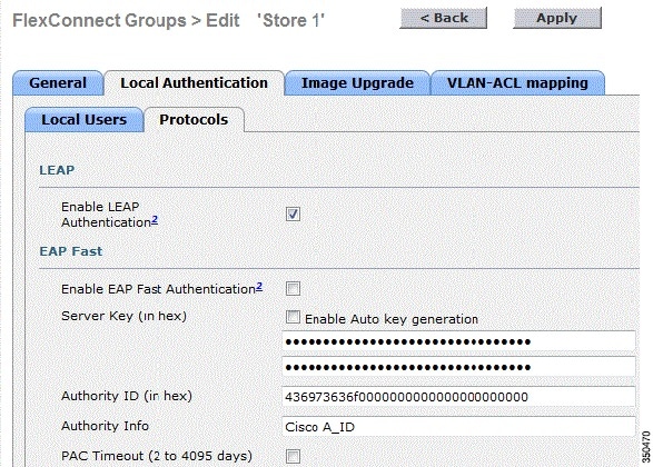
Step 11![]() Click Local Authentication > Protocols and check the Enable LEAP Authentication box.
Click Local Authentication > Protocols and check the Enable LEAP Authentication box.
Step 12![]() Click Apply after the check box is set.
Click Apply after the check box is set.

Note![]() If you have a backup controller, make sure the FlexConnect groups are identical and AP MAC address entries are included per FlexConnect group.
If you have a backup controller, make sure the FlexConnect groups are identical and AP MAC address entries are included per FlexConnect group.
Step 13![]() Under Local Authentication, click Local Users.
Under Local Authentication, click Local Users.
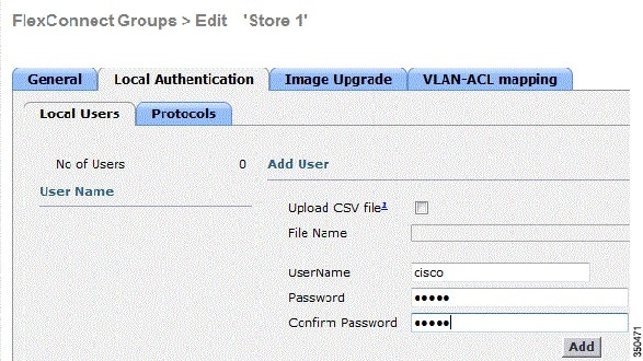
Step 14![]() Set the UserName, Password and Confirm Password fields, then click Add in order to create user entry in the Local EAP server residing on the AP.
Set the UserName, Password and Confirm Password fields, then click Add in order to create user entry in the Local EAP server residing on the AP.
Step 15![]() Repeat step 13 until your local user name list is exhausted. You cannot configure or add more than 100 users.
Repeat step 13 until your local user name list is exhausted. You cannot configure or add more than 100 users.
Step 16![]() Click Apply after step 14 is completed and the No of Users count is verified.
Click Apply after step 14 is completed and the No of Users count is verified.
Step 17![]() From the top pane, click WLANs.
From the top pane, click WLANs.
Step 18![]() Click WLAN ID 17. This was created during the AP Group creation. See Figure 3.
Click WLAN ID 17. This was created during the AP Group creation. See Figure 3.

Step 19![]() Under WLAN > Edit for WLAN ID 17, click Advanced.
Under WLAN > Edit for WLAN ID 17, click Advanced.
Step 20![]() Check the FlexConnect Local Auth box in order to enable Local Authentication in Connected Mode.
Check the FlexConnect Local Auth box in order to enable Local Authentication in Connected Mode.

Note![]() Local Authentication is supported only for FlexConnect with Local Switching.
Local Authentication is supported only for FlexConnect with Local Switching.

Note![]() Always make sure to create the FlexConnect Group before enabling Local Authentication under WLAN.
Always make sure to create the FlexConnect Group before enabling Local Authentication under WLAN.

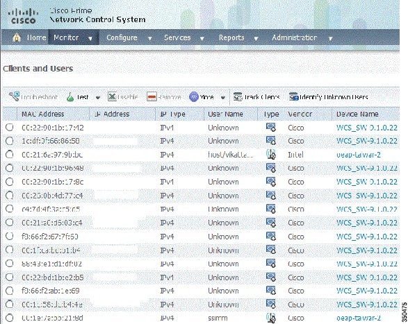
NCS and Cisco Prime also provides the FlexConnect Local Auth check box in order to enable Local Authentication in Connected Mode as shown here:

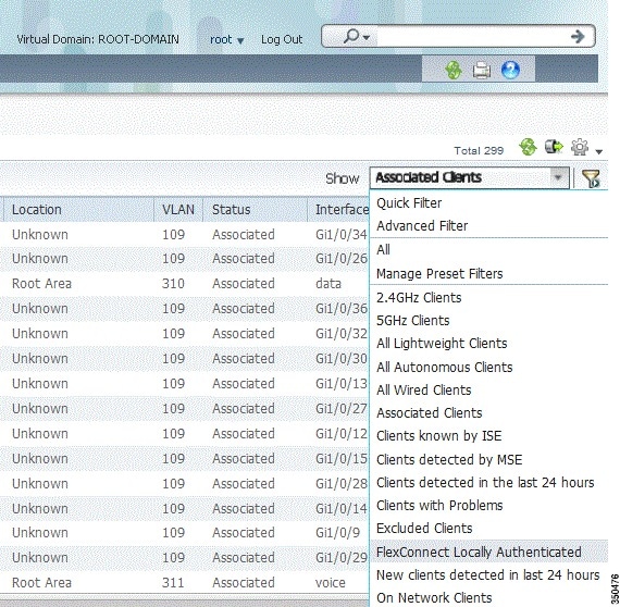
NCS and Cisco Prime also provides facility to filter and monitor FlexConnect Locally Authenticated clients as shown here:
Verification Using CLI
Client authentication state and switching mode can quickly be verified using this CLI on the WLC:
(Cisco Controller) >show client detail 00:24:d7:2b:7c:0c
Client MAC Address............................... 00:24:d7:2b:7c:0c
Client Username................................. N/A
AP MAC Address................................... d0:57:4c:08:e6:70
Client State..................................... Associated
FlexConnect VLAN Override
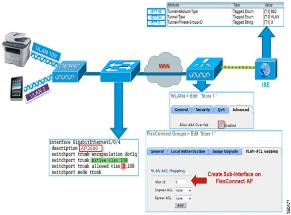
In the current FlexConnect architecture, there is a strict mapping of WLAN to VLAN, and thus the client getting associated on a particular WLAN on FlexConnect AP has to abide by a VLAN which is mapped to it. This method has limitations, because it requires clients to associate with different SSIDs in order to inherit different VLAN-based policies.
From 7.2 release onwards, AAA override of VLAN on individual WLAN configured for local switching is supported. In order to have dynamic VLAN assignment, AP would have the interfaces for the VLAN pre-created based on a configuration using existing WLAN-VLAN Mapping for individual FlexConnect AP or using ACL-VLAN mapping on a FlexConnect group. The WLC is used to pre-create the sub-interfaces at the AP.
Summary
- AAA VLAN override is supported from release 7.2 for WLANs configured for local switching in central and local authentication mode.
- AAA override should be enabled on WLAN configured for local switching.
- The FlexConnect AP should have VLAN pre-created from WLC for dynamic VLAN assignment.
- If VLANs returned by AAA override are not present on AP client, they will get an IP from the default VLAN interface of the AP.
Procedure
Step 1![]() Create a WLAN for 802.1x authentication.
Create a WLAN for 802.1x authentication.

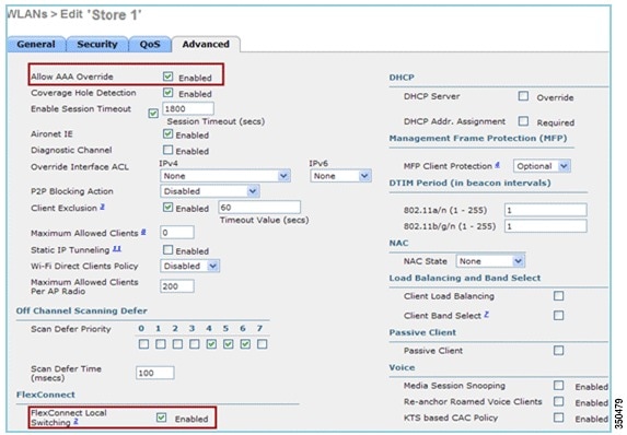
Step 2![]() Enable AAA override support for local switching WLAN on the WLC. Navigate to WLAN GUI > WLAN > WLAN ID > Advance tab.
Enable AAA override support for local switching WLAN on the WLC. Navigate to WLAN GUI > WLAN > WLAN ID > Advance tab.
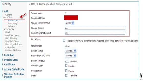
Step 3![]() Add the AAA server details on the controller for 802.1x authentication. In order to add the AAA server, navigate to WLC GUI > Security > AAA > Radius > Authentication > New.
Add the AAA server details on the controller for 802.1x authentication. In order to add the AAA server, navigate to WLC GUI > Security > AAA > Radius > Authentication > New.
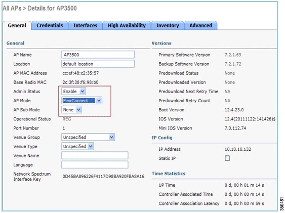
Step 4![]() The AP is in local mode by default, so covert the mode to FlexConnect mode. Local mode APs can be converted to FlexConnect mode by going to Wireless > All APs, and click the Individual AP.
The AP is in local mode by default, so covert the mode to FlexConnect mode. Local mode APs can be converted to FlexConnect mode by going to Wireless > All APs, and click the Individual AP.
Step 5![]() Add the FlexConnect APs to the FlexConnect group.
Add the FlexConnect APs to the FlexConnect group.
Navigate under WLC GUI > Wireless > FlexConnect Groups > Select FlexConnect Group > General tab > Add AP.
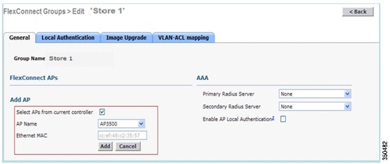
Step 6![]() The FlexConnect AP should be connected on a trunk port and WLAN mapped VLAN and AAA overridden VLAN should be allowed on the trunk port.
The FlexConnect AP should be connected on a trunk port and WLAN mapped VLAN and AAA overridden VLAN should be allowed on the trunk port.
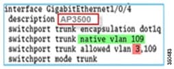

Note![]() In this configuration, VLAN 109 is used for WLAN VLAN mapping and VLAN 3 is used for AAA override.
In this configuration, VLAN 109 is used for WLAN VLAN mapping and VLAN 3 is used for AAA override.
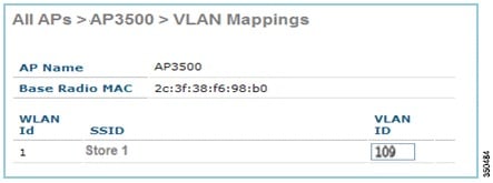
Step 7![]() Configure WLAN to VLAN Mapping for the FlexConnect AP. Based on this configuration, the AP would have the interfaces for the VLAN. When the AP receives the VLAN configuration, corresponding dot11 and Ethernet sub-interfaces are created and added to a bridge-group. Associate a client on this WLAN and when the client associates, its VLAN (default, based on the WLAN-VLAN mapping) is assigned.
Configure WLAN to VLAN Mapping for the FlexConnect AP. Based on this configuration, the AP would have the interfaces for the VLAN. When the AP receives the VLAN configuration, corresponding dot11 and Ethernet sub-interfaces are created and added to a bridge-group. Associate a client on this WLAN and when the client associates, its VLAN (default, based on the WLAN-VLAN mapping) is assigned.
Navigate to WLAN GUI > Wireless > All APs, click the specific AP > FlexConnect tab, and click VLAN Mapping.
Step 8![]() Create a user in the AAA server and configure the user to return VLAN ID in IETF Radius attribute.
Create a user in the AAA server and configure the user to return VLAN ID in IETF Radius attribute.

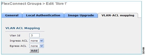
Step 9![]() In order to have dynamic VLAN assignment, the AP would have the interfaces for the dynamic VLAN pre-created based on the configuration using existing WLAN-VLAN Mapping for the individual FlexConnect AP or using ACL-VLAN mapping on FlexConnect group.
In order to have dynamic VLAN assignment, the AP would have the interfaces for the dynamic VLAN pre-created based on the configuration using existing WLAN-VLAN Mapping for the individual FlexConnect AP or using ACL-VLAN mapping on FlexConnect group.
In order to configure AAA VLAN on the FlexConnect AP, navigate to WLC GUI > Wireless > FlexConnect Group, click the specific FlexConnect group > VLAN-ACL mapping, and enter VLAN in the Vlan ID field.
Step 10![]() Associate a client on this WLAN and authenticate using the user name configured in the AAA server in order to return the AAA VLAN.
Associate a client on this WLAN and authenticate using the user name configured in the AAA server in order to return the AAA VLAN.
Step 11![]() The client should receive an IP address from the dynamic VLAN returned via the AAA server.
The client should receive an IP address from the dynamic VLAN returned via the AAA server.
Step 12![]() In order to verify, click WLC GUI > Monitor > Client, click the specific client MAC address in order to check the client details.
In order to verify, click WLC GUI > Monitor > Client, click the specific client MAC address in order to check the client details.
FlexConnect VLAN Based Central Switching
In controller software releases 7.2, AAA override of VLAN (Dynamic VLAN assignment) for locally switched WLANs will put wireless clients to the VLAN provided by the AAA server. If the VLAN provided by the AAA server is not present at the AP, the client is put to a WLAN mapped VLAN on that AP and traffic will switch locally on that VLAN. Further, prior to release 7.3, traffic for a particular WLAN from FlexConnect APs can be switched Centrally or Locally depending on the WLAN configuration.
From release 7.3 onwards, traffic from FlexConnect APs can be switched Centrally or Locally depending on the presence of a VLAN on a FlexConnect AP.

Summary
Traffic flow on WLANs configured for Local Switching when Flex APs are in Connected Mode:
- If the VLAN is returned as one of the AAA attributes and that VLAN is not present in the Flex AP database, traffic will switch centrally and the client will be assigned this VLAN/Interface returned from the AAA server provided that the VLAN exists on the WLC.
- If the VLAN is returned as one of the AAA attributes and that VLAN is not present in the Flex AP database, traffic will switch centrally. If that VLAN is also not present on the WLC, the client will be assigned a VLAN/Interface mapped to a WLAN on the WLC.
- If the VLAN is returned as one of the AAA attributes and that VLAN is present in the FlexConnect AP database, traffic will switch locally.
- If the VLAN is not returned from the AAA server, the client will be assigned a WLAN mapped VLAN on that FlexConnect AP and traffic will switch locally.
Traffic flow on WLANs configured for Local Switching when Flex APs are in Standalone Mode:
- If the VLAN returned by an AAA server is not present in the Flex AP database, the client will be put to default VLAN (that is, a WLAN mapped VLAN on Flex AP). When the AP connects back, this client will be de-authenticated and will switch traffic centrally.
- If the VLAN returned by an AAA server is present in the Flex AP database, the client will be put into a returned VLAN and traffic will switch locally.
- If the VLAN is not returned from an AAA server, the client will be assigned a WLAN mapped VLAN on that FlexConnect AP and traffic will switch locally.
Procedure
Step 1![]() Configure a WLAN for Local Switching and enable AAA override.
Configure a WLAN for Local Switching and enable AAA override.
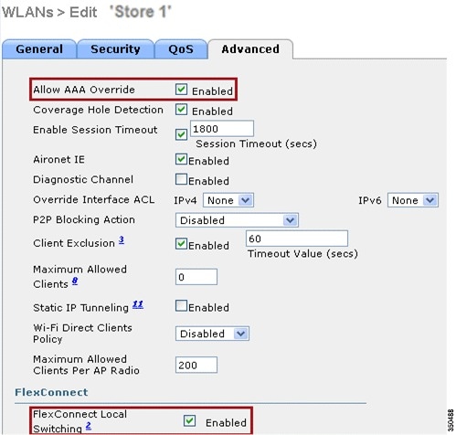
Step 2![]() Enable Vlan based Central Switching on the newly created WLAN.
Enable Vlan based Central Switching on the newly created WLAN.

Step 3![]() Set AP Mode to FlexConnect.
Set AP Mode to FlexConnect.
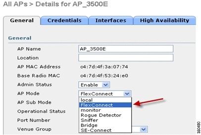
Step 4![]() Make sure that the FlexConnect AP has some sub-interface present in its database, either via WLAN-VLAN Mapping on a particular Flex AP or via configuring VLAN from a Flex group. In this example, VLAN 63 is configured in WLAN-VLAN mapping on Flex AP.
Make sure that the FlexConnect AP has some sub-interface present in its database, either via WLAN-VLAN Mapping on a particular Flex AP or via configuring VLAN from a Flex group. In this example, VLAN 63 is configured in WLAN-VLAN mapping on Flex AP.
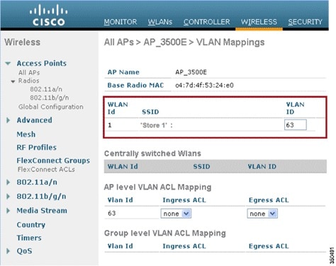
Step 5![]() In this example, VLAN 62 is configured on WLC as one of the dynamic interfaces and is not mapped to the WLAN on the WLC. The WLAN on the WLC is mapped to Management VLAN (that is, VLAN 61).
In this example, VLAN 62 is configured on WLC as one of the dynamic interfaces and is not mapped to the WLAN on the WLC. The WLAN on the WLC is mapped to Management VLAN (that is, VLAN 61).

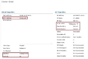
Step 6![]() Associate a client to the WLAN configured in Step 1 on this Flex AP and return VLAN 62 from the AAA server. VLAN 62 is not present on this Flex AP, but it is present on the WLC as a dynamic interface so traffic will switch centrally and the client will be assigned VLAN 62 on the WLC. In the output captured here, the client has been assigned VLAN 62 and Data Switching and Authentication are set to Central.
Associate a client to the WLAN configured in Step 1 on this Flex AP and return VLAN 62 from the AAA server. VLAN 62 is not present on this Flex AP, but it is present on the WLC as a dynamic interface so traffic will switch centrally and the client will be assigned VLAN 62 on the WLC. In the output captured here, the client has been assigned VLAN 62 and Data Switching and Authentication are set to Central.


Note![]() Observe that although WLAN is configured for Local Switching, the Data Switching field for this client is Central based on the presence of a VLAN (that is, VLAN 62, which is returned from the AAA server, is not present in the AP Database).
Observe that although WLAN is configured for Local Switching, the Data Switching field for this client is Central based on the presence of a VLAN (that is, VLAN 62, which is returned from the AAA server, is not present in the AP Database).
Step 7![]() If another user associates to the same AP on this created WLAN and some VLAN is returned from the AAA server which is not present on the AP as well as the WLC, traffic will switch centrally and the client will be assigned the WLAN mapped interface on the WLC (that is, VLAN 61 in this example setup), because the WLAN is mapped to the Management interface which is configured for VLAN 61.
If another user associates to the same AP on this created WLAN and some VLAN is returned from the AAA server which is not present on the AP as well as the WLC, traffic will switch centrally and the client will be assigned the WLAN mapped interface on the WLC (that is, VLAN 61 in this example setup), because the WLAN is mapped to the Management interface which is configured for VLAN 61.
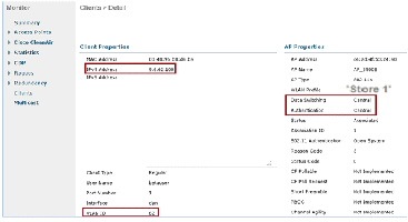

Note![]() Observe that although WLAN is configured for Local Switching, the Data Switching field for this client is Central based on the presence of a VLAN. That is, VLAN 61, which is returned from the AAA server, is not present in the AP Database but is also not present in the WLC database. As a result, the client is assigned a default interface VLAN/Interface which is mapped to the WLAN. In this example, the WLAN is mapped to a management interface (that is, VLAN 61) and so the client has received an IP address from VLAN 61.
Observe that although WLAN is configured for Local Switching, the Data Switching field for this client is Central based on the presence of a VLAN. That is, VLAN 61, which is returned from the AAA server, is not present in the AP Database but is also not present in the WLC database. As a result, the client is assigned a default interface VLAN/Interface which is mapped to the WLAN. In this example, the WLAN is mapped to a management interface (that is, VLAN 61) and so the client has received an IP address from VLAN 61.
Step 8![]() If another user associates to it on this created WLAN and VLAN 63 is returned from the AAA server (which is present on this Flex AP), the client will be assigned VLAN 63 and traffic will switch locally.
If another user associates to it on this created WLAN and VLAN 63 is returned from the AAA server (which is present on this Flex AP), the client will be assigned VLAN 63 and traffic will switch locally.
FlexConnect ACL
With the introduction of ACLs on FlexConnect, there is a mechanism to cater to the need of access control at the FlexConnect AP for protection and integrity of locally switched data traffic from the AP. FlexConnect ACLs are created on the WLC and should then be configured with the VLAN present on the FlexConnect AP or FlexConnect group using VLAN-ACL mapping which will be for AAA override VLANs. These are then pushed to the AP.

Summary
- Create FlexConnect ACL on the controller.
- Apply the same on a VLAN present on FlexConnect AP under AP Level VLAN ACL mapping.
- Can be applied on a VLAN present in FlexConnect Group under VLAN-ACL mapping (generally done for AAA overridden VLANs).
- While applying ACL on VLAN, select the direction to be applied which will be “ingress”, “egress” or “ingress and egress”.
Procedure
Step 1![]() Create a FlexConnect ACL on the WLC. Navigate to WLC GUI > Security > Access Control List > FlexConnect ACLs.
Create a FlexConnect ACL on the WLC. Navigate to WLC GUI > Security > Access Control List > FlexConnect ACLs.

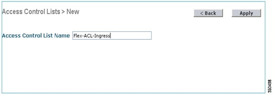
Step 3![]() Configure the ACL Name.
Configure the ACL Name.
Step 5![]() Create rules for each ACL. In order to create rules, navigate to WLC GUI > Security > Access Control List > FlexConnect ACLs, and click the above created ACL.
Create rules for each ACL. In order to create rules, navigate to WLC GUI > Security > Access Control List > FlexConnect ACLs, and click the above created ACL.

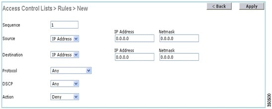

Note![]() Configure the rules as per the requirement. If the permit any rule is not configured at the end, there is an implicit deny which will block all traffic.
Configure the rules as per the requirement. If the permit any rule is not configured at the end, there is an implicit deny which will block all traffic.
Step 7![]() Once the FlexConnect ACLs are created, it can be mapped for WLAN-VLAN mapping under individual FlexConnect AP or can be applied on VLAN-ACL mapping on the FlexConnect group.
Once the FlexConnect ACLs are created, it can be mapped for WLAN-VLAN mapping under individual FlexConnect AP or can be applied on VLAN-ACL mapping on the FlexConnect group.
Step 8![]() Map FlexConnect ACL configured above at AP level for individual VLANs under VLAN mappings for individual FlexConnect AP. Navigate to WLC GUI > Wireless > All AP, click the specific AP > FlexConnect tab > VLAN Mapping.
Map FlexConnect ACL configured above at AP level for individual VLANs under VLAN mappings for individual FlexConnect AP. Navigate to WLC GUI > Wireless > All AP, click the specific AP > FlexConnect tab > VLAN Mapping.
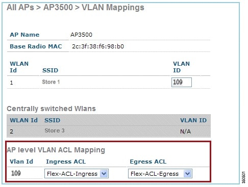
Step 9![]() FlexConnect ACL can also be applied on VLAN-ACL mapping in the FlexConnect group. VLANs created under VLAN-ACL mapping in FlexConnect group are mainly used for dynamic VLAN override.
FlexConnect ACL can also be applied on VLAN-ACL mapping in the FlexConnect group. VLANs created under VLAN-ACL mapping in FlexConnect group are mainly used for dynamic VLAN override.

FlexConnect Split Tunneling
In WLC releases prior to 7.3, if a client connecting on a FlexConnect AP associated with a centrally switched WLAN needs to send some traffic to a device present in the local site/network, they need to send traffic over CAPWAP to the WLC and then get the same traffic back to the local site over CAPWAP or using some off-band connectivity.
From release 7.3 onwards, Split Tunneling introduces a mechanism by which the traffic sent by the client will be classified based on packet contents using Flex ACL. Matching packets are switched locally from Flex AP and the rest of the packets are centrally switched over CAPWAP.
The Split Tunneling functionality is an added advantage for OEAP AP setup where clients on a Corporate SSID can talk to devices on a local network (printers, wired machine on a Remote LAN Port, or wireless devices on a Personal SSID) directly without consuming WAN bandwidth by sending packets over CAPWAP. Split tunneling is not supported on OEAP 600 APs. Flex ACL can be created with rules in order to permit all the devices present at the local site/network. When packets from a wireless client on the Corporate SSID matches the rules in Flex ACL configured on OEAP AP, that traffic is switched locally and the rest of the traffic (that is, implicit deny traffic) will switch centrally over CAPWAP.
The Split Tunneling solution assumes that the subnet/VLAN associated with a client in the central site is not present in the local site (that is, traffic for clients which receive an IP address from the subnet present on the central site will not be able to switch locally). The Split Tunneling functionality is designed to switch traffic locally for subnets which belong to the local site in order to avoid WAN bandwidth consumption. Traffic which matches the Flex ACL rules are switched locally and NAT operation is performed changing the client’s source IP address to the Flex AP’s BVI interface IP address which is routable at the local site/network.

Summary
- The Split Tunneling functionality is supported on WLANs configured for Central Switching advertised by Flex APs only.
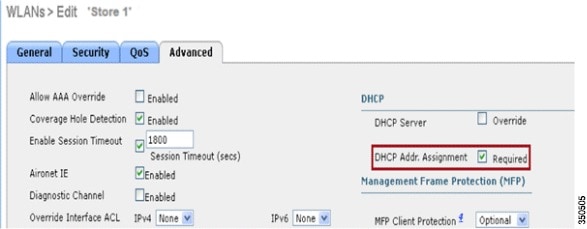
- The DHCP required should be enabled on WLANs configured for Split Tunneling.
- The Split Tunneling configuration is applied per WLAN configured for central switching on per Flex AP or for all the Flex APs in a FlexConnect Group.
Procedure
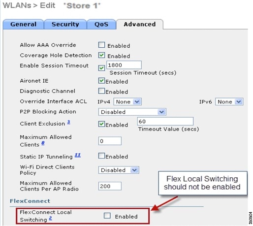
Step 1![]() Configure a WLAN for Central Switching (that is, Flex Local Switching should not be enabled).
Configure a WLAN for Central Switching (that is, Flex Local Switching should not be enabled).
Step 2![]() Set DHCP Address Assignment to Required.
Set DHCP Address Assignment to Required.
Step 3![]() Set AP Mode to FlexConnect.
Set AP Mode to FlexConnect.

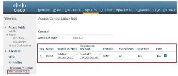
Step 4![]() Configure FlexConnect ACL with a permit rule for traffic which should be switched locally on the Central Switch WLAN. In this example, the FlexConnect ACL rule is configured so it will alert ICMP traffic from all the clients which are on the 9.6.61.0 subnet (that is, exist on the Central site) to 9.1.0.150 to be switched locally after the NAT operation is applied on Flex AP. The rest of the traffic will hit an implicit deny rule and be switched centrally over CAPWAP.
Configure FlexConnect ACL with a permit rule for traffic which should be switched locally on the Central Switch WLAN. In this example, the FlexConnect ACL rule is configured so it will alert ICMP traffic from all the clients which are on the 9.6.61.0 subnet (that is, exist on the Central site) to 9.1.0.150 to be switched locally after the NAT operation is applied on Flex AP. The rest of the traffic will hit an implicit deny rule and be switched centrally over CAPWAP.
Step 5![]() This created FlexConnect ACL can be pushed as a Split Tunnel ACL to individual Flex AP or can also be pushed to all the Flex APs in a Flex Connect group.
This created FlexConnect ACL can be pushed as a Split Tunnel ACL to individual Flex AP or can also be pushed to all the Flex APs in a Flex Connect group.
Complete these steps in order to push Flex ACL as a Local Split ACL to individual Flex AP:
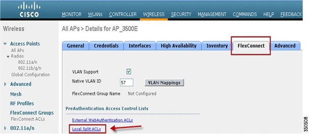
b.![]() Select WLAN Id on which Split Tunnel feature should be enabled, choose Flex-ACL, and click Add.
Select WLAN Id on which Split Tunnel feature should be enabled, choose Flex-ACL, and click Add.

c.![]() Flex-ACL is pushed as Local-Split ACL to the Flex AP.
Flex-ACL is pushed as Local-Split ACL to the Flex AP.
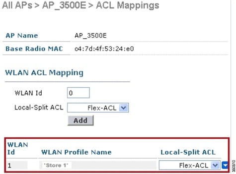
Complete these steps in order to push Flex ACL as Local Split ACL to a FlexConnect Group:
a.![]() Select the WLAN Id on which the Split Tunneling feature should be enabled. On the WLAN-ACL mapping tab, select FlexConnect ACL from the FlexConnect group where particular Flex APs are added, and click Add.
Select the WLAN Id on which the Split Tunneling feature should be enabled. On the WLAN-ACL mapping tab, select FlexConnect ACL from the FlexConnect group where particular Flex APs are added, and click Add.

b.![]() The Flex-ACL is pushed as LocalSplit ACL to Flex APs in that Flex group.
The Flex-ACL is pushed as LocalSplit ACL to Flex APs in that Flex group.

Limitations
- Flex ACL rules should not be configured with permit/deny statement with same subnet as source and destination.
- Traffic on a Centrally Switched WLAN configured for Split Tunneling can be switched locally only when a wireless client initiates traffic for a host present on the local site. If traffic is initiated by clients/host on a local site for wireless clients on these configured WLANs, it will not be able to reach the destination.
- Split Tunneling is not supported for Multicast/Broadcast traffic. Multicast/Broadcast traffic will switch centrally even if it matches the Flex ACL.
Fault Tolerance
FlexConnect Fault Tolerance allows wireless access and services to branch clients when:
- FlexConnect Branch APs lose connectivity with the primary controller.
- FlexConnect Branch APs are switching to the secondary controller.
- FlexConnect Branch APs are re-establishing connection to the primary controller.
FlexConnect Fault Tolerance, along with Local EAP as outlined above and PEAP/EAP-TLS authentication on FlexConnect AP with release 7.5, together provide zero branch downtime during a network outage. This feature is enabled by default and cannot be disabled. It requires no configuration on the controller or AP. However, to ensure Fault Tolerance works smoothly and is applicable, this criteria should be maintained:
- WLAN ordering and configurations have to be identical across the primary and backup controllers.
- VLAN mapping has to be identical across the primary and backup controllers.
- Mobility domain name has to be identical across the primary and backup controllers.
Summary
- FlexConnect will not disconnect clients when the AP is connecting back to the same controller provided there is no change in configuration on the controller.
- FlexConnect will not disconnect clients when connecting to the backup controller provided there is no change in configuration and the backup controller is identical to the primary controller.
- FlexConnect will not reset its radios on connecting back to the primary controller provided there is no change in configuration on the controller.
Limitations
- Supported only for FlexConnect with Central/Local Authentication with Local Switching.
- Centrally authenticated clients require full re-authentication if the client session timer expires before the FlexConnect AP switches from Standalone to Connected mode.
- FlexConnect primary and backup controllers must be in the same mobility domain.
Client Limit per WLAN
Along with traffic segmentation, the need for restricting the total client accessing the wireless services arises. For example, limiting total Guest Clients from branch tunneling back to the Data Center.
In order to address this challenge, Cisco is introducing Client Limit per WLAN feature that can restrict the total clients allowed on a per WLAN basis.
Primary Objective

Note![]() This is not a form of QoS.
This is not a form of QoS.
By default, the feature is disabled and does not force the limit.
Limitations
This feature does not enforce client limit when the FlexConnect is in Standalone state of operation.
Any configuration mismatch across WLCs in any of below will result in radio reset at AP:
1.![]() Flexconnect group (all possible configs)
Flexconnect group (all possible configs)
2.![]() WLAN to WLAN mapping per AP / AP Group / WLAN
WLAN to WLAN mapping per AP / AP Group / WLAN
WLC Configuration
Step 1![]() Select the Centrally Switched WLAN ID 1 with SSID DataCenter. This WLAN was created during THE AP Group creation. See Figure 3.
Select the Centrally Switched WLAN ID 1 with SSID DataCenter. This WLAN was created during THE AP Group creation. See Figure 3.
Step 2![]() Click the Advanced tab for WLAN ID 1.
Click the Advanced tab for WLAN ID 1.
Step 3![]() Set the client limit value for the Maximum Allowed Clients text field.
Set the client limit value for the Maximum Allowed Clients text field.
Step 4![]() Click Apply after the text field for Maximum Allowed Clients is set.
Click Apply after the text field for Maximum Allowed Clients is set.
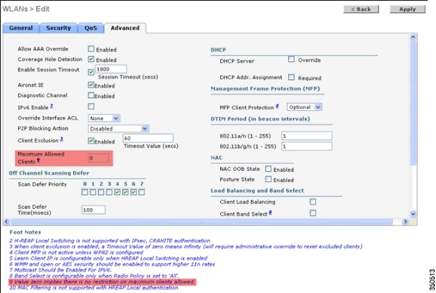
Default for Maximum Allowed Clients is set to 0, which implies there is no restriction and the feature is disabled.
Peer-to-Peer Blocking
In controller software releases prior to 7.2, peer-to-peer (P2P) blocking was only supported for central switching WLANs. Peer-to-peer blocking can be configured on WLAN with any of these three actions:
- Disabled – Disables peer-to-peer blocking and bridged traffic locally within the controller for clients in the same subnet. This is the default value.
- Drop – Causes the controller to discard packets for clients in the same subnet.
- Forward Up-Stream – Causes the packet to be forwarded on the upstream VLAN. The devices above the controller decide what action to take regarding the packet.
From release 7.2 onwards, peer-to-peer blocking is supported for clients associated on local switching WLAN. Per WLAN, peer-to-peer configuration is pushed by the controller to FlexConnect AP.

Procedure
Step 1![]() Enable peer-to-peer blocking action as Drop on WLAN configured for FlexConnect Local Switching.
Enable peer-to-peer blocking action as Drop on WLAN configured for FlexConnect Local Switching.
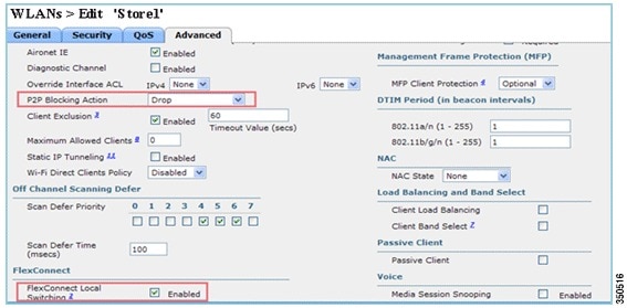
Step 2![]() Once the P2P Blocking action is configured as Drop or Forward-Upstream on WLAN configured for local switching, it is pushed from the WLC to the FlexConnect AP. The FlexConnect APs will store this information in the reap config file in flash. With this, even when FlexConnect AP is in standalone mode, it can apply the P2P configuration on the corresponding sub-interfaces.
Once the P2P Blocking action is configured as Drop or Forward-Upstream on WLAN configured for local switching, it is pushed from the WLC to the FlexConnect AP. The FlexConnect APs will store this information in the reap config file in flash. With this, even when FlexConnect AP is in standalone mode, it can apply the P2P configuration on the corresponding sub-interfaces.
Limitations
- In FlexConnect, solution P2P blocking configuration cannot be applied only to a particular FlexConnect AP or sub-set of APs. It is applied to all FlexConnect APs that broadcast the SSID.
- Unified solution for central switching clients supports P2P upstream-forward. However, this will not be supported in the FlexConnect solution. This is treated as P2P drop and client packets are dropped instead of forwarded to the next network node.
- Unified solution for central switching clients supports P2P blocking for clients associated to different APs. However, this solution targets only clients connected to the same AP. FlexConnect ACLs can be used as a workaround for this limitation.
AP Pre-Image Download
This feature allows the AP to download code while it is operational. The AP pre-image download is extremely useful in reducing the network downtime during software maintenance or upgrades.
Procedure
Step 1![]() Upgrade the image on the primary and backup controllers.
Upgrade the image on the primary and backup controllers.
Navigate under WLC GUI > Commands > Download File to start the download.
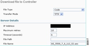
Step 2![]() Save the configurations on the controllers, but do not reboot the controller.
Save the configurations on the controllers, but do not reboot the controller.
Step 3![]() Issue the AP pre-image download command from the primary controller.
Issue the AP pre-image download command from the primary controller.
a.![]() Navigate to WLC GUI > Wireless > Access Points > All APs and choose the access point to start pre-image download.
Navigate to WLC GUI > Wireless > Access Points > All APs and choose the access point to start pre-image download.
b.![]() Once the access point is chosen, click the Advanced tab.
Once the access point is chosen, click the Advanced tab.
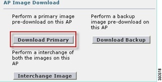
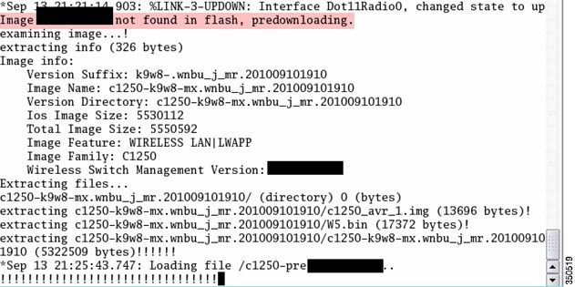
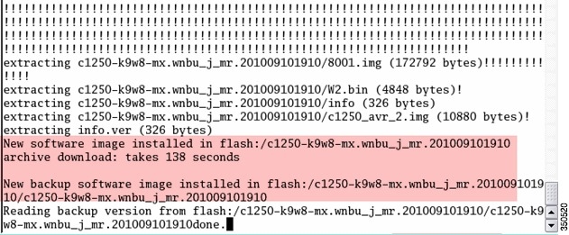
c.![]() Click Download Primary to initiate pre-image download.
Click Download Primary to initiate pre-image download.
Step 4![]() Reboot the controllers after all the AP images are downloaded.
Reboot the controllers after all the AP images are downloaded.
The APs now fall back to Standalone mode until the controllers are rebooting.

Note![]() In Standalone mode, Fault Tolerance will keep Clients associated.
In Standalone mode, Fault Tolerance will keep Clients associated.
Once the controller is back, the APs automatically reboot with the pre-downloaded image. After rebooting, the APs re-join the primary controller and resume client's services.
FlexConnect Smart AP Image Upgrade
The pre-image download feature reduces the downtime duration to a certain extent, but still all the FlexConnect APs have to pre-download the respective AP images over the WAN link with higher latency.
Efficient AP Image Upgrade will reduce the downtime for each FlexConnect AP. The basic idea is only one AP of each AP model will download the image from the controller and will act as Primary/Server, and the rest of the APs of the same model will work as Secondary/Client and will pre-download the AP image from the primary. The distribution of AP image from the server to the client will be on a local network and will not experience the latency of the WAN link. As a result, the process will be faster.

Procedure
Step 1![]() Upgrade the image on the controller.
Upgrade the image on the controller.
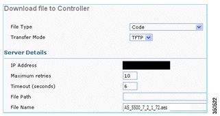
Navigate to WLC GUI > Commands > Download File in order to begin the download.
Step 2![]() Save the configurations on the controllers, but do not reboot the controller.
Save the configurations on the controllers, but do not reboot the controller.
Step 3![]() Add the FlexConnect APs to FlexConnect group.
Add the FlexConnect APs to FlexConnect group.
Navigate to WLC GUI > Wireless > FlexConnect Groups, select FlexConnect Group > General tab > Add AP.

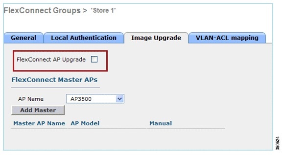
Step 4![]() Click the FlexConnect AP Upgrade check box in order to achieve efficient AP image upgrade.
Click the FlexConnect AP Upgrade check box in order to achieve efficient AP image upgrade.
Navigate to WLC GUI > Wireless > FlexConnect Groups, select FlexConnect Group > Image Upgrade tab.
Step 5![]() The Primary AP can be selected manually or automatically:
The Primary AP can be selected manually or automatically:
a.![]() In order to manually select the Primary AP, navigate to WLC GUI > Wireless > FlexConnect Groups, select FlexConnect Group > Image Upgrade tab > FlexConnect Master APs, and select AP from the drop-down list, and click Add Master.
In order to manually select the Primary AP, navigate to WLC GUI > Wireless > FlexConnect Groups, select FlexConnect Group > Image Upgrade tab > FlexConnect Master APs, and select AP from the drop-down list, and click Add Master.
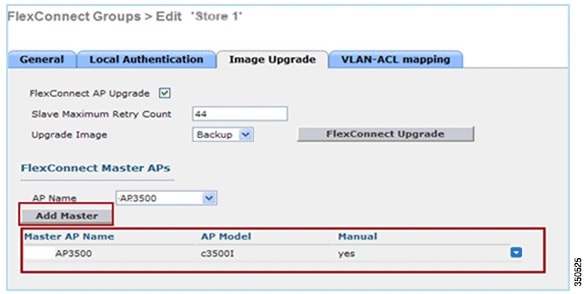

Note![]() Only one AP per model can be configured as Primary AP. If Primary AP is configured manually, the Manual field will be updated as yes.
Only one AP per model can be configured as Primary AP. If Primary AP is configured manually, the Manual field will be updated as yes.
b.![]() In order to automatically select Primary AP, navigate to WLC GUI > Wireless > FlexConnect Groups, select FlexConnect Group > Image Upgrade tab, and click FlexConnect Upgrade.
In order to automatically select Primary AP, navigate to WLC GUI > Wireless > FlexConnect Groups, select FlexConnect Group > Image Upgrade tab, and click FlexConnect Upgrade.
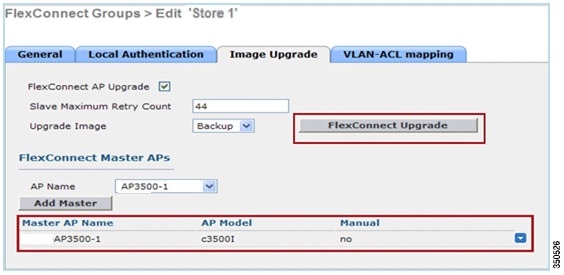

Note![]() If Primary AP is selected automatically, the Manual field will be updated as no.
If Primary AP is selected automatically, the Manual field will be updated as no.
Step 6![]() In order to start efficient AP image upgrade for all the APs under a specific FlexConnect group, click FlexConnect Upgrade.
In order to start efficient AP image upgrade for all the APs under a specific FlexConnect group, click FlexConnect Upgrade.
Navigate to WLC GUI > Wireless > FlexConnect Groups, select FlexConnect group > Image Upgrade tab and click FlexConnect Upgrade.
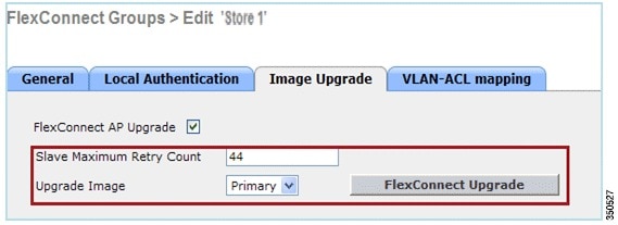

Note![]() Secondary Maximum Retry Count is the number of attempts (44 by default) in which the secondary AP will make in order to download an image from the Primary AP, after which it will fall back to download the image from the WLC. It will make 20 attempts against WLC in order to download a new image after which the administrator has to re-initiate the download process.
Secondary Maximum Retry Count is the number of attempts (44 by default) in which the secondary AP will make in order to download an image from the Primary AP, after which it will fall back to download the image from the WLC. It will make 20 attempts against WLC in order to download a new image after which the administrator has to re-initiate the download process.
Step 7![]() Once FlexConnect Upgrade is initiated, only the Primary AP will download the image from the WLC. Under All AP page, Upgrade Role will be updated as Master/Central which means Primary AP has downloaded the image from the WLC which is at the central location. The Secondary AP will download the image from the Primary AP which is at the local site and is the reason under All AP page Upgrade Role will be updated as Slave/Local.
Once FlexConnect Upgrade is initiated, only the Primary AP will download the image from the WLC. Under All AP page, Upgrade Role will be updated as Master/Central which means Primary AP has downloaded the image from the WLC which is at the central location. The Secondary AP will download the image from the Primary AP which is at the local site and is the reason under All AP page Upgrade Role will be updated as Slave/Local.
In order to verify this, navigate to WLC GUI > Wireless.

Step 8![]() Reboot the controllers after all the AP images are downloaded. The APs now fall back to Standalone mode until the controllers are rebooting.
Reboot the controllers after all the AP images are downloaded. The APs now fall back to Standalone mode until the controllers are rebooting.

Note![]() In Standalone mode, Fault Tolerance will keep Clients associated.
In Standalone mode, Fault Tolerance will keep Clients associated.
Once the controller is back, the APs automatically reboot with the pre-downloaded image. After rebooting, the APs re-join the primary controller and resume the client's services.
Limitations
- Primary AP selection is per FlexConnect group and per AP model in each group.
- Only 3 secondary APs of same model can upgrade simultaneously from their primary AP and rest of the secondary APs will use the random back-off timer to retry for the Primary AP in order to download the AP image.
- In the instance that the Secondary AP fails to download the image from the Primary AP for some reason, it will go to the WLC in order to fetch the new image.
- This works only with CAPWAP APs.
- Smart AP image upgrade does not work when the Primary AP is connected over CAPWAPv6.
Auto Convert APs in FlexConnect Mode
The WLC provides these two options to convert the AP mode to FlexConnect:
Manual Mode
This mode is available on all the platforms and allows the change to take place only on per AP basis.
1.![]() Navigate to WLC GUI > Wireless > All APs and choose the AP.
Navigate to WLC GUI > Wireless > All APs and choose the AP.
2.![]() Select FlexConnect as the AP Mode, then click Apply.
Select FlexConnect as the AP Mode, then click Apply.
3.![]() Changing the AP mode causes the AP to reboot.
Changing the AP mode causes the AP to reboot.
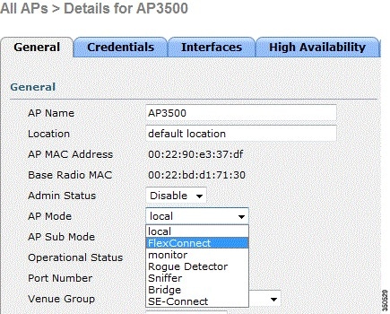
This option is also available on all the current WLC platforms.
Auto Convert Mode
This mode triggers the change on all the connected APs. It is recommended that FlexConnect WLC is deployed in a different mobility domain than existing WLC campus controllers before you enable this CLI:
(Cisco Controller) >config ap autoconvert ?
disable............Disables auto conversion of unsupported mode APs to supported modes when AP joins
flexconnect........Converts unsupported mode APs to flexconnect mode when AP joins monitor............Converts unsupported mode APs to monitor mode when AP joins
Step 1![]() The Auto-conversion feature is disabled by default, which can be verified by using this show command:
The Auto-conversion feature is disabled by default, which can be verified by using this show command:
(Cisco Controller) >show ap autoconvert
AP Autoconvert.................................. Disabled
Non-supported AP modes = Local Mode, Sniffer, Rogue Detector and Bridge.

This option is currently available only via CLIs.
Step 2![]() Performing config ap autoconvert flexconnect CLI converts all the APs in the network with non-supported AP mode to FlexConnect mode. Any APs that are already in FlexConnect or Monitor Mode are not affected.
Performing config ap autoconvert flexconnect CLI converts all the APs in the network with non-supported AP mode to FlexConnect mode. Any APs that are already in FlexConnect or Monitor Mode are not affected.
(Cisco Controller) >config ap autoconvert flexconnect
(Cisco Controller) >show ap autoconvert
AP Autoconvert.................................. FlexConnect
Step 3![]() Performing config ap autoconvert monitor CLI converts all the APs in the network with non-supported AP mode to Monitor mode. Any APs that are already in FlexConnect or Monitor mode are not affected.
Performing config ap autoconvert monitor CLI converts all the APs in the network with non-supported AP mode to Monitor mode. Any APs that are already in FlexConnect or Monitor mode are not affected.
(Cisco Controller >config ap autoconvert monitor
(Cisco Controller) >show ap autoconvert
AP Autoconvert................................. Monitor
There is no option to perform both config ap autoconvert flexconnect and config ap autoconvert monitor at the same time.
FlexConnect WGB/uWGB Support for Local Switching WLANs
From release 7.3 onwards, WGB/uWGB and wired/wireless clients behind WGBs are supported and will work as normal clients on WLANs configured for local switching.
After association, WGB sends the IAPP messages for each of its wired/wireless clients, and Flex AP will behave as follows:
- When Flex AP is in connected mode, it forwards all the IAPP messages to the controller and the controller will process the IAPP messages the same as Local mode AP. Traffic for wired/wireless clients will be switched locally from Flex APs.
- When AP is in standalone mode, it processes the IAPP messages, wired/wireless clients on the WGB must be able to register and de-register. Upon transition to connected mode, Flex AP will send the information of wired clients back to the controller. WGB will send registration messages three times when Flex AP transitions from Standalone to Connected mode.
Wired/Wireless clients will inherit WGB’s configuration, which means no separate configuration like AAA authentication, AAA override, and FlexConnect ACL is required for clients behind WGB.

Procedure
Step 1![]() No special configuration is needed in order to enable WGB/uWGB support on FlexConnect APs for WLANs configured for local switching as WGB. Also, clients behind WGB are treated as normal clients on local switching configured WLANs by Flex APs. Enable FlexConnect Local Switching on a WLAN.
No special configuration is needed in order to enable WGB/uWGB support on FlexConnect APs for WLANs configured for local switching as WGB. Also, clients behind WGB are treated as normal clients on local switching configured WLANs by Flex APs. Enable FlexConnect Local Switching on a WLAN.

Step 2![]() Set AP Mode to FlexConnect.
Set AP Mode to FlexConnect.

Step 3![]() Associate WGB with wired clients behind this configured WLAN.
Associate WGB with wired clients behind this configured WLAN.

Step 4![]() In order to check the details for WGB, go to Monitor > Clients, and select WGB from the list of clients.
In order to check the details for WGB, go to Monitor > Clients, and select WGB from the list of clients.
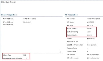
Step 5![]() In order to check the details of the wired/wireless clients behind WGB, go to Monitor > Clients, and select the client.
In order to check the details of the wired/wireless clients behind WGB, go to Monitor > Clients, and select the client.
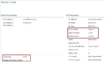
Limitations
- Wired clients behind WGB will always be on the same VLAN as WGN itself. Multiple VLAN support for clients behind WGB is not supported on Flex AP for WLANs configured for Local Switching.
- A maximum of 20 clients (wired/wireless) are supported behind WGB when associated to Flex AP on WLAN configured for local switching. This number is the same as what we have today for WGB support on Local mode AP.
- Web Auth is not supported for clients behind WGB associated on WLANs configured for local switching.
Support for an Increased Number of Radius Servers
Prior to release 7.4, the configuration of RADIUS servers at the FlexConnect group was done from a global list of RADIUS servers on the controller. The maximum number of RADIUS servers, which can be configured in this global list, is 17. With an increasing number of branch offices, it is a requirement to be able to configure a RADIUS server per branch site. In release 7.4 onwards, it will be possible to configure Primary and Backup RADIUS servers per FlexConnect group which may or may not be part of the global list of 17 RADIUS authentication servers configured on the controller.
An AP specific configuration for the RADIUS servers will also be supported. The AP specific configuration will have greater priority than the FlexConnect group configuration.
The existing configuration command at the FlexConnect Group, which needs the index of the RADIUS server in the global RADIUS server list on the controller, will be deprecated and replaced with a configuration command, which configures a RADIUS server at the Flexconnect Group using the IP address of the server and shared secret.
Summary
- Support for configuration of Primary and Backup RADIUS servers per FlexConnect group, which may or may not be present in the global list of RADIUS authentication servers.
- The maximum number of unique RADIUS servers that can be added on a WLC is the number of FlexConnect groups that can be configured on a given platform times two. An example is one primary and one secondary RADIUS server per FlexConnect group.
- Software upgrade from a previous release to release 7.4 will not cause any RADIUS configuration loss.
- The deletion of the primary RADIUS server is allowed without having to deleting the secondary RADIUS server. This is consistent with the present FlexConnect group configuration for the RADIUS server.
Procedure
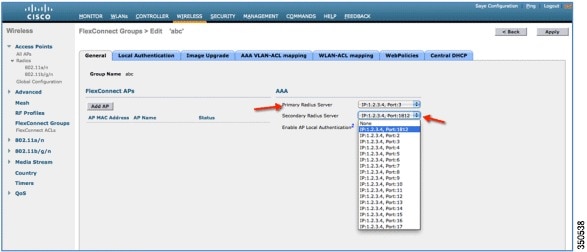
Step 1![]() Mode of configuration prior to release 7.4.
Mode of configuration prior to release 7.4.
A maximum of 17 RADIUS servers can be configured under the AAA Authentication configuration.
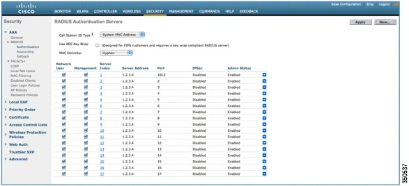
Step 2![]() Primary and Secondary RADIUS servers can be associated with a FlexConnect Group using a drop-down list comprising of RADIUS servers configured on the AAA Authentication page.
Primary and Secondary RADIUS servers can be associated with a FlexConnect Group using a drop-down list comprising of RADIUS servers configured on the AAA Authentication page.
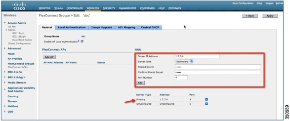
Step 3![]() Mode of configuration at FlexConnect Group in release 7.4.
Mode of configuration at FlexConnect Group in release 7.4.
Primary and Secondary RADIUS servers can be configured under the FlexConnect Group using an IP address, port number and Shared Secret.
Enhanced Local Mode (ELM)
ELM is supported on the FlexConnect solution. Refer to the best practices guide on ELM for more information.
Guest Access Support in FlexConnect
Figure 7 Guest Access Support in FlexConnect
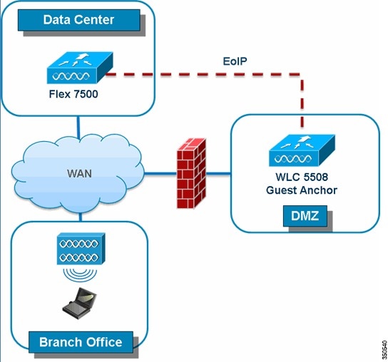
FlexConnect WLC will allow and continue to support creation of EoIP tunnel to your guest anchor controller in DMZ. For best practices on the wireless guest access solution, refer to the Guest Deployment Guide.
Support for PEAP and EAP-TLS Authentication
FlexConnect AP can be configured as a RADIUS server for LEAP and EAP-FAST client authentication. In standalone mode and also when local authentication feature is enabled on the WLANs, FlexConnect AP will do dot1x authentication on the AP itself using the local radius. With controller release 7.5, PEAP and EAP-TLS EAP methods are also supported.
Certificate Generation for EAP-TLS
The following steps are needed on the WLC and the client in order to authenticate the client to the FlexConnect AP using EAP-TLS authentication.
1.![]() Generate device certificate for the WLC.
Generate device certificate for the WLC.
2.![]() Get device certificate signed by CA server.
Get device certificate signed by CA server.
3.![]() Generate CA certificate from the CA server.
Generate CA certificate from the CA server.
4.![]() Import device and CA certificate into the WLC in.pem format.
Import device and CA certificate into the WLC in.pem format.
1.![]() Generate client certificate.
Generate client certificate.
2.![]() Get client certificate signed by CA server.
Get client certificate signed by CA server.
3.![]() Generate CA certificate from the CA server.
Generate CA certificate from the CA server.
4.![]() Install client and CA certificate on the client.
Install client and CA certificate on the client.
Detailed steps on how to accomplish the above steps are listed in Document-100590 ( http://www.cisco.com/en/US/products/ps6366/products_configuration_example09186a008093f1b9.shtml)

Configuration of EAP-TLS on FlexConnect AP
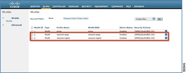
1.![]() Create WLAN for Local Switching and Local Authentication.
Create WLAN for Local Switching and Local Authentication.
In the example below, two WLANs have been created, one for EAP-TLS and the other for PEAP authentication.
Figure 9 WLAN Configuration for PEAP and EAP-TLS
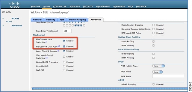
2.![]() Enable FlexConnect Local Switching and FlexConnect Local Auth
Enable FlexConnect Local Switching and FlexConnect Local Auth
Figure 10 WLANs for Local Switching and Local Authentication
3.![]() Enable AP Local Authentication.
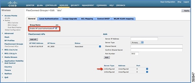
Enable AP Local Authentication.
Enable the Enable AP Local Authentication check box on the FlexConnect groups edit page. Radius Servers on the FlexConnect group must be ‘Unconfigured’. If any RADIUS servers are configured on the FlexConnect group, the AP tries to authenticate the wireless clients using the RADIUS servers first. AP Local Authentication is attempted only if no RADIUS servers are found, either because the RADIUS servers timed out or no RADIUS servers were configured.
Figure 11 FlexConnect Group Configuration for AP Local Authentication
4.![]() Selecting EAP methods will now have two more options, PEAP and EAP-TLS under the FlexConnect group with the existing LEAP and EAP-FAST options.
Selecting EAP methods will now have two more options, PEAP and EAP-TLS under the FlexConnect group with the existing LEAP and EAP-FAST options.
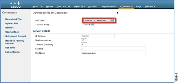
a.![]() Current controller release supports downloading of EAP device and root (CA) certificates to the controller and the same is stored in PEM format on the flash.
Current controller release supports downloading of EAP device and root (CA) certificates to the controller and the same is stored in PEM format on the flash.
Figure 12 Downloading Vendor Device Certificate
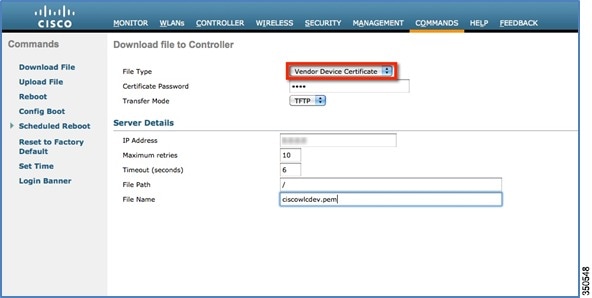
Figure 13 Downloading Vendor CA Certificate
b.![]() With release 7.5, these certificates will be used for authenticating clients using EAP-TLS. Both the device and root certificates will be downloaded to all the FlexConnect APs in the FlexConnect group if the EAP-TLS method is enabled, and the same is used at the AP to authenticate the clients.
With release 7.5, these certificates will be used for authenticating clients using EAP-TLS. Both the device and root certificates will be downloaded to all the FlexConnect APs in the FlexConnect group if the EAP-TLS method is enabled, and the same is used at the AP to authenticate the clients.
c.![]() When a new AP joins the group, certificates will be pushed to the AP along with other configurations. The user has to download the EAP device and Root certificates to controller prior to enabling EAP-TLS on the FlexConnect group.
When a new AP joins the group, certificates will be pushed to the AP along with other configurations. The user has to download the EAP device and Root certificates to controller prior to enabling EAP-TLS on the FlexConnect group.
d.![]() Upon receiving a certificate message from the controller, the AP will import these certificates, store them in memory and use them for authenticating clients.
Upon receiving a certificate message from the controller, the AP will import these certificates, store them in memory and use them for authenticating clients.
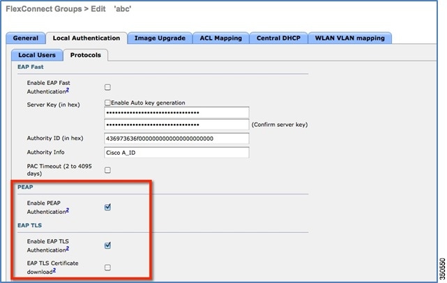
e.![]() EAP TLS Certificate Download option is provided to push any updated certificates to the AP.
EAP TLS Certificate Download option is provided to push any updated certificates to the AP.
Figure 14 Enabling PEAP and EAP TLS on AP Local Authentication under FlexConnect Group
Certificate Files on AP
Four files are downloaded to the AP, when EAP-TLS is enabled.
- eapdev.pem.ca – This is the CA (root) certificate.
- eapdev.pem.crt –This is the public certificate of the device.
- eapdev.pem.prv –This is the RSA private key of the device.
- eapdevpwd – This is the password file to protect the private key.
Figure 15 Files Stored in the Flash on AP

Client Configuration
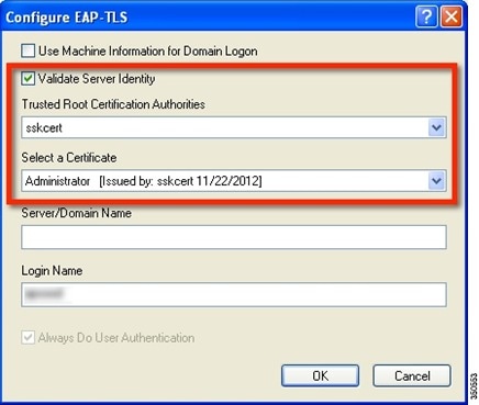
Configure the wireless profile for EAP-TLS by selecting EAP Type EAP-TLS and specifying the Trusted Root certificate Authorities and the client certificate.
Figure 16 Wireless Profile for EAP-TLS

Figure 17 Validate Server Identity
Once the client is connected, Server Based Authentication will reflect EAP-TLS.
Figure 18 Client Authentication using EAP-TLS

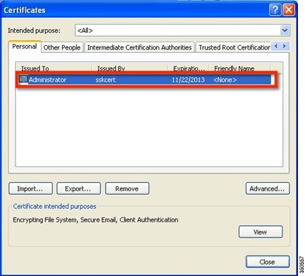
Client Certificates
The Trusted Root and Client Certificates can be viewed as follows (These are the certificates as generated earlier)
Figure 19 Certificates on Client
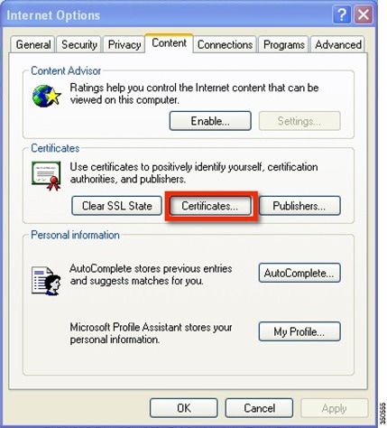
Figure 20 Trusted Root (CA) Certificate on Client
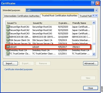
Figure 21 Trusted Client Certificate
Show Commands
The EAP type of the client will be reflected on the WLC and can be seen in the output of show client detail
Figure 22 EAP Type for Client Authenticated using EAP-TLS

EAP-PEAP
PEAP (EAP-MSCHAPv2 and EAP-GTC) EAP Type is supported with release 7.5 and Users need to be added on the WLC as shown below. A maximum of 100 users can be added per FlexConnect group.
Client Configuration
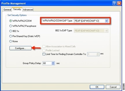
Selecting EAP Type EAP-MSCHAPv2 or GTC can configure the wireless profile for EAP-PEAP.
Figure 24 Wireless Profile for EAP-PEAP (EAP-MSCHAPv2)
Users created on the controller need to be configured on the client.
Figure 25 User Name and Password for PEAP
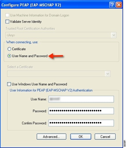
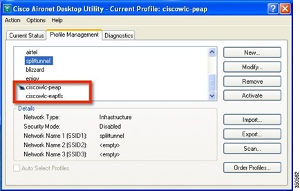
Figure 26 Cisco Aironet Desktop Utility Profile Management
Once the client is connected, Server Based Authentication will reflect PEAP(EAP-MSCHAPv2)
Figure 27 Client Authentication using PEAP(EAP-MSCHAPv2)
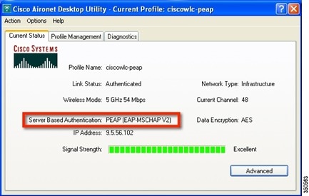
Once the client is authenticated, the EAP Type can be seen under the Client Detail page.
Figure 28 Web GUI Client Details

Show Commands
The EAP type of the client will be reflected on the WLC and can be seen in the output of show client detail
Figure 29 EAP Type of Client Authenticated using PEAP
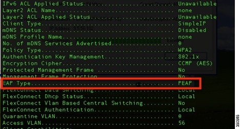
CLI Support for PEAP and EAP-TLS on FlexConnect APs
Two new CLIs have been added to configure PEAP and EAP-TLS from the controller.
config flexconnect group <groupName> radius ap peap <enable | disable>
config flexconnect group <groupName> radius ap eap-tls <enable | disable>
A CLI for certificate download has been added as well.
config flexconnect group <groupName> radius ap eap-cert download
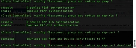
Configurations at the AP can be seen from the console.
Figure 30 CLI Commands on AP Console

The following commands can be used to troubleshoot this feature:
WLAN-VLAN mapping at FlexConnect Group Level
Prior to release 7.5, WLAN to VLAN mapping was done on a per AP basis.
With increasing number of APs in a deployment, there is a need to provide the capability of adding WLAN to VLAN maps from the FlexConnect group. This will be supported in release 7.5.
This will push the WLAN to VLAN mapping to all the APs present in the FlexConnect group. The FlexConnect level configuration will have a higher precedence compared to the WLAN-VLAN mapping configured on the WLAN.
WLAN-VLAN Mapping Inheritance
- WLAN level WLAN-VLAN mapping has the lowest precedence.
- Higher precedence mapping will override the mapping of lower precedence
- AP level WLAN-VLAN mapping has the highest precedence
- On deletion of a higher precedence mapping, the next highest precedence mapping will take effect.
The following figure depicts the order of precedence as it refers to WLAN-VLAN mapping at the WLAN, FlexConnect group and at the AP.
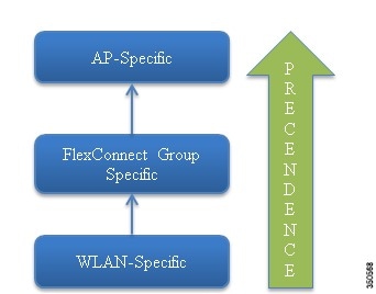
GUI Configuration
1.![]() Create WLAN for Local Switching
Create WLAN for Local Switching
Figure 32 WLAN for Local Switching
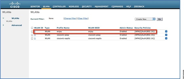
Figure 33 FlexConnect Local Switching

The WLAN is mapped to the management VLAN 56.
Figure 34 WLAN Mapped to VLAN 56 Management Interface
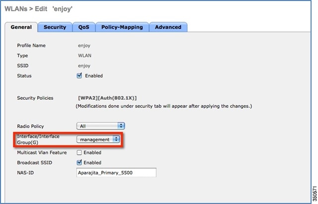
Figure 35 WLAN Mapped to VLAN 56 as Per WLAN-Specific Mapping
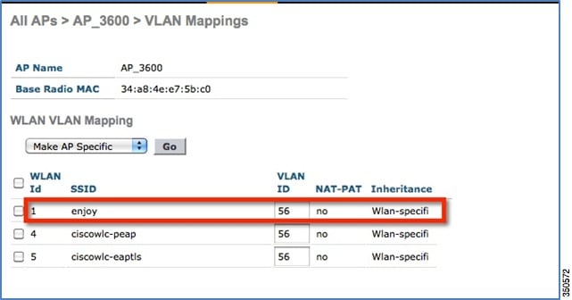
When a client connects to this WLAN, it will get an IP in VLAN 56.
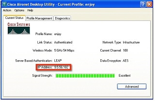
2.![]() Create WLAN-VLAN mapping under FlexConnect Groups. This capability is the new feature in release 7.5.
Create WLAN-VLAN mapping under FlexConnect Groups. This capability is the new feature in release 7.5.
Figure 37 WLAN Mapped to VLAN 57 under FlexConnect Group
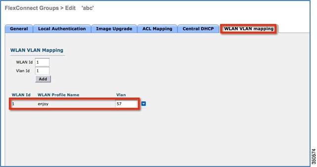
WLAN-VLAN mappings can be viewed per AP from the VLAN Mappings page
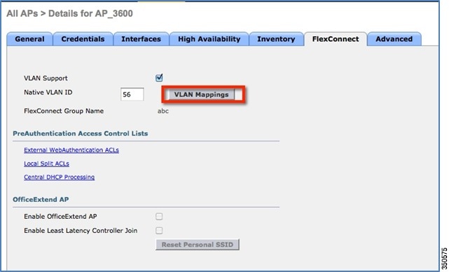
In this example, the WLAN is mapped to VLAN 57 on the FlexConnect Group, since the Group-specific mappings take precedence over WLAN-specific mappings.
Figure 39 WLAN 1 Mapped to VLAN 57 as Per Group-Specific Configuration Inheritance
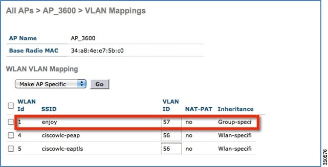
The client is assigned an IP address in VLAN 57.
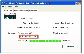
3.![]() To create a WLAN-VLAN mapping at the AP, select Make AP Specific under VLAN Mappings.
To create a WLAN-VLAN mapping at the AP, select Make AP Specific under VLAN Mappings.
Once this is done, the WLAN is mapped to VLAN 58 since AP-specific mappings take precedence over Group-specific and WLAN-specific mappings.
Figure 41 WLAN Mapped to VLAN 58 as Per AP-Specific Mapping Inheritance
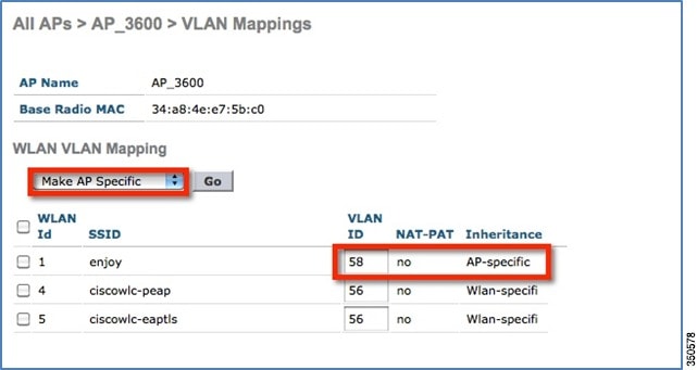
The client is assigned an IP address in VLAN 58.
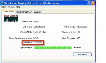
CLI Configuration
The following CLIs have been added as part of this feature:
-
config flexconnect group <group> wlan-vlan wlan <wlan-id> add vlan <vlan-id> -
config flexconnect group <group> wlan-vlan wlan <wlan-id> delete -
config ap flexconnect vlan remove wlan <wlan_id> <ap_name>
Figure 43 WLAN-VLAN Configuration at FlexConnect Group from CLI

The command show flexconnect group detail can be used to see the WLAN-VLAN mapping for the FlexConnect group
Figure 44 show flexconnect group detail Output
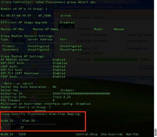
The command show ap config general <AP name> can be used to view the WLAN-VLAN mappings per AP.
Figure 45 show ap config general Output
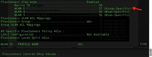
The following commands can be used to troubleshoot this feature:
Client ACL Support
Prior to release 7.5, we support FlexConnect ACLs on the VLAN. We also support AAA override of VLANs. If a client gets an AAA override of VLAN, it is placed on the overridden VLAN and the ACL on the VLAN applies for the client. If an ACL is received from the AAA for locally switched clients, we ignore the same. With release 7.5, we address this limitation and provide support for client based ACLs for locally switched WLANs.
Client ACL Overview
a.![]() This feature allows application of Per-Client ACL for locally switching WLANs.
This feature allows application of Per-Client ACL for locally switching WLANs.
b.![]() Client ACL is returned from the AAA server on successful Client L2 Authentication/Web Auth as part of Airespace Radius Attributes.
Client ACL is returned from the AAA server on successful Client L2 Authentication/Web Auth as part of Airespace Radius Attributes.
c.![]() The controller will be used to pre-create the ACLs at the AP. When the AP receives the ACL configuration, it will create the corresponding IOS ACL. Once, AAA server provides the ACL, the client structure will be updated with this information.
The controller will be used to pre-create the ACLs at the AP. When the AP receives the ACL configuration, it will create the corresponding IOS ACL. Once, AAA server provides the ACL, the client structure will be updated with this information.
d.![]() There will be configuration per FlexConnect group as well as per AP. A maximum of 16 ACLs can be created for a FlexConnect group and a maximum of 16 ACLs can be configured per-AP.
There will be configuration per FlexConnect group as well as per AP. A maximum of 16 ACLs can be created for a FlexConnect group and a maximum of 16 ACLs can be configured per-AP.
e.![]() In order to support fast roaming (CCKM/PMK) for the AAA overridden clients, the controller will maintain these ACL in the cache and push them to all APs which are part of the FlexConnect group.
In order to support fast roaming (CCKM/PMK) for the AAA overridden clients, the controller will maintain these ACL in the cache and push them to all APs which are part of the FlexConnect group.
f.![]() In the case of central authentication, when the controller receives the ACL from the AAA server, it will send the ACL name to the AP for the client. For locally authenticated clients, the ACL will be sent from the AP to the controller as part of CCKM/PMK cache, which will then be distributed to all APs belonging to the FlexConnect-group.
In the case of central authentication, when the controller receives the ACL from the AAA server, it will send the ACL name to the AP for the client. For locally authenticated clients, the ACL will be sent from the AP to the controller as part of CCKM/PMK cache, which will then be distributed to all APs belonging to the FlexConnect-group.
g.![]() Maximum of 16 Client ACLs per FlexConnect group, maximum of 16 Client ACLs per-AP
Maximum of 16 Client ACLs per FlexConnect group, maximum of 16 Client ACLs per-AP
h.![]() Total of 96 ACLs can be configured on the AP (32 VLAN-ACL, 16 WLAN-ACL, 16 Split tunnel, 16 FlexConnect Client ACL, 16 AP Client ACL), each ACL with 64 rules.
Total of 96 ACLs can be configured on the AP (32 VLAN-ACL, 16 WLAN-ACL, 16 Split tunnel, 16 FlexConnect Client ACL, 16 AP Client ACL), each ACL with 64 rules.
i.![]() The ACL will be applied on the dot11 side for the client in question. This ACL will be applied in addition to the VLAN ACL, which is applied on the VLAN of the Ethernet interface of the AP.
The ACL will be applied on the dot11 side for the client in question. This ACL will be applied in addition to the VLAN ACL, which is applied on the VLAN of the Ethernet interface of the AP.
j.![]() Client ACL applied in addition to VLAN-ACL, both can exist simultaneously and are applied serially.
Client ACL applied in addition to VLAN-ACL, both can exist simultaneously and are applied serially.

Steps to Configure Client ACL
1.![]() Create a Local Switching WLAN, which is either centrally switched or locally switched.
Create a Local Switching WLAN, which is either centrally switched or locally switched.
Figure 46 Create Local Switching WLAN
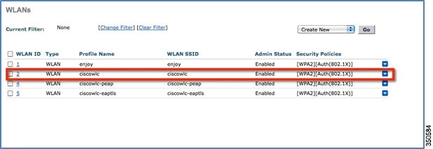
2.![]() Turn on AAA override for the WLAN
Turn on AAA override for the WLAN
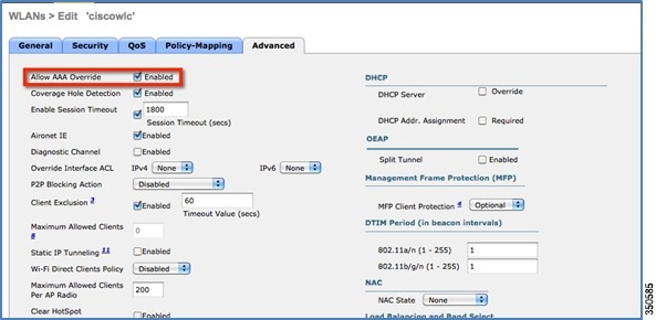
FlexConnect ACL can be configured from the Security page as well as from the Wireless page.
Figure 47 Configure FlexConnect ACL
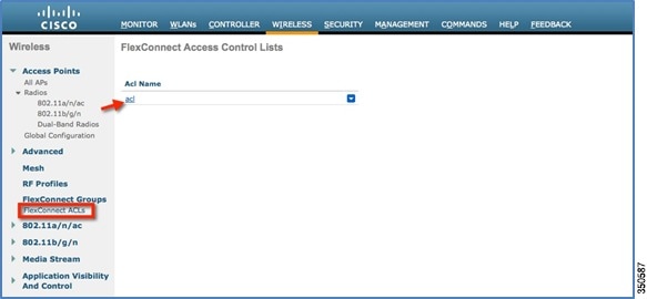
4.![]() Assign the FlexConnect ACL to the FlexConnect group or to the AP
Assign the FlexConnect ACL to the FlexConnect group or to the AP
Figure 48 ACL Mapping on FlexConnect Group
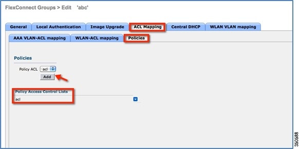
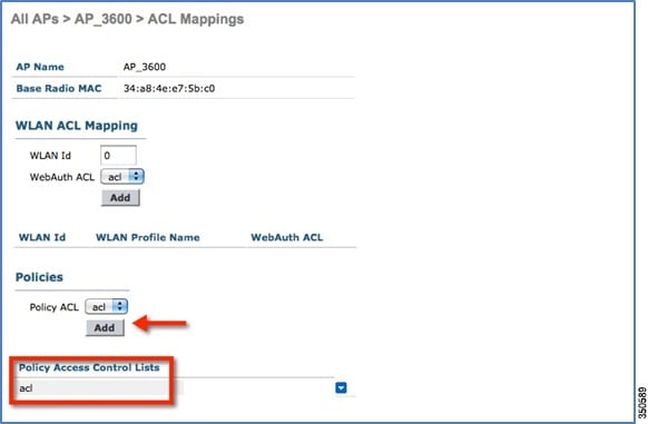
5.![]() Configure the Airespace attribute on the Radius/Cisco ACS server/ISE.
Configure the Airespace attribute on the Radius/Cisco ACS server/ISE.
Figure 50 Aire-Acl-Name on Cisco ACS Server
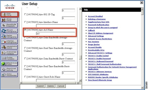
Figure 51 Airespace ACL Name on ISE
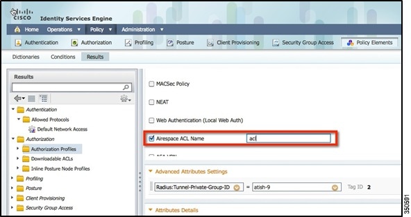
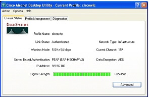
CLI Configuration
The Client ACL can be seen on the AP using the commands show access-list and show controllers dot11Radio
Figure 52 show access-lists Output


http://www.cisco.com/en/US/products/ps11635/products_tech_note09186a0080b7f141.shtml
Guidelines
- Prior to AAA sending the client ACL, the ACL should be pre-created on the group or AP. The ACL will not be dynamically downloaded to the AP at the time of client join.
- A maximum of 96 ACLs can be configured on the AP.
- Each ACL will have a maximum of 64 rules.
- If client is already authenticated, and ACL name is changed on the radius, then client will have to do a full authentication again to get the correct client ACL.
- Since ACL not saved in cache at the controller, if the AP reboots/crashes, its cache will not be updated and the client will have to do full authentication for correct client ACL to be applied.
- If an ACL is returned from the AAA server but the corresponding ACL is not present on the AP, the client will be de-authenticated. A log message will be generated at the AP and WLC console.
*Mar 4 09:20:43.255: %LWAPP-3-CLIENT_ACL_ENTRY_NOT_EXIST: Deleting Mobile for 0040.96b8.d4be: CLIENT ACL not exist on AP
*spamApTask7: Mar 04 14:51:03.989: #HREAP-3-CLIENT_ACL_ENTRY_NOT_EXIST: spam_lrad.c:36670 The client 00:40:96:b8:d4:be could not join AP : 34:a8:4e:e7:5b:c0 for slot 1, Reason: acl returned from RADIUS/local policy not present at AP
Introduction
Cisco Unified Wireless Network (CUWN) release 8.0 introduces a new feature—VideoStream for Local Switching, for branch office deployments. This feature enables the wireless architecture to deploy multicast video streaming across the branches, just like it is currently possible for enterprise deployments. This feature recompenses the drawbacks that degrade the video delivery as the video streams and clients scale in a branch network. VideoStream makes video multicast to wireless clients more reliable and facilitates better usage of wireless bandwidth in the branch.
Components Used
VideoStream feature for Local Switching is available in CUWN software version 8.0. This feature is supported on all wireless LAN controllers (WLANs) and newer generation indoor access points (APs). This feature is unavailable on autonomous access points.
Supported Wireless Hardware and Software
VideoStream is supported on all the following Cisco Wireless LAN controllers:
- Cisco 5500 Controller
- Cisco 7510 Controller
- Cisco 8510 Controller
- Cisco WiSM-2 Controller
- Cisco 2504 Controller
- vWLC
IGMPv2 is the supported version on all of the controllers.
VideoStream is supported on 802.11n models of APs consisting of Cisco Aironet 1140, 1250, 1260, 1520, 1530, 1550, 1600, 2600, 3500, 3600 series APs and 802.11ac models 3700 and 2700 series APs.
Theory of Operation
Before going into details about the VideoStream feature, you should understand some of the shortfalls in Wi-Fi multicast. 802.11n is a prominently discussed wireless technology for indoor wireless deployments. Equally prominent requirement is seen in multimedia service on an enterprise and branch network, in particular, video. Multicast does not provide any MAC layer recovery on multicast and broadcast frames. Multicast and broadcast packets do not have an Acknowledgement (ACK), and all packet delivery is best effort. Multicast over wireless with 802.11a/b/g/n does not provide any mechanism for reliable transmission.
Wireless deployments are prone to interference, high channel utilization, and low SNR at the edge of the cell. There are also many clients sharing the same channel but have different channel conditions, power limitations, and client processing capabilities. Therefore, multicast is not a reliable transmission protocol to all the clients in the same channel because each client has different channel conditions.
Wireless multicast does not prioritize the video traffic even though it is marked as Differentiated Service Code Point (DSCP) by the video server. The application will see a loss of packets with no ACK, and retries to the delivery will be bad. In order to provide reliable transmissions of multicast packet, it is necessary that the network classify queues and provisions using Quality of Service (QoS). This virtually removes the issue of unreliability by eliminating dropped packets and delay of the packets to the host by marking the packets and sorting them to the appropriate queue.
Even though the 802.11n, and now 802.11ac, adaptation has gained momentum both with the network and clients, wireless multicast has not been able to use the 802.11n and 802.11ac data rates. This has also been one of the factors for an alternate mechanism for wireless multicast propagation.
VideoStream
VideoStream provides efficient bandwidth utilization by removing the need to broadcast multicast packets to all WLANs on the AP regardless if there is a client joined to a multicast group. In order to get around this limitation, the AP has to send multicast traffic to the host using Unicast forwarding, only on the WLAN that the client is joined and at the data rate the client is joined at.
VideoStream can be enabled globally on the controller. The feature can also be enabled at the WLAN level, and provides more control to the administrator to identify specific video streams for Multicast Direct functionality.
Stream Admission
As mentioned earlier, while video is an efficient, high-impact means of communication, it is also very bandwidth intensive, and as is seen, not all video content is prioritized the same. From earlier discussion it is clear that organizations investing in video cannot afford to have network bandwidth consumed without any prioritization of business-critical media.
Multicast to Unicast
By enabling 802.11n data rates and providing packet error correction, multicast-to-unicast capabilities of Cisco VideoStream enhances reliability of delivering streaming video over Wi-Fi beyond best-effort features of traditional wireless networks.
A wireless client application subscribes to an IP multicast stream by sending an IGMP join message. With reliable multicast, this request is snooped by the infrastructure, which collects data from the IGMP messages. The AP checks the stream subscription and configuration. A response is sent to the wireless client attached to the AP in order to initiate reliable multicast once the stream arrives. When the multicast packet arrives, the AP replicates the multicast frame and converts it to 802.11 unicast frames. Finally, a reliable multicast service delivers the video stream as unicast directly to the client.
Higher Video Scaling on Clients
With Cisco VideoStream technology, all of the replication is done at the edge (on the AP), thus utilizing the overall network efficiently. At any point in time, there is only the configured media stream traversing the network, because the video stream is converted to unicast at the APs based on the IGMP requests initiated by the clients. Some other vendor implementations do a similar conversion of multicast to unicast, but do it inefficiently as evidenced by the load put on the wired network to support the stream.
Switch Configuration
VideoStream can be deployed on an existing branch wide wired and wireless network. The overall implementation and maintenance costs of a video over wireless network are greatly reduced. The assumption is that the wired network is multicast enabled. In order to verify that the access switch is part of the layer 3 network, connect a client machine to the switchport and verify if the client machine is able to join a multicast feed.
Show run | include multicast displays if multicast is enabled on the layer 3 switch else if not enabled for multicast, you can enable multicast by executing the following command on the switch:
L3_Switch#show run | include multicast
ip multicast-routing distributed
Depending on the type of Protocol Independent Routing (PIM) configuration on the wired network, the layer 3 switch is configured either in PIM Sparse mode or in PIM dense mode. There is also a hybrid mode, PIM sparse-dense mode which is widely used.
ip address 9.5.56.1 255.255.255.0
show ip igmp interfaces display the SVI interfaces that are participating in the IGMP membership. This command displays the version of IGMP configured on the switch or the router. The IGMP activity on the interface can also be verified in the form of IGMP join and leave messages by the clients.
L3_Switch#show ip igmp interface
Vlan56 is up, line protocol is up
Internet address is 9.5.56.1/24
Current IGMP host version is 2
Current IGMP router version is 2
IGMP query interval is 60 seconds
IGMP configured query interval is 60 seconds
IGMP querier timeout is 120 seconds
IGMP configured querier timeout is 120 seconds
IGMP max query response time is 10 seconds
Last member query response interval is 1000 ms
Inbound IGMP access group is not set
IGMP activity: 6 joins, 3 leaves
Multicast routing is enabled on interface
Multicast designated router (DR) is 9.5.56.1 (this system)
IGMP querying router is 9.5.56.1 (this system)
Multicast groups joined by this system (number of users):
The above configuration can be verified by running the show ip mroute command on the layer 3 switch. The above configuration has certain entries that need to be looked into. The special notation of (Source, Group), pronounced “S, G” where the source “S” is the source IP address of the multicast server and “G” is the Multicast Group Address that a client has requested to join. If the network has many sources, you will see on the routers an (S,G) for each of the source IP address and Multicast Group addresses. This output displayed below also has information of outgoing and incoming interfaces.
Flags: D - Dense, S - Sparse, B - Bidir Group, s - SSM Group, C - Connected,
L - Local, P - Pruned, R - RP-bit set, F - Register flag,
T - SPT-bit set, J - Join SPT, M - MSDP created entry, E - Extranet,
X - Proxy Join Timer Running, A - Candidate for MSDP Advertisement,
U - URD, I - Received Source Specific Host Report,
Z - Multicast Tunnel, z - MDT-data group sender,
Y - Joined MDT-data group, y - Sending to MDT-data group,
Outgoing interface flags: H - Hardware switched, A - Assert winner
Interface state: Interface, Next-Hop or VCD, State/Mode
(*, 239.255.255.250), 4d20h/00:02:35, RP 0.0.0.0, flags: DC
Incoming interface: Null, RPF nbr 0.0.0.0
Vlan56, Forward/Sparse-Dense, 4d20h/stopped
(*, 229.77.77.28), 4d15h/00:02:36, RP 0.0.0.0, flags: DC
Incoming interface: Null, RPF nbr 0.0.0.0
Vlan56, Forward/Sparse-Dense, 00:24:34/stopped
(*, 224.0.1.40), 5d17h/00:02:41, RP 0.0.0.0, flags: DCL
Controller Configuration
Enable Global Multicast Mode and IGMP snooping on the controller as shown below:
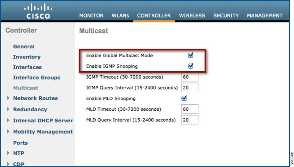
(Cisco Controller) >config network multicast global enable
(Cisco Controller) >config network multicast igmp snooping enable
To enable the VideoStream feature globally on the controller, navigate to Wireless > Media Stream > General and check the Multicast Direct Feature check box. Enabling the feature here populates some of the configuration parameters on the controller for VideoStream.
Figure 55 Enable VideoStream - Global
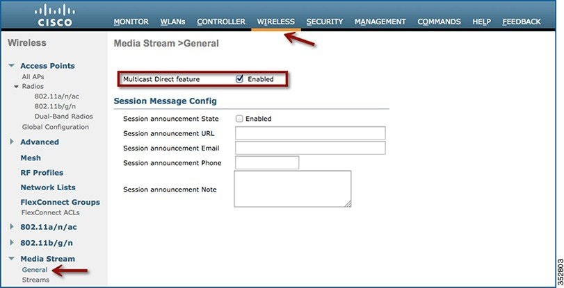
(Cisco Controller) >config media-stream multicast-direct ?
enable Enable Global Multicast to Unicast Conversion
disable Disable Global Multicast to Unicast Conversion
The multicast direct button under WLAN > QoS appears on if the feature is enabled globally.
This provides the flexibility to enable VideoStream feature per SSID and is described later in this document.
Turn on Local Switching under WLAN > Advanced and ensure that the APs in the setup are in FlexConnect mode.
Figure 56 Enable Local Switching on WLAN
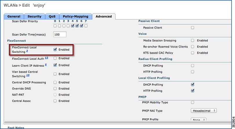
Figure 57 Change AP Mode to FlexConnect
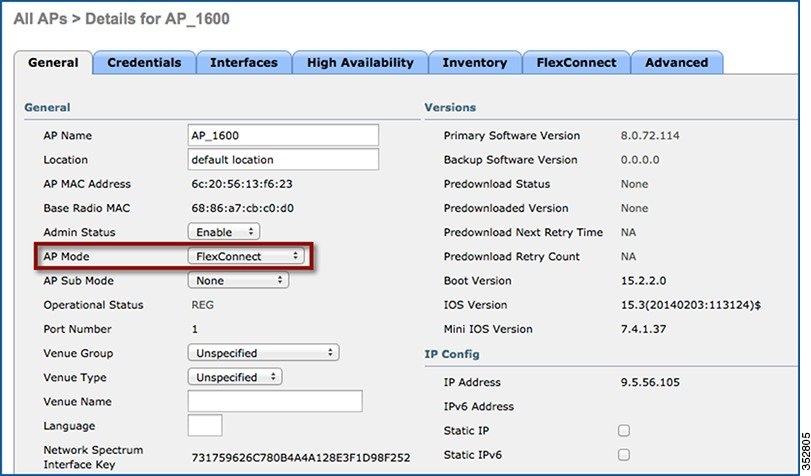
Add Media Stream Configuration
To add a multicast stream to the controller, navigate to Wireless > Media Stream > Streams and click Add New.
Figure 58 Media Stream Configuration
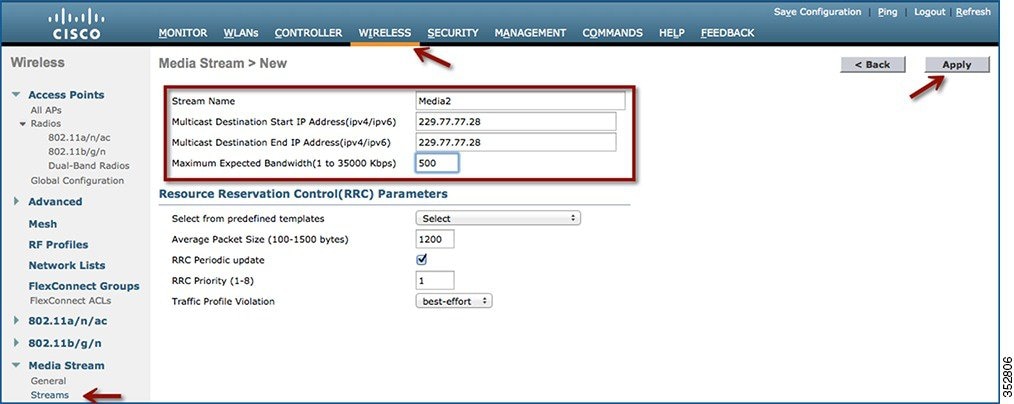
For configuration using CLI use:
configure media-stream add multicast-direct <media-stream-name> <start-IP> <end-IP> [template | detail <bandwidth> <packet-size> <Re-evaluation> video <priority> <drop|fallback>]
As mentioned it is necessary that the administrator is aware of the video characteristic streaming through a controller. A true balance must be drawn when the streams configuration are added. For example, if the stream bit rate varies between 1200 Kbps and 1500 Kbps the stream must be configured for a bandwidth of 1500 Kbps. If the stream is configured for 3000 Kbps then you will have lesser video client serviced by the AP. Similarly, configuring for 1000 Kbps will cause pixelization, bad audio, and bad user experience.
The multicast destination start IP address and end IP address can be the same address as shown in Figure 58. You can also configure a range of multicast address on the controller. There is a limitation of 100 on the number of multicast addresses entries or the number of stream entries that will be pushed to the APs.
Enabling VideoStream – WLAN
One or all WLANs/SSIDs configured can be enabled for streaming video with VideoStream. This is another configuration step that can control the enabling of the VideoStream feature. Enabling or disabling the VideoStream feature is non-disruptive. Click WLAN > <WLAN ID> > QoS.
Figure 59 Enable VideoStream – WLAN
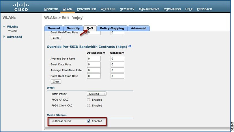
Configure the Quality of Service (QoS) to Gold (video) to stream video to wireless client at a QoS value of gold (4). This will only enable video quality of service to wireless clients joined to a configured stream on the controller. The rest of the clients will be enabled for appropriate QoS. To enable Multicast Direct on the WLAN, check the Multicast Direct check box as shown in Figure 59. This will enable the WLAN to service wireless clients with the VideoStream feature.
(Cisco Controller) > config wlan media-stream multicast-direct 1 ?
enable Enables Multicast-direct on the WLAN
disable Disables Multicast-direct on the WLAN.
All wireless clients requesting to join a stream will be assigned video QoS priority on admission. Wireless client streaming video prior to enabling the feature on the WLAN will be streaming using normal multicast. Enabling the feature switch the clients to multicast-direct automatically on the next IGMP snooping interval. Legacy multicast can be enabled on the WLAN by not checking the Multicast Direct feature. This will show that wireless clients streaming video are in Normal Multicast mode.
Verifying VideoStream Functionality
Make sure the wireless clients are associated to the access point(s), and are configured for a correct interface. As seen in the Figure 60, there are three clients associated to one AP. All three clients have an IP address from VLAN 56 (SSID name—enjoy).The associated clients have an IP address and good uplink connectivity to the AP.
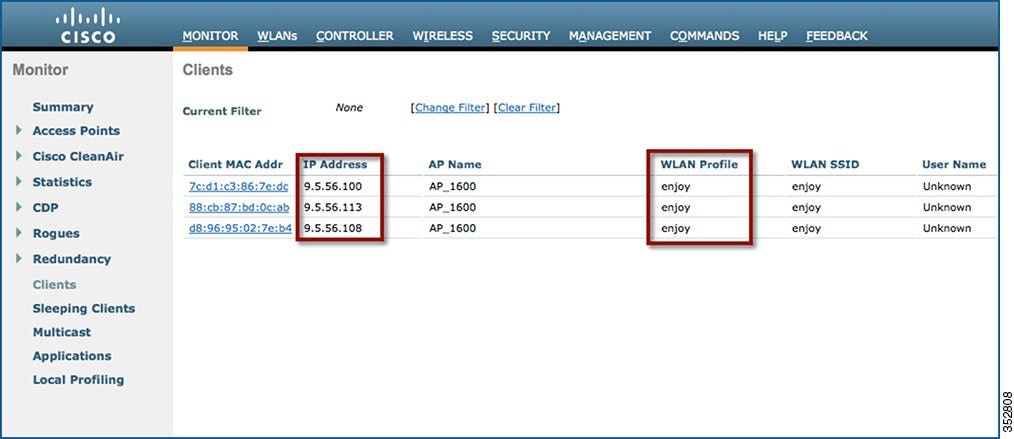
Enable streaming on the wired side by connecting a video server with a configured multicast address 229.77.77.28. Refer the following link to know how to stream from a Video Sever: https://wiki.videolan.org/Documentation:Streaming_HowTo_New/#Streaming_using_the_GUI
Step 1![]() Join wireless clients to the multicast streaming video.
Join wireless clients to the multicast streaming video.

Note![]() Use VLC player to stream and watch video.
Use VLC player to stream and watch video.
Step 2![]() Double click on the VLC icon on your desktop. Click Media > Open Network stream. Choose
Double click on the VLC icon on your desktop. Click Media > Open Network stream. Choose
Protocol = UDP, Address = 229.77.77.28, Port = 1234 in the format udp://@229.77.77.28:1234
Flags: D - Dense, S - Sparse, B - Bidir Group, s - SSM Group, C - Connected,
L - Local, P - Pruned, R - RP-bit set, F - Register flag,
T - SPT-bit set, J - Join SPT, M - MSDP created entry, E - Extranet,
X - Proxy Join Timer Running, A - Candidate for MSDP Advertisement,
U - URD, I - Received Source Specific Host Report,
Z - Multicast Tunnel, z - MDT-data group sender,
Y - Joined MDT-data group, y - Sending to MDT-data group,
Outgoing interface flags: H - Hardware switched, A - Assert winner
Interface state: Interface, Next-Hop or VCD, State/Mode
(*, 239.255.255.250), 4d20h/00:02:47, RP 0.0.0.0, flags: DC
Incoming interface: Null, RPF nbr 0.0.0.0
Vlan56, Forward/Sparse-Dense, 4d19h/stopped
(*, 229.77.77.28), 4d15h/00:02:44, RP 0.0.0.0, flags: DC
Incoming interface: Null, RPF nbr 0.0.0.0
Vlan56, Forward/Sparse-Dense, 00:17:24/stopped
(*, 224.0.1.40), 5d17h/00:02:53, RP 0.0.0.0, flags: DCL
Incoming interface: Null, RPF nbr 0.0.0.0
Vlan56, Forward/Sparse-Dense, 5d17h/stopped
It is observed that the MAC address of the wireless clients is in a Multicast-Direct Allowed State.
Figure 61 FlexConnect VideoStream Clients
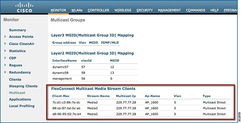
The Wireshark capture on the client shows the Multicast to Unicast Video Stream. The Ethernet header contains the MAC address of the client as the Destination MAC address, for example, 7c:d1:c3:86:7e:dc.
Figure 62 Wireshark Capture Depicting mc2uc
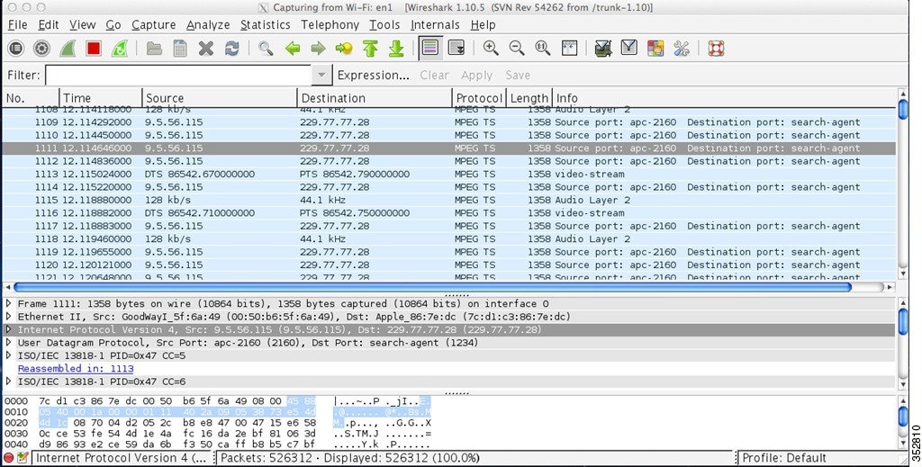
Limitations
The limitations to this feature scope include:
1.![]() There is no admission control for local switched clients’ multicast video requests, which means always admit the configured video stream subscriptions as mc2uc.
There is no admission control for local switched clients’ multicast video requests, which means always admit the configured video stream subscriptions as mc2uc.
2.![]() Due to the limit of CAPWAP payload length, only the first 100 media-streams will be pushed from the controller to the AP in this release. For example,
Due to the limit of CAPWAP payload length, only the first 100 media-streams will be pushed from the controller to the AP in this release. For example,
config media-stream add multicast-direct stream1 225.0.0.1 225.0.0.10 template coarse, is considered as one entry.
3.![]() Roaming support is limited to adding mobile payload. Whenever the client roams to another AP, the WLC will add the entry for the client in the mc2uc table. This means that roaming in standalone mode of FlexConnect AP will not be supported for this feature.
Roaming support is limited to adding mobile payload. Whenever the client roams to another AP, the WLC will add the entry for the client in the mc2uc table. This means that roaming in standalone mode of FlexConnect AP will not be supported for this feature.
Show Commands – Controller
Some of the show commands are documented earlier in this document. The following section is only for your reference:
(Cisco Controller) >show ap summary
Number of APs.................................... 5
Global AP User Name.............................. Not Configured
Global AP Dot1x User Name........................ Not Configured
AP Name Slots AP Model Ethernet MAC Location Country IP Address Clients DSE Location
------------------ ----- -------------------- ----------------- ---------------- ---------- ----------- -------- --------------
AP1142 2 AIR-LAP1142N-A-K9 f0:f7:55:f1:75:20 default location IN 9.5.56.109 0 [0,0,0 ]
AP_2600 2 AIR-CAP2602E-N-K9 fc:99:47:d9:86:90 default location IN 9.5.56.110 0 [0,0,0 ]
AP3700 2 AIR-CAP3702E-N-K9 7c:ad:74:ff:6b:46 default location IN 9.5.56.116 0 [0,0,0 ]
AP_3600-2 2 AIR-CAP3602I-N-K9 a4:4c:11:f0:e9:dc default location IN 9.5.56.111 0 [0,0,0 ]
AP_1600 2 AIR-CAP1602I-N-K9 6c:20:56:13:f6:23 default location IN 9.5.56.105 2 [0,0,0 ]
(Cisco Controller) >show client summary
Number of Clients................................ 2
Number of PMIPV6 Clients......................... 0
MAC Address AP Name Slot Status WLAN Auth Protocol Port Wired PMIPV6 Role
----------------- ----------------- ---- ------------- ----- ---- ---------------- ---- ----- ------- ----------------
88:cb:87:bd:0c:ab AP_1600 1 Associated 1 Yes 802.11a 1 No No Local
d8:96:95:02:7e:b4 AP_1600 1 Associated 1 Yes 802.11a 1 No No Local
(Cisco Controller) >show media-stream multicast-direct state
Multicast-direct State........................... enable
Allowed WLANs.................................... 1
(Cisco Controller) >show media-stream group summary
Stream Name Start IP End IP Operation Status
------------- --------------------------------------- --------------------------------------- ----------------
Media1 239.1.1.1 239.2.2.2 Multicast-direct
Media2 229.77.77.28 229.77.77.28 Multicast-direct
(Cisco Controller) >show media-stream group detail Media2
Media Stream Name................................ Media2
Start IP Address................................. 229.77.77.28
End IP Address................................... 229.77.77.28
Avg Packet Size(Bytes).......................... 1200
Expected Bandwidth(Kbps)........................ 500
Policy.......................................... Admit
RRC re-evaluation............................... periodic
QoS............................................. Video
Status.......................................... Multicast-direct
Usage Priority.................................. 1
Violation....................................... fallback
(Cisco Controller) >show flexconnect media-stream client summary
Client Mac Stream Name Multicast IP AP-Name VLAN Type
----------------- -------------------- --------------- ------------------------- ----- ----------------
7c:d1:c3:86:7e:dc Media2 229.77.77.28 AP_1600 0 Multicast Direct
88:cb:87:bd:0c:ab Media2 229.77.77.28 AP_1600 0 Multicast Direct
d8:96:95:02:7e:b4 Media2 229.77.77.28 AP_1600 0 Multicast Direct
(Cisco Controller) >show flexconnect media-stream client Media2
Media Stream Name................................ Media2
IP Multicast Destination Address (start)......... 229.77.77.28
IP Multicast Destination Address (end)........... 229.77.77.28
Client Mac Multicast IP AP-Name VLAN Type
----------------- --------------- ------------------------- ----- ----------------
7c:d1:c3:86:7e:dc 229.77.77.28 AP_1600 0 Multicast Direct
Show and Debug Commands – AP
- Debug ip igmp snooping group
- Debug capw mcast
- Show capwap mcast flexconnect clients
- Show capwap mcast flexconnect groups
AP_1600#show capwap mcast flexconnect clients
Multcast Group Address 229.77.77.28::
88cb.87bd.0cab(Bridge Group = 1 Vlan = 0)
7cd1.c386.7edc(Bridge Group = 1 Vlan = 0)
d896.9502.7eb4(Bridge Group = 1 Vlan = 0)
AP_1600#show capwap mcast flexconnect groups
FlexConnect Faster Time to Deploy
The existing system requires an AP reboot when converted from Local mode to FlexConnect mode. Once the AP boots up, it joins back the controller and subsequently all the FlexConnect configuration is pushed down to the AP. This process increases the total time to deploy a FlexConnect solution in a branch. Time to deployment is a critical differentiator for any branch deployment.
This feature in release 8.0 eliminates the need to reboot when the AP is converted to FlexConnect mode. When the controller sends the AP a mode change message, the AP will get converted to FlexConnect mode without requiring a reload. The AP sub mode will also be configured if the AP receives the AP sub mode payload information from the controller. With this approach, the AP entry will be maintained at the controller and there will not be any AP disassociation.
Only Local mode to Flexconnect mode conversion is supported, any other mode change will cause an AP reboot. Similarly, changing of the AP sub mode to WIPS does not need reboot, but the rest of the sub mode configuration requires AP reboot.
Figure 63 Conversion to FlexConnect - No Reboot Required

FlexConnect Plus Bridge Mode
From release 8.0 onward, FlexConnect + Bridge mode allows the Flexconnect functionality across mesh APs. Flex + Bridge mode is used to enable Flexconnect capabilities on Mesh (Bridge mode) APs. Refer to the Information about FlexConnect plus Bridge Mode section in Cisco Wireless LAN Controller Configuration Guide, Release 8.0 for more details.
Default FlexConnect Group
Introduction
During the initial deployment, the customer configures all access points from a staging controller. Prior to 8.3, day 0 configuration for FlexConnect access points is missing. Therefore the user has to create FlexConnect groups, create policies for remote sites and manually place APs under each group. VLAN support and native VLAN setting is disabled by default on a newly created FlexConnect group, which implies that remote client traffic is placed in an AP VLAN and can access internal, secure resources. There is also a limitation on the number of APs supported within a group that prevents the creation of a generic catch all FlexConnect group for initial deployment.
To overcome these challenges and to make the Day 0 branch setup easier and faster, the concept of a Default FlexConnect group has been introduced in release 8.3.
When the controller boots up, the “default-flex-group” is created by default. This group cannot be deleted or added manually. Similarly access points cannot be manually added to or deleted from the default-flex-group.
The group has default configuration for the FlexConnect group parameters upon creation and has no maximum limit on the number of APs that can be part of it. Any change in configuration gets propagated to all the APs that are part of this group and the configuration of the group is retained across resets.
When an AP in FlexConnect mode, which is not part of any admin-configured FlexConnect group, joins the controller, it becomes part of the default-flex-group and gets the configuration from this group.
In controllers such as Cisco Flex 7500 Series Controller, when the autoconvert mode is set to “flexconnect”, during AP join, the AP gets converted to flexconnect mode and inherit config from default-flex-group thus supporting zero touch configuration.
Similarly when an admin configured FlexConnect group gets deleted or the AP is manually removed from such a group, the AP becomes part of the default-flex-group and inherits the config from this default group.
Default FlexConnect Group with PnP
As a part of the zero-touch deployment, PnP server pushes configuration information to the AP. As of 8.2 the configuration contains WLC IPs, WLC names, AP mode and AP group name. This configuration has been extended to include the FlexConnect Group name starting release 8.3.
The feature is supported on the following APs that have PnP enabled:
AP 700,1600,1700,2600,2700,3600,3700, 1832,1852, 2802,3802,1810
When the AP joins the WLC it presents this FlexConnect group name to the WLC. The WLC then places the AP into an appropriate group after comparing pre-existing configurations and AP count on the FlexConnect Groups. There are various scenarios involved in deciding the FlexConnect group the AP will be placed in. The following specifically refer to scenarios where the AP will be placed as part of the default-flex-group.
Day 0 Setup Scenario
1.![]() AP boots up and contacts the PnP server. PnP server does not have FlexConnect group configuration as part of the configured attributes. Also, the AP is not configured as part of any FlexConnect Group on the WLC. In this case, the AP is placed into the default-flex-group.
AP boots up and contacts the PnP server. PnP server does not have FlexConnect group configuration as part of the configured attributes. Also, the AP is not configured as part of any FlexConnect Group on the WLC. In this case, the AP is placed into the default-flex-group.
2.![]() AP boots up and contacts the PnP server. PnP server returns a FlexConnect group configuration. The FlexConnect Group exists on the WLC but has reached the maximum capacity in terms of AP count. In this case, the AP is placed into the default-flex-group.
AP boots up and contacts the PnP server. PnP server returns a FlexConnect group configuration. The FlexConnect Group exists on the WLC but has reached the maximum capacity in terms of AP count. In this case, the AP is placed into the default-flex-group.
Day 1 Join Scenario
1.![]() AP Joins WLC and does not have an AP to FlexConnect Group Mapping on the WLC
AP Joins WLC and does not have an AP to FlexConnect Group Mapping on the WLC
2.![]() AP Joins WLC. AP has FlexConnect Group configuration present, but the FlexConnect group not configured on the WLC
AP Joins WLC. AP has FlexConnect Group configuration present, but the FlexConnect group not configured on the WLC
3.![]() AP has FlexConnect Group configuration present, but FlexConnect group has reached its limit in terms of number of APs
AP has FlexConnect Group configuration present, but FlexConnect group has reached its limit in terms of number of APs
Default FlexConnect Group Web UI
Step 1![]() To view the default FlexConnect Group choose WIRELESS > FlexConnect Groups > default-flex-group
To view the default FlexConnect Group choose WIRELESS > FlexConnect Groups > default-flex-group

Step 2![]() To view APs that are a part of the default-flex-group click on the FlexConnect AP link in the General tab
To view APs that are a part of the default-flex-group click on the FlexConnect AP link in the General tab

Step 3![]() APs from default-flex-group can be moved to an admin configured FlexConnect group. Select the Group from “New Group Name” drop down menu and select the AP from the list and then click ‘Move’
APs from default-flex-group can be moved to an admin configured FlexConnect group. Select the Group from “New Group Name” drop down menu and select the AP from the list and then click ‘Move’
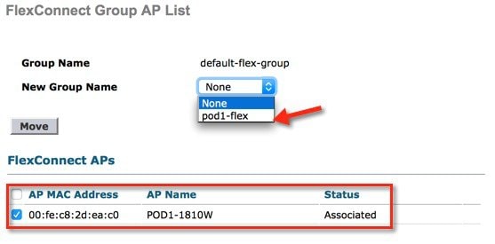
Upgrade or Downgrade behavior
Upon downgrading from release 8.3 to a lower version, the controller will retain the default-flex-group configuration. This group will be treated as any other admin-configurable FlexConnect group, i.e deletion and addition is possible, APs can be manually added or deleted from the group and the maximum limit on number of APs is applicable. Since the support for default-flex-group feature does not exist in earlier releases, FlexConnect APs will not join this group by default.
Upon upgrade to release 8.3 any FlexConnect AP that is not part of a FlexConnect group will join the default-flex-group and get the related default configuration. The rules of inheritance will continue to apply and therefore any AP specific FlexConnect Configuration will not be overwrited by the default FlexConnect group config.
CLI Commands
- The existing show command would display the configuration of the default-flex-group and the APs that are part of it.
- For all the APs that are part of this default group, the “show ap config general <apname>” command would reflect the default FlexConnect Group as shown below
Web Links
- Cisco WLAN Controller Information: http://www.cisco.com/c/en/us/products/wireless/4400-series-wireless-lan-controllers/index.html http://www.cisco.com/c/en/us/products/wireless/2000-series-wireless-lan-controllers/index.html
- Cisco NCS Management Software Information: http://www.cisco.com/c/en/us/products/wireless/prime-network-control-system-series-appliances/index.html
- Cisco MSE Information: http://www.cisco.com/c/en/us/products/wireless/mobility-services-engine/index.html
- Cisco LAP Documentation: http://www.cisco.com/c/en/us/products/wireless/aironet-3500-series/index.html
Terminology
- APM—AP Manager Interface
- Dyn—Dynamic Interface
- Management—Management Interface
- Port—Physical Gbps port
- WiSM-2—Wireless Service Module
- AP—Access Point
- LAG—Link Aggregation
- SPAN—Switch Port Analyzer
- RSPAN—Remote SPAN
- VACL—VLAN Access Control List
- DEC—Distributed Etherchannel
- DFC—Distributed Forwarding Card
- OIR—Online Insertion and Removal
- VSL—Virtual Switch Link
- ISSU—In Service Software Upgrade
- MEC—Multichassis Ether Channel
- VSS—Virtual Switch System
- WCS—Wireless Control System
- NAM—Network Analysis Module
- IDSM—Intrusion Detection Service Module
- FWSM—Firewall Service Module
- STP—Spanning Tree Protocol
- VLAN—Virtual LAN
- SSO—Stateful Switchover
- WCP—Wireless Control Protocol
- WiSM-2—Wireless Service Module-2
FAQ
Q. If I configure LAPs at a remote location as FlexConnect, can I give those LAPs a primary and secondary controller?
Example: There is a primary controller at site A and a secondary controller at site B. If the controller at site A fails, the LAP does failover to the controller at site B. If both controllers are unavailable does the LAP fall into FlexConnect standalone mode?
Yes. First the LAP fails over to its secondary. All WLANs that are locally switched have no changes, and all that are centrally switched just have the traffic go to the new controller. And, if the secondary fails, all WLANs that are marked for local switching (and open/pre-shared key authentication/you are doing AP authenticator) remain up.
Q. How do access points configured in Local mode deal with WLANs configured with FlexConnect Local Switching?
Local mode access points treat these WLANs as normal WLANs. Authentication and data traffic are tunneled back to the WLC. During a WAN link failure this WLAN is completely down and no clients are active on this WLAN until the connection to the WLC is restored.
Q. Can I do web authentication with Local switching?
Yes, you can have an SSID with web-authentication enabled and drop the traffic locally after web-authentication. Web-authentication with Local switching works fine.
Q. Can I use my Guest-Portal on the Controller for an SSID, which is handled locally by the H REAP? If yes, what happens if I lose connectivity to the controller? Do current clients drop immediately?
Yes. Since this WLAN is locally switched, the WLAN is available but no new clients are able to authenticate as the web page is not available. But, the existing clients are not dropped off.
Q. Can FlexConnect certify PCI compliance?
Yes. FlexConnect solution supports rogue detection to satisfy PCI compliance.
Cisco Support Community - Featured Conversations
Cisco Support Community is a forum for you to ask and answer questions, share suggestions, and collaborate with your peers. Below are just some of the most recent and relevant conversations happening right now.
Related Information
- HREAP Design and Deployment Guide
- Cisco 4400 Series Wireless LAN Controllers
- Cisco 2000 Series Wireless LAN Controllers
- Cisco Wireless Control System
- Cisco 3300 Series Mobility Services Engine
- Cisco Aironet 3500 Series
- Cisco Secure Access Control System
- Technical Support & Documentation - Cisco Systems
Contact Cisco
- Open a Support Case

- (Requires a Cisco Service Contract)
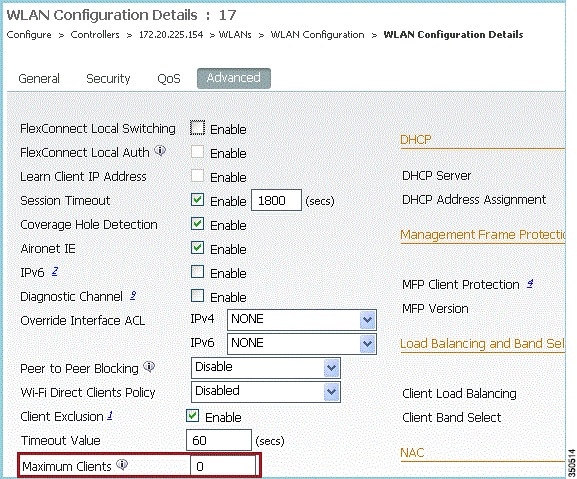

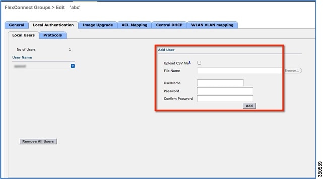
 Feedback