- Preface
- Chapter 1 - Overview
- Chapter 2 - Adding and Deleting Location Servers
- Chapter 3 - Synchronizing Location Servers with Cisco Wireless LAN Controllers and Cisco WCS
- Chapter 4 - Editing Location Server Properties
- Chapter 5 - Managing Location Server Users and Groups
- Chapter 6 - Configuring Event Notifications
- Chapter 7 - Location Planning and Verification
- Chapter 8 - Monitoring Location Servers and Site
- Chapter 9 - Performing Maintenance Operations
- Index
Location Planning and Verification
This chapter describes how to plan access point deployment based on applications employed.
You can check the ability of an existing access point deployment to estimate the true location of an element within 10 meters at least 90% of the time using a location readiness calculation based on the number and placement of access points.
Details on using calibration data to examine location quality, as an alternative to using the location readiness calculation, are also described.
Additionally, details on analyzing the location accuracy of non-rogue and rogue clients and asset tags using testpoints on an area or floor map; and, using chokepoints to enhance location accuracy for tags are described.
This chapter contains the following sections:
•![]() "Deployment Planning for Data, Voice, and Location" section
"Deployment Planning for Data, Voice, and Location" section
•![]() "Inspecting Location Readiness and Quality" section
"Inspecting Location Readiness and Quality" section
•![]() "Analyzing Element Location Accuracy Using Testpoints" section
"Analyzing Element Location Accuracy Using Testpoints" section
•![]() "Using Chokepoints to Enhance Tag Location Reporting" section
"Using Chokepoints to Enhance Tag Location Reporting" section
Deployment Planning for Data, Voice, and Location
You can calculate the recommended number and location of access points based on whether data and/or voice traffic and/or location will be active.
To calculate recommended number and placement of access points for a given deployment, follow these steps:
Step 1 ![]() In Cisco WCS, choose Monitor > Maps.
In Cisco WCS, choose Monitor > Maps.
Step 2 ![]() Click on the appropriate location link from the list that displays.
Click on the appropriate location link from the list that displays.
A map appears showing placement of all installed elements (access points, clients, tags) and their relative signal strength.
Step 3 ![]() Select Planning Mode from the menu found at the top-right of the window. Click GO.
Select Planning Mode from the menu found at the top-right of the window. Click GO.
A color-coded map summarizing contributing access points appears.
Step 4 ![]() Click Add APs to open a window to enter data necessary to calculate the recommended number of access points.
Click Add APs to open a window to enter data necessary to calculate the recommended number of access points.
Step 5 ![]() In the window that appears, drag the dashed rectangle over the map location for which you want to calculate the recommended access points.
In the window that appears, drag the dashed rectangle over the map location for which you want to calculate the recommended access points.

Note ![]() Adjust the size or placement of the rectangle by selecting the edge of the rectangle and holding down the Ctrl key. Move the mouse as necessary to outline the targeted location.
Adjust the size or placement of the rectangle by selecting the edge of the rectangle and holding down the Ctrl key. Move the mouse as necessary to outline the targeted location.
Step 6 ![]() Check the check box next to the service that will be used on the floor. Options are Data/Coverage (default), Voice and Location. Click Calculate.
Check the check box next to the service that will be used on the floor. Options are Data/Coverage (default), Voice and Location. Click Calculate.
The recommended number of access points given the services requested appears.

Note ![]() Each service option is inclusive of all services that are listed above it. For example, if you check the Location box, the calculation will consider data/coverage, voice and location in determining the optimum number of access points required.
Each service option is inclusive of all services that are listed above it. For example, if you check the Location box, the calculation will consider data/coverage, voice and location in determining the optimum number of access points required.

Note ![]() Recommended calculations assume the need for consistently strong signals. In some cases, fewer access points may be required than recommended.
Recommended calculations assume the need for consistently strong signals. In some cases, fewer access points may be required than recommended.
Step 7 ![]() Click Apply to generate a map based on the recommendations to see recommended placement of the access points in the selected area.
Click Apply to generate a map based on the recommendations to see recommended placement of the access points in the selected area.

Note ![]() Check the Location services option to ensure that the recommended access points will provide the true location of an element within 10 meters at least 90% of the time.
Check the Location services option to ensure that the recommended access points will provide the true location of an element within 10 meters at least 90% of the time.
Inspecting Location Readiness and Quality
You can configure Cisco WCS to verify the ability of the existing access point deployment to estimate the true location of an element within 10 meters at least 90% of the time. The location readiness calculation is based on the number and placement of access points.
You can also check the location quality and the ability of a given location to meet the location specification (10 m, 90%) based on data points gathered during a physical inspection and calibration.
Inspecting Location Readiness Using Access Point Data
To inspect location readiness using access point data, follow these steps:
Step 1 ![]() In Cisco WCS, choose Monitor > Maps.
In Cisco WCS, choose Monitor > Maps.
Step 2 ![]() Click on the appropriate floor location link from the list that displays.
Click on the appropriate floor location link from the list that displays.
A map displays showing placement of all installed elements (access points, clients, tags) and their relative signal strength.

Note ![]() If RSSI is not displayed, you can enable AP Heatmaps under the Layer menu (top-left).
If RSSI is not displayed, you can enable AP Heatmaps under the Layer menu (top-left).
Step 3 ![]() Select Inspect Location Readiness from the Select a command menu found at the top-right of the window. Click GO.
Select Inspect Location Readiness from the Select a command menu found at the top-right of the window. Click GO.
A color-coded map appears showing those areas that do (Yes) and do not (No) meet the 10 meter, 90% location specification.
Inspecting Location Quality Using Calibration Data
After completing a calibration model based on data points generated during a physical tour of the area, you can inspect the location quality of the access points. To inspect location quality based on calibration, follow these steps:
Step 1 ![]() In Cisco WCS, choose Monitor > Maps.
In Cisco WCS, choose Monitor > Maps.
Step 2 ![]() Choose RF Calibration Model from the menu found at the top-right of the window. Click GO.
Choose RF Calibration Model from the menu found at the top-right of the window. Click GO.
A list of calibration models appears.
Step 3 ![]() Click the appropriate calibration model.
Click the appropriate calibration model.
Details on the calibration including date of last calibration, number of data points by signal type (802.11a, 802.11 b/g) used in the calibration, location, and coverage are displayed.
Step 4 ![]() At the same window, click the Inspect Location Quality link found under the Calibration Floors heading.
At the same window, click the Inspect Location Quality link found under the Calibration Floors heading.
A color-coded map noting percentage of location errors appears.

Note ![]() You can modify the distance selected to see the effect on the location errors.
You can modify the distance selected to see the effect on the location errors.
Analyzing Element Location Accuracy Using Testpoints
You can analyze the location accuracy of non-rogue and rogue clients and asset tags by entering testpoints on an area or floor map. You can use this feature to validate location information generated either automatically by access points or manually by calibration.

Note ![]() By checking for location accuracy, you are checking the ability of the existing access point deployment to estimate the true location of an element within 10 meters at least 90% of the time.
By checking for location accuracy, you are checking the ability of the existing access point deployment to estimate the true location of an element within 10 meters at least 90% of the time.

Note ![]() Before starting this process, be sure to have the MAC addresses and locations for all elements within the area or floor to be analyzed. You need this information when placing the testpoints on the map. If analyzing location after calibration, you should analyze the location accuracy of at least as many elements entered during calibration.
Before starting this process, be sure to have the MAC addresses and locations for all elements within the area or floor to be analyzed. You need this information when placing the testpoints on the map. If analyzing location after calibration, you should analyze the location accuracy of at least as many elements entered during calibration.

Note![]() •
•![]() The Advanced Debug option must be enabled in Cisco WCS to allow use of the location accuracy testpoint feature.
The Advanced Debug option must be enabled in Cisco WCS to allow use of the location accuracy testpoint feature.
•![]() For releases 3.0 and 2.1, you must enable the Advanced Debug option at both the location appliance and Cisco WCS level. Refer to the appropriate Cisco Location Appliance Configuration Guide at the following URL for more details:
For releases 3.0 and 2.1, you must enable the Advanced Debug option at both the location appliance and Cisco WCS level. Refer to the appropriate Cisco Location Appliance Configuration Guide at the following URL for more details:
http://www.cisco.com/en/US/products/ps6386/products_installation_and_configuration_guides_list.html
To enable the advanced debug option and to assign testpoints to a floor map to check location accuracy, follow these steps:
Step 1 ![]() In Cisco WCS, choose Monitor > Maps (Figure 7-1).
In Cisco WCS, choose Monitor > Maps (Figure 7-1).
Figure 7-1 Monitor > Maps Window
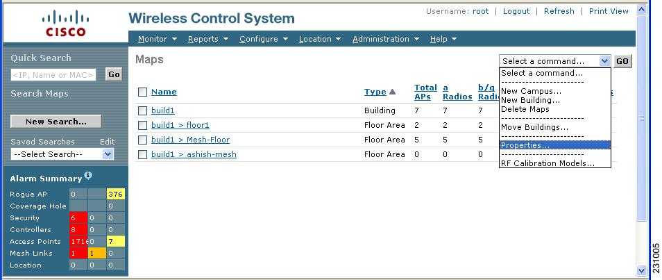
Step 2 ![]() Select Properties from the Select a command drop-down menu. Click GO.
Select Properties from the Select a command drop-down menu. Click GO.
The Maps > Properties window appears (Figure 7-2).
Figure 7-2 Maps > Properties Window
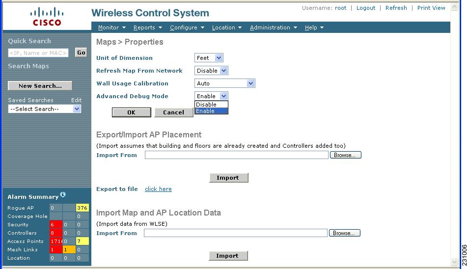
Step 3 ![]() Select Enable from the Advanced Debug drop-down menu. Click OK.
Select Enable from the Advanced Debug drop-down menu. Click OK.
You are returned to the Maps summary window. You are now ready to assign testpoints to a selected area or map.
Step 4 ![]() Choose Monitor > Maps. Select the area or floor you want to analyze from the map summary that appears.
Choose Monitor > Maps. Select the area or floor you want to analyze from the map summary that appears.
The selected area or floor appears (Figure 7-3).
Figure 7-3 Selected Area or Floor Map Chosen at Monitor > Maps Window
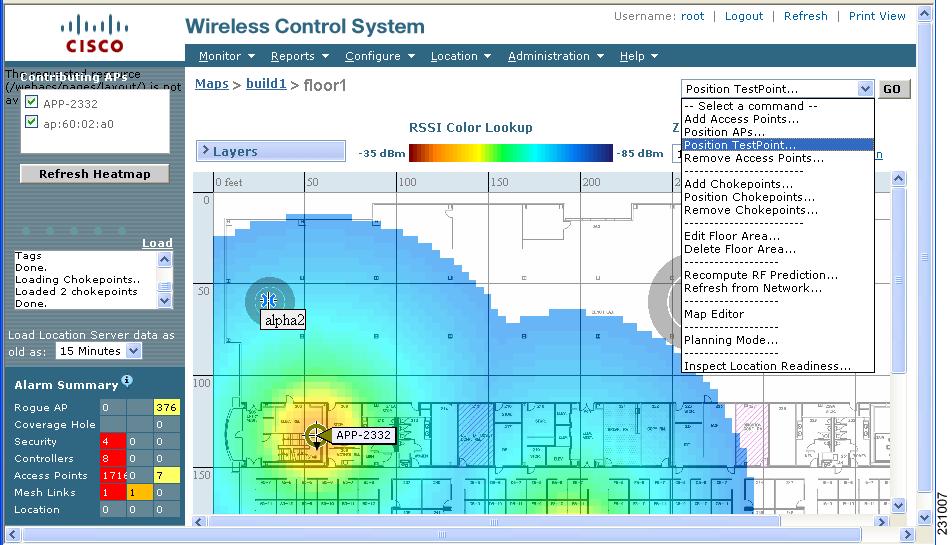
Step 5 ![]() Select Position TestPoint from the Select a command drop-down menu (top-right). Click GO.
Select Position TestPoint from the Select a command drop-down menu (top-right). Click GO.
A blank map of the selected area or floor appears for testpoint assignment (Figure 7-4).
Figure 7-4 Position TestPoint Assignment Window
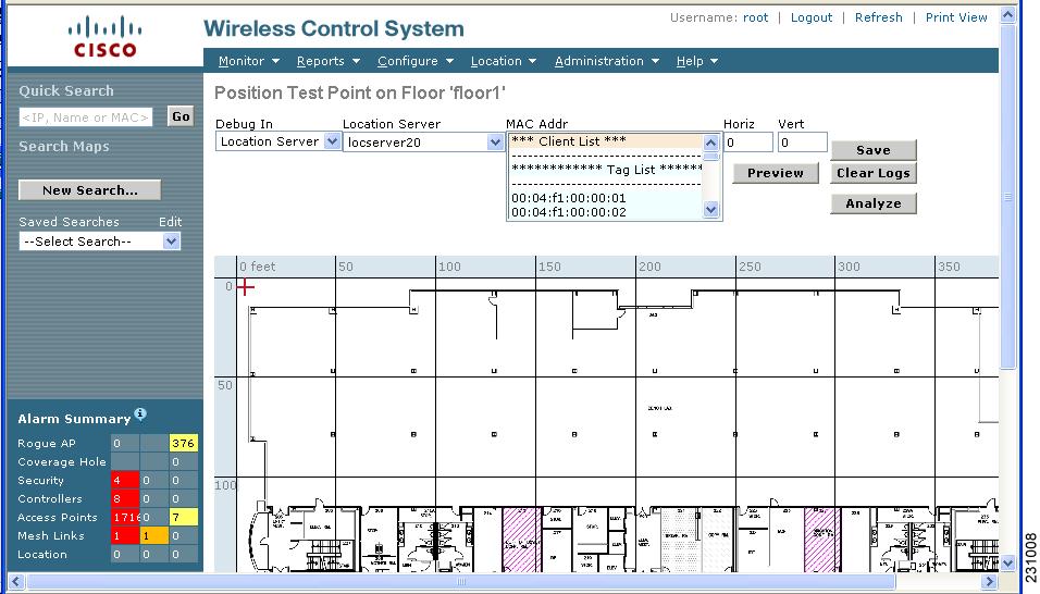
Step 6 ![]() Move the red cross hair cursor (top-left) to the map location that corresponds to the element.
Move the red cross hair cursor (top-left) to the map location that corresponds to the element.

Note ![]() Instead of using the cursor, you can enter the horizontal (Horz) and vertical (Vert) coordinates of the asset tag or client to mark its location.
Instead of using the cursor, you can enter the horizontal (Horz) and vertical (Vert) coordinates of the asset tag or client to mark its location.
Step 7 ![]() Select the MAC Address (MAC Addr) associated with that element from the drop-down menu. Click Preview to verify location. Click Save to finalize placement.
Select the MAC Address (MAC Addr) associated with that element from the drop-down menu. Click Preview to verify location. Click Save to finalize placement.
Step 8 ![]() Click Stop after approximately two minutes to end collection of data. This period is recommended to provide enough data.
Click Stop after approximately two minutes to end collection of data. This period is recommended to provide enough data.
A pop up box appears confirming addition of the testpoint.
The red cross hair cursor returns to the upper left hand corner after placement is confirmed. You are ready to mark additional testpoints.

Note ![]() If you do not click Stop, data is collected until the location server restarts or until you click Clear Logs. Additionally, for the highest accuracy it is highly recommended that you stop collection of data of one testpoint before placing another testpoint on the map.
If you do not click Stop, data is collected until the location server restarts or until you click Clear Logs. Additionally, for the highest accuracy it is highly recommended that you stop collection of data of one testpoint before placing another testpoint on the map.
Step 9 ![]() Repeat steps 6 and 7 for each client or asset tag testpoint you want to add to the map.
Repeat steps 6 and 7 for each client or asset tag testpoint you want to add to the map.
Step 10 ![]() Click Analyze to determine location accuracy of the entered testpoints.
Click Analyze to determine location accuracy of the entered testpoints.
A pop up window appears providing accuracy information.
Using Chokepoints to Enhance Tag Location Reporting
Installing chokepoints provides enhanced location information for active RFID tags. When an active CCX version 1 compliant RFID tag enters the range of a chokepoint, it is stimulated by the chokepoint. The MAC address of this chokepoint is then included in the next beacon sent by the stimulated tag. All access points that detect this tag beacon then forward the information to the controller and location appliance.
Using chokepoints in conjunction with active CCX compliant tags provides immediate location information on a tag and its asset. When a CCX tag moves out of the range of a chokepoint, its subsequent beacon frames do not contain any identifying chokepoint information. Location determination of the tag defaults to the standard calculation methods based on RSSIs reported by access point associated with the tag.
Adding Chokepoints to the WCS Database and Map
Chokepoints are installed and configured as recommended by the Chokepoint vendor. When the chokepoint is installed and operational, you can add the chokepoint to the location database and positioned on a Cisco WCS map.

Note ![]() Chokepoints are managed by the chokepoint vendor's application.
Chokepoints are managed by the chokepoint vendor's application.
To add a chokepoint to the WCS database and appropriate map, follow these steps:
Step 1 ![]() Choose Configure > Chokepoints from the main menu (top).
Choose Configure > Chokepoints from the main menu (top).
The All Chokepoints summary window appears (Figure 7-5).
Figure 7-5 All Chokepoints Summary Window
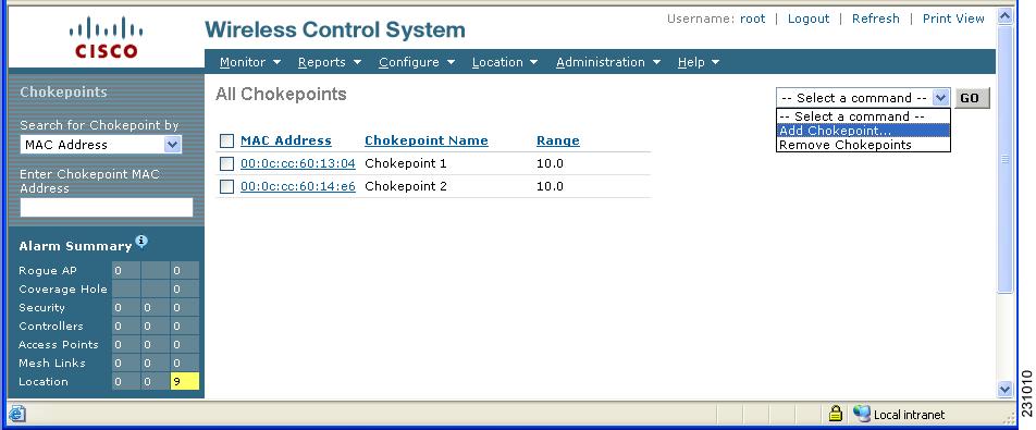
Step 2 ![]() Select Add Chokepoint from the Select a command menu (Figure 7-6). Click GO.
Select Add Chokepoint from the Select a command menu (Figure 7-6). Click GO.
The Add Chokepoint entry screen appears.
Figure 7-6 Add Chokepoint Window
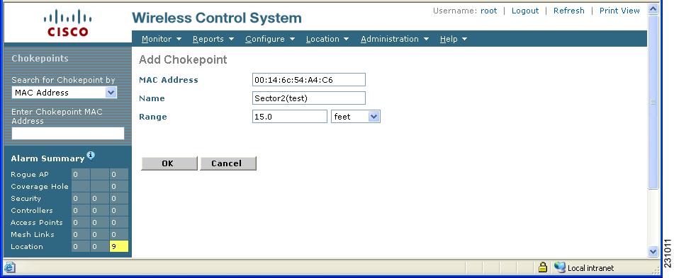
Step 3 ![]() Enter the MAC address, name, and coverage range for the chokepoint.
Enter the MAC address, name, and coverage range for the chokepoint.

Note ![]() The chokepoint range is product-specific and is supplied by the chokepoint vendor.
The chokepoint range is product-specific and is supplied by the chokepoint vendor.
Step 4 ![]() Click OK to save the chokepoint entry to the database.
Click OK to save the chokepoint entry to the database.
The All Chokepoints summary window appears with the new chokepoint entry listed (Figure 7-7).
Figure 7-7 All Chokepoints Summary Window
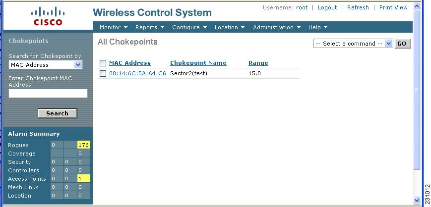

Note ![]() After you add the chokepoint to the database, you can place the chokepoint on the appropriate WCS floor map.
After you add the chokepoint to the database, you can place the chokepoint on the appropriate WCS floor map.
Step 5 ![]() To add the chokepoint to a map, choose Monitor > Maps (Figure 7-8).
To add the chokepoint to a map, choose Monitor > Maps (Figure 7-8).
Figure 7-8 Monitor > Maps Window
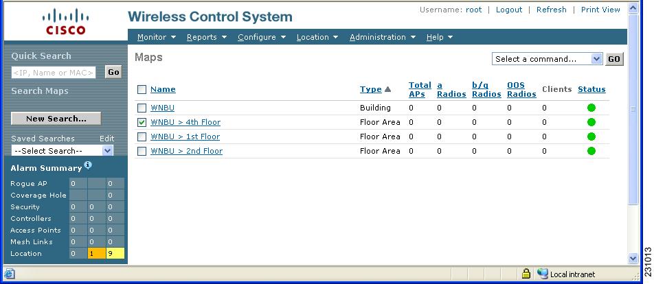
Step 6 ![]() At the Maps window, select the link that corresponds to the floor location of the chokepoint. The floor map appears (Figure 7-9).
At the Maps window, select the link that corresponds to the floor location of the chokepoint. The floor map appears (Figure 7-9).
Figure 7-9 Selected Floor Map
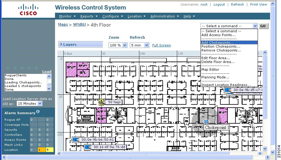
Step 7 ![]() Select Add Chokepoints from the Select a command menu. Click GO.
Select Add Chokepoints from the Select a command menu. Click GO.
The Add Chokepoints summary window appears (Figure 7-10).

Note ![]() The Add Chokepoints summary window lists all recently-added chokepoints that are in the database but not yet mapped.
The Add Chokepoints summary window lists all recently-added chokepoints that are in the database but not yet mapped.
Figure 7-10 Add Chokepoints Summary Window
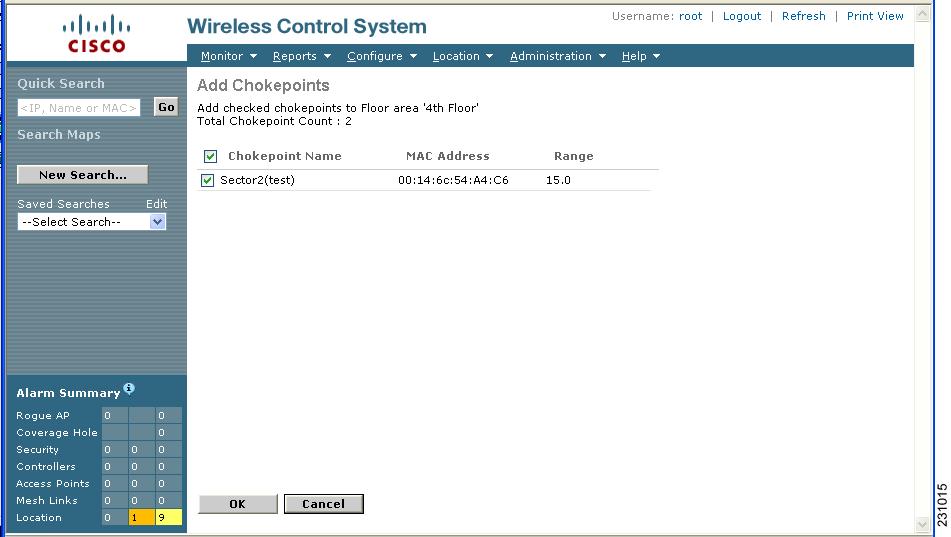
Step 8 ![]() Check the box next to the chokepoint to be added to the map. Click OK.
Check the box next to the chokepoint to be added to the map. Click OK.
A map appears with a chokepoint icon located in the top-left hand corner (Figure 7-11). You are now ready to place the chokepoint on the map.
Figure 7-11 Map for Positioning Chokepoint
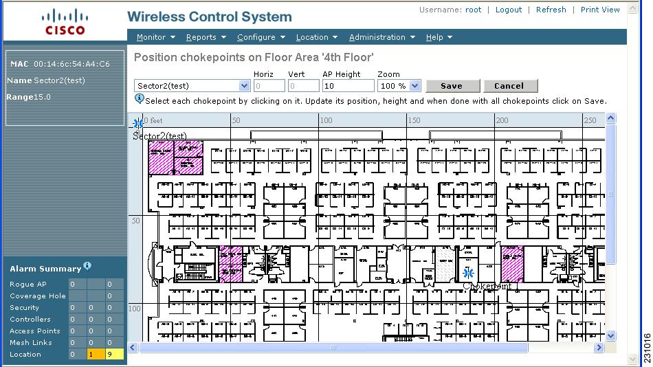
Step 9 ![]() Left click on the chokepoint icon and drag and place it in the proper location (Figure 7-12).
Left click on the chokepoint icon and drag and place it in the proper location (Figure 7-12).
Figure 7-12 Chokepoint Icon is Positioned on the Floor Map
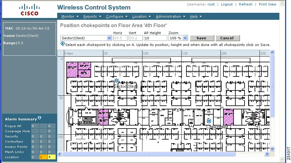

Note ![]() The MAC address, name, and coverage range of the chokepoint appear in the left panel when you click on the chokepoint icon for placement.
The MAC address, name, and coverage range of the chokepoint appear in the left panel when you click on the chokepoint icon for placement.
Step 10 ![]() Click Save when icon is correctly placed on the map.
Click Save when icon is correctly placed on the map.
You are returned to the floor map and the added chokepoint appears on the map (Figure 7-13).

Note ![]() The icon for the newly added chokepoint may or may not appear on the map depending on the display settings for that floor. If the icon did not appear, proceed with Step 11.
The icon for the newly added chokepoint may or may not appear on the map depending on the display settings for that floor. If the icon did not appear, proceed with Step 11.
Figure 7-13 New Chokepoint Displayed on Floor Map
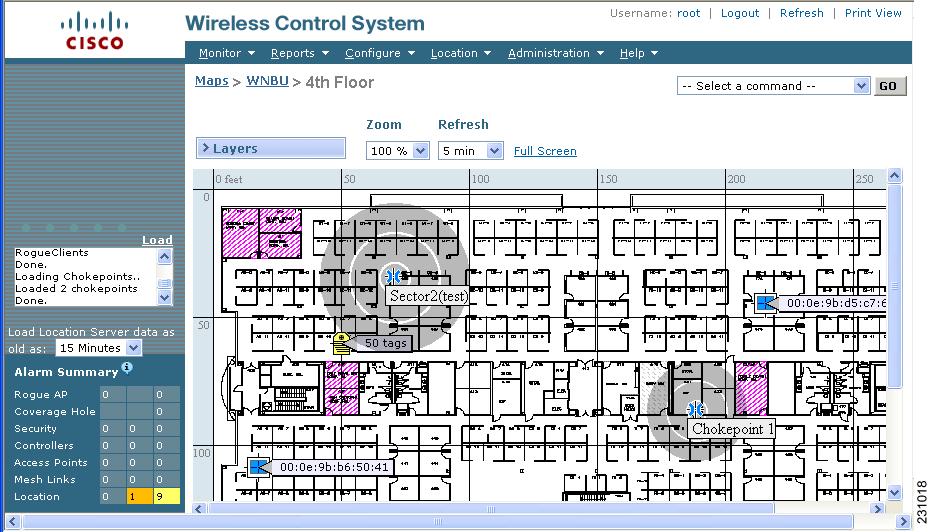

Note ![]() The rings around the chokepoint icon indicate the coverage area. When a CCX tag and its asset passes within the coverage area, location details are broadcast and the tag is automatically mapped on the chokepoint coverage circle. When the tag moves out of the chokepoint range, its location is calculated as before and it is no longer mapped on the chokepoint rings. In Figure 7-13, the tag is currently out of range of the chokepoint.
The rings around the chokepoint icon indicate the coverage area. When a CCX tag and its asset passes within the coverage area, location details are broadcast and the tag is automatically mapped on the chokepoint coverage circle. When the tag moves out of the chokepoint range, its location is calculated as before and it is no longer mapped on the chokepoint rings. In Figure 7-13, the tag is currently out of range of the chokepoint.

Note ![]() MAC address, name, and range of a chokepoint display when you pass a mouse over its map icon
MAC address, name, and range of a chokepoint display when you pass a mouse over its map icon
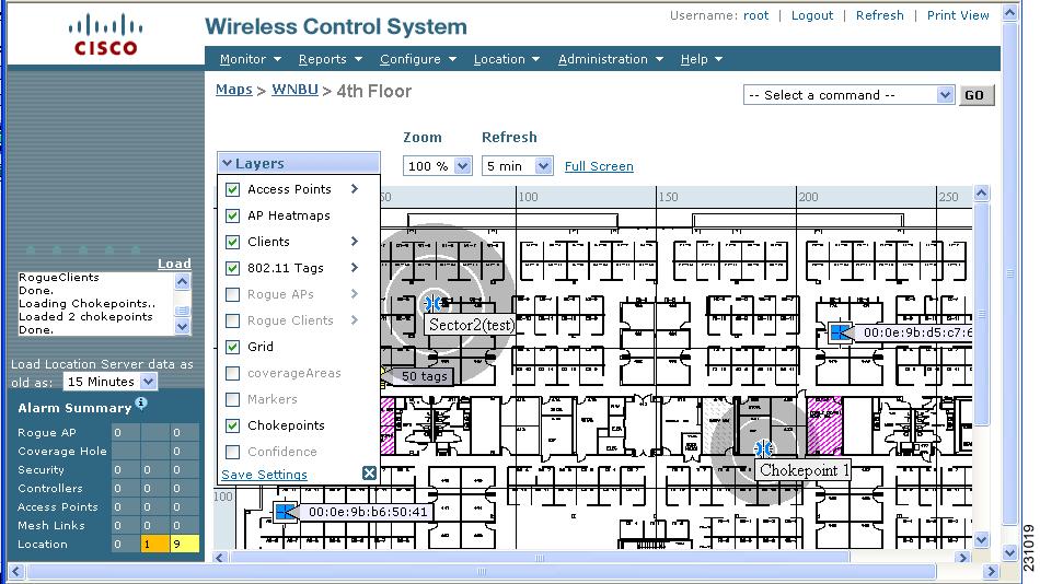
Step 11 ![]() If the chokepoint does not appear on the map, click Layers to collapse a selection menu of possible elements to display on the map. Click the Chokepoints check box.
If the chokepoint does not appear on the map, click Layers to collapse a selection menu of possible elements to display on the map. Click the Chokepoints check box.
The chokepoint appears on the map (Figure 7-14).
Figure 7-14 Chokepoints Displayed on Map
Step 12 ![]() Click X to close the Layers window.
Click X to close the Layers window.

Note ![]() Do not select Save Settings unless you want to save this display criteria for all maps.
Do not select Save Settings unless you want to save this display criteria for all maps.
Removing Chokepoints from the WCS Database and Map
You can remove one or multiple chokepoints at a time.
Follow these steps to delete a chokepoint.
Step 1 ![]() Choose Configure > Chokepoints. The All Chokepoints window appears.
Choose Configure > Chokepoints. The All Chokepoints window appears.
Step 2 ![]() Check the box(es) next to the chokepoint(s) to be deleted.
Check the box(es) next to the chokepoint(s) to be deleted.
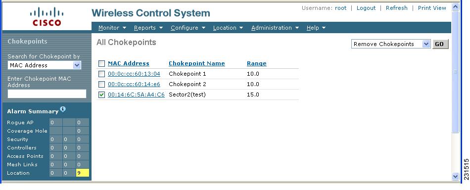
Step 3 ![]() Select Remove Chokepoints from the Select a command drop-down menu. Click GO (Figure 7-15).
Select Remove Chokepoints from the Select a command drop-down menu. Click GO (Figure 7-15).
Figure 7-15 Removing a Chokepoint
Step 4 ![]() To confirm chokepoint deletion, click OK in the pop-up window that appears.
To confirm chokepoint deletion, click OK in the pop-up window that appears.
You are returned to the All Chokepoints window. A message confirming deletion of the chokepoint appears. The deleted chokepoint(s) is no longer listed in the window.
 Feedback