- Supported Hardware
- Required Tools and Information
- Hardware Specifications
- Choosing a Physical Location for the Cisco Prime Network Control System Appliance
- Unpacking the Cisco Prime Network Control System Appliance
- Mounting the Cisco Prime Network Control System Appliance in a Rack
- Front and Rear Panel
Installation and Initial Configuration
This chapter describes how to initially install and configure your Cisco Prime Network Control System (NCS) appliance.
This chapter contains the following sections:
•![]() Required Tools and Information
Required Tools and Information
•![]() Choosing a Physical Location for the Cisco Prime Network Control System Appliance
Choosing a Physical Location for the Cisco Prime Network Control System Appliance
•![]() Unpacking the Cisco Prime Network Control System Appliance
Unpacking the Cisco Prime Network Control System Appliance
•![]() Mounting the Cisco Prime Network Control System Appliance in a Rack
Mounting the Cisco Prime Network Control System Appliance in a Rack
•![]() Replacing a Failed Hot-Swap Hard Disk Drive
Replacing a Failed Hot-Swap Hard Disk Drive
•![]() Replacing a Hot-Swap AC Power Supply
Replacing a Hot-Swap AC Power Supply
•![]() Connecting and Using the CLI Console
Connecting and Using the CLI Console
•![]() Powering On the Cisco Prime Network Control System Appliance
Powering On the Cisco Prime Network Control System Appliance
•![]() Configuring the Cisco Prime Network Control System Appliance
Configuring the Cisco Prime Network Control System Appliance
•![]() Logging in to the NCS Appliance
Logging in to the NCS Appliance
•![]() Exporting Data from the Cisco Wireless Controller System
Exporting Data from the Cisco Wireless Controller System
•![]() Importing WCS data to the Cisco Prime Network Control System
Importing WCS data to the Cisco Prime Network Control System
•![]() Verifying the Cisco Prime Network Control System Appliance Software State
Verifying the Cisco Prime Network Control System Appliance Software State
•![]() Manually Stopping Cisco Prime Network Control System Appliance Software
Manually Stopping Cisco Prime Network Control System Appliance Software

Note ![]() For configuration details beyond initial installation, refer to the Cisco Prime Network Control System Configuration Guide at the following URL:
For configuration details beyond initial installation, refer to the Cisco Prime Network Control System Configuration Guide at the following URL:
http://www.cisco.com/en/US/products/ps11686/tsd_products_support_series_home.html
Supported Hardware
NCS software is packaged with your physical appliance, or can be downloaded as an image for installation, or can be downloaded as a software image to run as a virtual appliance on a customer-supplied server. The NCS virtual appliance can be deployed on any of the platforms listed in Table 1-1.
Required Tools and Information
This section lists the required hardware and other information that you need to install and setup the NCS appliance.
Required Hardware
You need the following equipment to install an NCS appliance in an Electronics Industries Alliance (EIA) rack:
•![]() A Cisco Prime Network Control System appliance
A Cisco Prime Network Control System appliance
•![]() Network cables
Network cables
•![]() One rack unit (RU) free space in an EIA-standard rack
One rack unit (RU) free space in an EIA-standard rack
•![]() Rack mounting kit (included with the Cisco Prime Network Control System appliance shipment)
Rack mounting kit (included with the Cisco Prime Network Control System appliance shipment)
•![]() A serial console cable
A serial console cable

Note ![]() If you are installing this unit in a threaded-hole rack, you must supply screws that fit the threaded-hole rack and the appropriate screwdriver or Torx driver for those screws.
If you are installing this unit in a threaded-hole rack, you must supply screws that fit the threaded-hole rack and the appropriate screwdriver or Torx driver for those screws.
CLI Console Requirements
You need an ANSI or VT-100 terminal emulator application on a laptop, desktop, or palmtop to connect to the NCS appliance console.
System Configuration Parameters
Obtain the following parameters from your network administrator:
•![]() A hostname for the NCS appliance
A hostname for the NCS appliance
•![]() An IP address for the NCS appliance
An IP address for the NCS appliance
•![]() A default net mask for the IP address
A default net mask for the IP address
•![]() An IP address for the default gateway
An IP address for the default gateway
•![]() A default DNS domain
A default DNS domain
•![]() An IP address for the primary name server
An IP address for the primary name server
•![]() A primary NTP server
A primary NTP server
Hardware Specifications
Table 1-2 lists the hardware specifications of the NCS appliance.
Choosing a Physical Location for the Cisco Prime Network Control System Appliance
For maximum safety and reliability, mount the NCS appliance using the following guidelines.
General Precautions
To reduce the risk of personal injury or damage to the NCS appliance, observe the following precautions:
•![]() Place the product away from radiators, heat registers, stoves, amplifiers, or other products that produce heat.
Place the product away from radiators, heat registers, stoves, amplifiers, or other products that produce heat.
•![]() Never use the product in a wet location.
Never use the product in a wet location.
•![]() Avoid inserting foreign objects through openings in the product.
Avoid inserting foreign objects through openings in the product.
•![]() To reduce risk of injury from electric shock hazards, do not open the product enclosure.
To reduce risk of injury from electric shock hazards, do not open the product enclosure.
Laser Devices
Laser devices are used within the DVD of the NCS appliance. The DVD has no defined use at the customer site.
To reduce the risk of exposure to hazardous radiation, observe the following precautions:
•![]() Do not try to open the laser device enclosure. There are no user-serviceable components inside.
Do not try to open the laser device enclosure. There are no user-serviceable components inside.
•![]() Do not operate controls, make adjustments, or perform procedures to the laser device other than those specified herein.
Do not operate controls, make adjustments, or perform procedures to the laser device other than those specified herein.
•![]() Allow only Cisco authorized service technicians to repair the laser device.
Allow only Cisco authorized service technicians to repair the laser device.
Space and Airflow Requirements
Install the NCS appliance in an EIA-standard rack. One rack unit is required for each NCS appliance.
Ensure that you can reach the NCS appliance and all cables.
•![]() Ensure that the NCS appliance is within 328 ft (100 m) equivalent distance from any equipment connected to the 10/100/1000BASE-T ports.
Ensure that the NCS appliance is within 328 ft (100 m) equivalent distance from any equipment connected to the 10/100/1000BASE-T ports.
•![]() Ensure that the power cord can reach a 110 or 220 VAC grounded electrical outlet.
Ensure that the power cord can reach a 110 or 220 VAC grounded electrical outlet.
Ensure that there is sufficient room at the back of the NCS appliance for all cables and connectors.
•![]() Leave a minimum clearance of 63.5 cm (25 in.) in front of the rack.
Leave a minimum clearance of 63.5 cm (25 in.) in front of the rack.
•![]() Leave a minimum clearance of 76.2 cm (30 in.) behind the rack.
Leave a minimum clearance of 76.2 cm (30 in.) behind the rack.
•![]() Leave a minimum clearance of 121.9 cm (48 in.) from the back of the rack to the back of another rack or row of racks.
Leave a minimum clearance of 121.9 cm (48 in.) from the back of the rack to the back of another rack or row of racks.


Temperature Requirements
To ensure continued safe and reliable equipment operation, install or position the system in a well ventilated, climate-controlled environment.
Ensure that the ambient operating temperature remains between 10 and 35° C (50 and 95° F), taking into account the elevated temperatures that occur when equipment is installed in a rack.

Power Requirements
Installation of this equipment must comply with local and regional electrical regulations governing the installation of information technology equipment by licensed electricians. This equipment is designed to operate in installations covered by NFPA 70, 1999 Edition (National Electric Code) and NFPA 75, 1992 (code for Protection of Electronic Computer/Data Processing Equipment). For electrical power ratings on options, refer to the product rating label or the user documentation supplied with that option.

Power Supplies on the Cisco Prime Network Control System Appliance
The NCS appliance has two power supplies.
 |
Warning |

Batteries
The NCS appliance might include a real-time clock battery or coin cell battery that might contain perchlorate and might require special handling when recycled or disposed of in California.
Refer to the following link for disposal information.
http://www.dtsc.ca.gov/hazardouswaste/perchlorate

Electrical Grounding Requirements
The NCS appliance must be grounded properly for proper operation and safety. In the United States, you must install the equipment in accordance with NFPA 70, 1999 Edition (National Electric Code), Article 250, as well as any local and regional building codes. In Canada, you must install the equipment in accordance with Canadian Standards Association, CSA C22.1, Canadian Electrical Code. In all other countries, you must install the equipment in accordance with any regional or national electrical wiring codes, such as the International Electrotechnical Commission (IEC) Code 364, parts 1 through 7.
Furthermore, you must verify that all power distribution devices used in the installation, such as branch wiring and receptacles, are listed or certified grounding-type devices. Because of the high ground-leakage currents associated with multiple systems connected to the same power source, Cisco recommends the use of a PDU that is either permanently wired to the building's branch circuit or includes a nondetachable cord that is wired to an industrial-style plug. NEMA locking-style plugs or those complying with IEC 60309 are considered suitable for this purpose. Using common power outlet strips for the NCS appliance is not recommended.
Rack Warnings


Unpacking the Cisco Prime Network Control System Appliance
Follow these steps to unpack the NCS appliance.
Step 1 ![]() Open the shipping container and carefully remove the contents.
Open the shipping container and carefully remove the contents.
Step 2 ![]() Return all packing materials to the shipping container and save it.
Return all packing materials to the shipping container and save it.
Step 3 ![]() Ensure that all items listed in the "Package Contents" section are included in the shipment.
Ensure that all items listed in the "Package Contents" section are included in the shipment.
Step 4 ![]() Check each item for damage. If any item is damaged or missing, notify your authorized Cisco sales representative.
Check each item for damage. If any item is damaged or missing, notify your authorized Cisco sales representative.
Package Contents
Each Cisco Prime Network Control System appliance package contains the following items:
•![]() One Cisco Prime Network Control System appliance
One Cisco Prime Network Control System appliance
•![]() One rack mount kit
One rack mount kit
•![]() Two power cords
Two power cords
Mounting the Cisco Prime Network Control System Appliance in a Rack
 |
Warning |

To reduce the risk of personal injury or damage to the equipment:
•![]() Observe local occupational health and safety requirements and guidelines for manual material handling.
Observe local occupational health and safety requirements and guidelines for manual material handling.
•![]() Getting help to lift and stabilize the NCS appliance during installation or removal is recommended, especially when the system is not fastened to the rails.
Getting help to lift and stabilize the NCS appliance during installation or removal is recommended, especially when the system is not fastened to the rails.
•![]() Use caution when installing the NCS appliance in or removing it from the rack; it is unstable when not fastened to the rails.
Use caution when installing the NCS appliance in or removing it from the rack; it is unstable when not fastened to the rails.
•![]() Always plan the rack installation so that the heaviest item is on the bottom of the rack. Install the heaviest item first and continue to populate the rack from the bottom to the top.
Always plan the rack installation so that the heaviest item is on the bottom of the rack. Install the heaviest item first and continue to populate the rack from the bottom to the top.
The NCS appliance comes with a universal rack mount kit that can be installed in a square-hole rack, round-hole rack, or a threaded-hole rack. You can order replacement universal rack mount kits from Cisco. The replacement part PID is AIR-SRVR-URMK=.

Note ![]() You must provide the threaded-hole screws to secure the mounting rails to the rack. Threaded-hole screws are not shipped with the system.
You must provide the threaded-hole screws to secure the mounting rails to the rack. Threaded-hole screws are not shipped with the system.
Installing the Cisco Prime Network Control System Appliance in the Rack Cabinet Using the Universal Rack Mount Kit
Review the documentation that comes with the rack cabinet for safety and cabling information. Before you install the NCS appliance in a rack cabinet, review the following guidelines:
•![]() Make sure that the room air temperature is below 35° C (95° F).
Make sure that the room air temperature is below 35° C (95° F).
•![]() Do not block any air vents; usually 15 cm (6 in.) of space provides proper airflow.
Do not block any air vents; usually 15 cm (6 in.) of space provides proper airflow.
•![]() Do not leave open spaces above or below an installed NCS appliance in your rack cabinet. To help prevent damage to NCS appliance components, always install a blank filler panel to cover the open space and to help ensure proper air circulation.
Do not leave open spaces above or below an installed NCS appliance in your rack cabinet. To help prevent damage to NCS appliance components, always install a blank filler panel to cover the open space and to help ensure proper air circulation.
•![]() Install the NCS appliance only in a rack cabinet with perforated doors.
Install the NCS appliance only in a rack cabinet with perforated doors.
•![]() Plan the device installation starting from the bottom of the rack cabinet.
Plan the device installation starting from the bottom of the rack cabinet.
•![]() Install the heaviest device in the bottom of the rack cabinet.
Install the heaviest device in the bottom of the rack cabinet.
•![]() Do not extend more than one device out of the rack cabinet at the same time.
Do not extend more than one device out of the rack cabinet at the same time.
•![]() Remove the rack doors and side panels to provide easier access during installation.
Remove the rack doors and side panels to provide easier access during installation.
•![]() Connect the NCS appliance to a properly grounded outlet.
Connect the NCS appliance to a properly grounded outlet.
•![]() Do not overload the power outlet when you install multiple devices in the rack cabinet.
Do not overload the power outlet when you install multiple devices in the rack cabinet.
•![]() Install the NCS appliance in a rack that meets the following requirement:
Install the NCS appliance in a rack that meets the following requirement:
–![]() Minimum depth of 70 mm (2.76 in.) between the front mounting flange and inside of the front door.
Minimum depth of 70 mm (2.76 in.) between the front mounting flange and inside of the front door.


The following illustration shows the items that you need to install the NCS appliance in the rack cabinet. If any items are missing or damaged, contact your place of purchase.

Note ![]() Some items come with the NCS appliance, not in the rack installation kit.
Some items come with the NCS appliance, not in the rack installation kit.
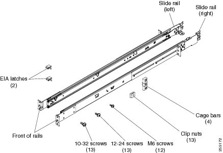

Note ![]() Use cage bars with square-holed racks, clip nuts with round-holed racks, and your own screws or the screws provided in this kit with threaded-hole racks.
Use cage bars with square-holed racks, clip nuts with round-holed racks, and your own screws or the screws provided in this kit with threaded-hole racks.

Note ![]() If the slide rails in your rack installation kit came with shipping thumbscrews, remove them before you begin the following installation procedure.
If the slide rails in your rack installation kit came with shipping thumbscrews, remove them before you begin the following installation procedure.
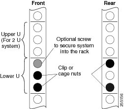
Step 1 ![]() Select an available 1 U space in your rack to install your NCS appliance. If you have either a round-holed or square-holed rack, install cage bars or clip nuts in the middle and the bottom (optional for the upper) holes of the lower U on each side of the front of the rack. Then, install cage bars or clip nuts in the upper and the bottom holes of the lower U on each side of the rear of the rack.
Select an available 1 U space in your rack to install your NCS appliance. If you have either a round-holed or square-holed rack, install cage bars or clip nuts in the middle and the bottom (optional for the upper) holes of the lower U on each side of the front of the rack. Then, install cage bars or clip nuts in the upper and the bottom holes of the lower U on each side of the rear of the rack.
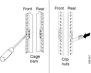
Step 2 ![]() Use a screwdriver to install the cage bars or the clip nuts on the inside of the mounting rail, as required for your rack, into the selected holes.
Use a screwdriver to install the cage bars or the clip nuts on the inside of the mounting rail, as required for your rack, into the selected holes.
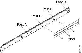
Step 3 ![]() The rail depth can be adjusted from 17 in (432 mm) to 31.25 in (794 mm). To adjust the depth, you can loosen the nuts on the posts and slide the bracket until the distance between the front and rear slide rail flanges matches the distance between the front and rear EIA rails of the rack cabinet. If you need further adjustment, remove the nuts, move the bracket to the appropriate set of posts (A, B, C, and D) to obtain the appropriate slide rail depth, then reinstall and tighten the nuts.
The rail depth can be adjusted from 17 in (432 mm) to 31.25 in (794 mm). To adjust the depth, you can loosen the nuts on the posts and slide the bracket until the distance between the front and rear slide rail flanges matches the distance between the front and rear EIA rails of the rack cabinet. If you need further adjustment, remove the nuts, move the bracket to the appropriate set of posts (A, B, C, and D) to obtain the appropriate slide rail depth, then reinstall and tighten the nuts.
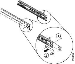
Step 4 ![]() To remove the support bracket, remove the screw (1) and remove the bracket (2) from the rear of the slide rail.
To remove the support bracket, remove the screw (1) and remove the bracket (2) from the rear of the slide rail.
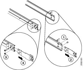
Step 5 ![]() To remove the mounting brackets, remove the screws (1) and (3). Slide out the brackets (2) and (4) from the rear of the slide rail.
To remove the mounting brackets, remove the screws (1) and (3). Slide out the brackets (2) and (4) from the rear of the slide rail.
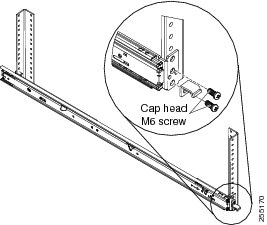
Step 6 ![]() Attach the front of the slide rail and EIA latch to the front of the rack cabinet by installing a screw in the bottom hole of the lower U; then, install another screw in the middle hole of the lower U to attach the front of the slide rail to the front of the rack cabinet.
Attach the front of the slide rail and EIA latch to the front of the rack cabinet by installing a screw in the bottom hole of the lower U; then, install another screw in the middle hole of the lower U to attach the front of the slide rail to the front of the rack cabinet.

Note ![]() When you fasten the slides to the rack, ensure the screws are engaged but the flange can move slightly. You will use a screwdriver to fully tighten them in Step 9.
When you fasten the slides to the rack, ensure the screws are engaged but the flange can move slightly. You will use a screwdriver to fully tighten them in Step 9.

Note ![]() Use 12-24 screws (not hex head M6 screws) on the front mounting bracket if you are installing this system into a rack with round or square holes (not threaded holes).
Use 12-24 screws (not hex head M6 screws) on the front mounting bracket if you are installing this system into a rack with round or square holes (not threaded holes).
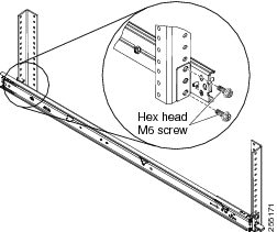
Step 7 ![]() Use two screws to attach the rear of the slide rail to the rear of the rack cabinet in the upper and the bottom holes of the lower U.
Use two screws to attach the rear of the slide rail to the rear of the rack cabinet in the upper and the bottom holes of the lower U.
Repeat Step 3 through Step 7 to install the other slide rail into the rack.
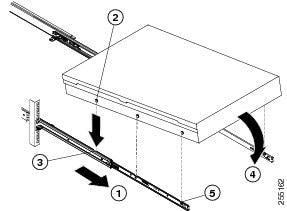
Step 8 ![]() Pull the slide rails forward (1) until they click, two times, into place. Carefully lift the NCS appliance and tilt it into position over the slide rails so that the rear nail heads (2) on the NCS appliance line up with the rear slots (3) on the slide rails. Slide the NCS appliance down until the rear nail heads slip into the two rear slots, and then slowly lower the front of the NCS appliance (4) until the other nail heads slip into the other slots on the slide rails. Make sure that the front latch (5) slides over the nail heads.
Pull the slide rails forward (1) until they click, two times, into place. Carefully lift the NCS appliance and tilt it into position over the slide rails so that the rear nail heads (2) on the NCS appliance line up with the rear slots (3) on the slide rails. Slide the NCS appliance down until the rear nail heads slip into the two rear slots, and then slowly lower the front of the NCS appliance (4) until the other nail heads slip into the other slots on the slide rails. Make sure that the front latch (5) slides over the nail heads.
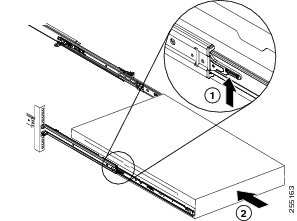
Step 9 ![]() Lift the locking levers (1) on the slide rails and push the NCS appliance (2) all the way into the rack until it clicks into place.
Lift the locking levers (1) on the slide rails and push the NCS appliance (2) all the way into the rack until it clicks into place.
Slide the system in and out twice to make sure the system slides correctly. Push the system inwards to the rack as close as possible but able to access the screws with a screwdriver. Then tighten the screws with a screwdriver.
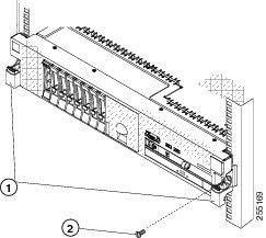
Step 10 ![]() Slide the NCS appliance into the rack until it snaps into place. To slide the NCS appliance out of the rack, press on the release latches (1).
Slide the NCS appliance into the rack until it snaps into place. To slide the NCS appliance out of the rack, press on the release latches (1).

Note ![]() When you move the rack cabinet, or if you install the rack cabinet in a vibration-prone area, insert the optional M6 screws (2) in the front of the NCS appliance.
When you move the rack cabinet, or if you install the rack cabinet in a vibration-prone area, insert the optional M6 screws (2) in the front of the NCS appliance.
To remove the NCS appliance from the rack, reverse these instructions. Store this information with your NCS appliance documentation for future use.
Front and Rear Panel
This section describes the controls and light-emitting diodes (LEDs) and how to turn the Cisco Prime Network Control System appliance on and off.
Front Panel
Figure 1-1 shows the controls, LEDs, and connectors the front panel of the Cisco Prime Network Control System appliance.
Figure 1-2 shows a detailed view of the operator information panel.
Figure 1-1 Cisco Prime Network Control System Appliance Front Panel

Front Panel Components
•![]() Rack release latches: Press the latches on each front side of the NCS appliance to remove it from the rack.
Rack release latches: Press the latches on each front side of the NCS appliance to remove it from the rack.
•![]() Hard disk drive status LEDs: This LED is used to indicate the status of the SAS hard disk drives. When this LED is lit, it indicates that the drive has failed. When this LED is flashing slowly (one flash per second), it indicates that the drive is being rebuilt. When the LED is flashing rapidly (three flashes per second), it indicates that the controller is identifying the drive.
Hard disk drive status LEDs: This LED is used to indicate the status of the SAS hard disk drives. When this LED is lit, it indicates that the drive has failed. When this LED is flashing slowly (one flash per second), it indicates that the drive is being rebuilt. When the LED is flashing rapidly (three flashes per second), it indicates that the controller is identifying the drive.
•![]() Hard disk drive activity LEDs: Each hot-swap hard disk drive has an activity LED, and when this LED is flashing, it indicates that the drive is in use.
Hard disk drive activity LEDs: Each hot-swap hard disk drive has an activity LED, and when this LED is flashing, it indicates that the drive is in use.
•![]() Optical drive eject button: Press this button to release a DVD or CD from the DVD drive.
Optical drive eject button: Press this button to release a DVD or CD from the DVD drive.
•![]() Optical drive activity LED: When this LED is lit, it indicates that the DVD drive is in use.
Optical drive activity LED: When this LED is lit, it indicates that the DVD drive is in use.
•![]() Operator information panel: This panel contains controls and LEDs that provide information about the status of the NCS appliance. For information about the controls and LEDs on the operator information panel, see Operator Information Panel.
Operator information panel: This panel contains controls and LEDs that provide information about the status of the NCS appliance. For information about the controls and LEDs on the operator information panel, see Operator Information Panel.
•![]() Operator information panel release latch: Slide the blue release latch to the left to pull out the light path diagnostics panel and view the light path diagnostics LEDs and buttons. See Light Path Diagnostics Panel for more information about the light path diagnostics.
Operator information panel release latch: Slide the blue release latch to the left to pull out the light path diagnostics panel and view the light path diagnostics LEDs and buttons. See Light Path Diagnostics Panel for more information about the light path diagnostics.
•![]() Video connector: Connect a monitor to this connector. The video connectors on the front and rear of the NCS appliance can be used simultaneously.
Video connector: Connect a monitor to this connector. The video connectors on the front and rear of the NCS appliance can be used simultaneously.

Note ![]() The maximum video resolution is 1600 x 1200 at 75 Hz.
The maximum video resolution is 1600 x 1200 at 75 Hz.
•![]() USB connectors: Connect a USB device, such as a USB mouse or keyboard, to any of these connectors.
USB connectors: Connect a USB device, such as a USB mouse or keyboard, to any of these connectors.
Operator Information Panel
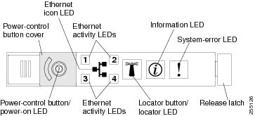
Figure 1-2 shows a detailed view of the controls and LEDs on the operator information panel.
Figure 1-2 Close Up of Cisco Prime Network Control System Appliance Operator Information Panel
Operator Information Panel Components
•![]() Power-control button and power-on LED: Press this button to turn the NCS appliance on and off manually or to wake it from a reduced-power state. The states of the power-on LED are as follows:
Power-control button and power-on LED: Press this button to turn the NCS appliance on and off manually or to wake it from a reduced-power state. The states of the power-on LED are as follows:
–![]() Off: Power is not present, or the power supply or the LED itself has failed.
Off: Power is not present, or the power supply or the LED itself has failed.
–![]() Flashing rapidly (4 times per second): The NCS appliance is turned off and is not ready to be turned on. The power-control button is disabled. This will last approximately 20 to 40 seconds.
Flashing rapidly (4 times per second): The NCS appliance is turned off and is not ready to be turned on. The power-control button is disabled. This will last approximately 20 to 40 seconds.
–![]() Flashing slowly (once per second): The NCS appliance is turned off and is ready to be turned on. You can press the power-control button to turn on the NCS appliance.
Flashing slowly (once per second): The NCS appliance is turned off and is ready to be turned on. You can press the power-control button to turn on the NCS appliance.
–![]() Lit: The NCS appliance is turned on.
Lit: The NCS appliance is turned on.
–![]() Fading on and off: The NCS appliance is in a reduced-power state. To wake the NCS appliance, press the power-control button.
Fading on and off: The NCS appliance is in a reduced-power state. To wake the NCS appliance, press the power-control button.
•![]() Ethernet activity LEDs: When any of these LEDs is lit, they indicate that the NCS appliance is transmitting to or receiving signals from the Ethernet LAN that is connected to the Ethernet port that corresponds to that LED.
Ethernet activity LEDs: When any of these LEDs is lit, they indicate that the NCS appliance is transmitting to or receiving signals from the Ethernet LAN that is connected to the Ethernet port that corresponds to that LED.
•![]() System-locator button/LED: Use this blue LED to visually locate the NCS appliance among other servers. This LED is also used as a presence detection button. When you press the System-locator button, the LED will blink and it will continue to blink until you press it again to turn it off.
System-locator button/LED: Use this blue LED to visually locate the NCS appliance among other servers. This LED is also used as a presence detection button. When you press the System-locator button, the LED will blink and it will continue to blink until you press it again to turn it off.
•![]() System-information LED: When this amber LED is lit, it indicates that a noncritical event has occurred.
System-information LED: When this amber LED is lit, it indicates that a noncritical event has occurred.
•![]() System-error LED: When this amber LED is lit, it indicates that a system error has occurred. A system-error LED is also on the rear of the NCS appliance. An LED on the light path diagnostics panel on the operator information panel is also lit to help isolate the error.
System-error LED: When this amber LED is lit, it indicates that a system error has occurred. A system-error LED is also on the rear of the NCS appliance. An LED on the light path diagnostics panel on the operator information panel is also lit to help isolate the error.
Light Path Diagnostics Panel
The light path diagnostics panel is on the top of the operator information panel, as shown in Figure 1-3. For additional information about the LEDs on the light path diagnostics panel, see Table 1-3.
To access the light path diagnostics panel, slide the blue release button on the operator information panel to the left. Pull forward on the unit until the hinge of the operator panel is free of the chassis. Then pull down on the unit, so that you can view the light path diagnostics panel information.

Note ![]() When you slide the light path diagnostics panel out of the NCS appliance to check the LEDs or checkpoint codes, do not run the NCS appliance continuously with the light path diagnostics panel outside of the NCS appliance. The panel should only be outside of the NCS appliance a short time. The light path diagnostics panel must remain in the NCS appliance when it is running to ensure proper cooling.
When you slide the light path diagnostics panel out of the NCS appliance to check the LEDs or checkpoint codes, do not run the NCS appliance continuously with the light path diagnostics panel outside of the NCS appliance. The panel should only be outside of the NCS appliance a short time. The light path diagnostics panel must remain in the NCS appliance when it is running to ensure proper cooling.
Figure 1-3 Light Path Diagnostics Panel
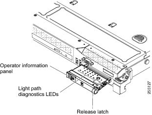
Figure 1-4 shows the LEDs and controls on the light path diagnostics panel.
Figure 1-4 Light Path Diagnostics Panel Components
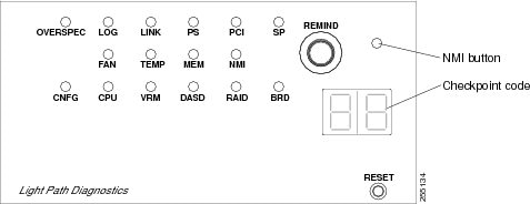
Light Path Diagnostics Panel Components
•![]() Remind button: This button places the system-error LED on the front panel into Remind mode. In Remind mode, the system-error LED flashes once every 2 seconds until the problem is corrected, the NCS appliance is restarted, or a new problem occurs.
Remind button: This button places the system-error LED on the front panel into Remind mode. In Remind mode, the system-error LED flashes once every 2 seconds until the problem is corrected, the NCS appliance is restarted, or a new problem occurs.
By placing the system-error LED indicator in Remind mode, you acknowledge that you are aware of the last failure but will not take immediate action to correct the problem.
•![]() NMI button: This button is used to force a nonmaskable interrupt to the microprocessor. This button is not currently used by the Cisco Prime Network Control System appliance. Press this button only when directed by the Cisco TAC personnel.
NMI button: This button is used to force a nonmaskable interrupt to the microprocessor. This button is not currently used by the Cisco Prime Network Control System appliance. Press this button only when directed by the Cisco TAC personnel.
•![]() Checkpoint code display: This display provides a checkpoint code that indicates the point at which the system stopped during the boot block and POST. A checkpoint code is either a byte or a word value that is produced by UEFI. The display does not provide error codes or suggest components to be replaced.
Checkpoint code display: This display provides a checkpoint code that indicates the point at which the system stopped during the boot block and POST. A checkpoint code is either a byte or a word value that is produced by UEFI. The display does not provide error codes or suggest components to be replaced.
•![]() Reset button: Press this button to reset the NCS appliance and run the power-on self-test (POST). You might have to use a pen or the end of a straightened paper clip to press the button. The Reset button is in the lower-right corner of the light path diagnostics panel.
Reset button: Press this button to reset the NCS appliance and run the power-on self-test (POST). You might have to use a pen or the end of a straightened paper clip to press the button. The Reset button is in the lower-right corner of the light path diagnostics panel.
|
|
||
|---|---|---|
|
|
|
|
None, but the system error LED is lit. |
An error occurred and cannot be isolated. The error is not represented by a path. |
Contact Cisco TAC for assistance. |
OVER SPEC |
The power supplies are using more power than their maximum rating. |
Contact Cisco TAC for assistance. |
LOG |
An error occurred. |
Contact Cisco TAC for assistance. |
LINK |
Reserved. |
- |
PS |
Power supply 1 or 2 has failed. |
1. 2. 3. 4. |
PCI |
An error has occurred on a PCI bus or on the system board. An additional LED is lit next to a failing PCI slot. |
Contact Cisco TAC for assistance. |
SP |
A service processor error has been detected. |
1. 2. |
FAN |
A fan has failed, is operating too slowly, or has been removed. The TEMP LED might also be lit. |
Contact Cisco TAC to replace your Cisco Prime Network Control System appliance and for further assistance. |
TEMP |
The system temperature has exceeded a threshold level. A failing fan can cause the TEMP LED to be lit. |
Contact Cisco TAC for assistance. |
MEM |
When only the MEM LED is lit, a memory error has occurred. When both the MEM and CNFG LEDs are lit, the memory configuration is invalid or the PCI Option ROM is out of resource. |
Contact Cisco TAC for assistance. |
NMI |
A nonmaskable interrupt has occurred, or the NMI button was pressed. |
Check the system-error log for information about the error. Contact Cisco TAC if further assistance is needed. |
CNFG |
A hardware configuration error has occurred. |
Contact Cisco TAC for assistance. |
CPU |
An invalid microprocessor configuration or a microprocessor has failed (both the CPU LED and the CNFG LED might be lit). |
Contact Cisco TAC for assistance. |
VRM |
Reserved. |
- |
DASD |
A hard disk drive has failed or is missing. |
1. 2. |
RAID |
Reserved. |
- |
BRD |
An error has occurred on the system board. |
Contact Cisco TAC for assistance. |
Rear Panel
Figure 1-5 shows details of the rear panel for the Cisco Prime Network Control System appliance.
Figure 1-6 shows the Cisco Prime Network Control System appliance back panel LEDs.
Figure 1-5 Cisco Prime Network Control System Appliance Rear Panel

Rear Panel Components
•![]() PCI slot 1: Cisco Prime Network Control System does not use this slot.
PCI slot 1: Cisco Prime Network Control System does not use this slot.
•![]() PCI slot 2: Cisco Prime Network Control System does not use this slot.
PCI slot 2: Cisco Prime Network Control System does not use this slot.
•![]() Power cord connectors: Connect the power cords to these connectors.
Power cord connectors: Connect the power cords to these connectors.

Note ![]() Power supply 1 is the default/primary power supply. If power supply 1 fails, you must replace it immediately.
Power supply 1 is the default/primary power supply. If power supply 1 fails, you must replace it immediately.
•![]() Video connector: Connect a monitor to this connector. The video connectors on the front and rear of the NCS appliance can be used simultaneously.
Video connector: Connect a monitor to this connector. The video connectors on the front and rear of the NCS appliance can be used simultaneously.

Note ![]() The maximum video resolution is 1600 x 1200 at 75 Hz.
The maximum video resolution is 1600 x 1200 at 75 Hz.
•![]() Serial connector: Connect the serial console cable to this connector.
Serial connector: Connect the serial console cable to this connector.
•![]() USB connectors: Connect a USB device, such as a USB mouse or keyboard to any of these connectors.
USB connectors: Connect a USB device, such as a USB mouse or keyboard to any of these connectors.
•![]() IMM 10/100 Mbps Ethernet port: For use in a future release.
IMM 10/100 Mbps Ethernet port: For use in a future release.
•![]() Ethernet connectors: Use Ethernet 1 to connect the NCS appliance to a network.
Ethernet connectors: Use Ethernet 1 to connect the NCS appliance to a network.
Figure 1-6 shows the LEDs on the rear of the NCS appliance.
Figure 1-6 Cisco Prime Network Control System Appliance Rear Panel LEDs

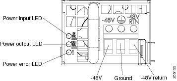
Figure 1-7 shows a detailed view of the LEDs on a DC power supply.
Figure 1-7 Close Up of Cisco Prime Network Control System Appliance DC Power Supply LEDs
•![]() Ethernet activity LEDs: When these LEDs are lit, they indicate that the NCS appliance is transmitting to or receiving signals from the Ethernet LAN that is connected to the Ethernet port.
Ethernet activity LEDs: When these LEDs are lit, they indicate that the NCS appliance is transmitting to or receiving signals from the Ethernet LAN that is connected to the Ethernet port.
•![]() Ethernet link LEDs: When these LEDs are lit, they indicate that there is an active link connection on the 10BASE-T, 100BASE-TX, or 1000BASE-TX interface for the Ethernet port.
Ethernet link LEDs: When these LEDs are lit, they indicate that there is an active link connection on the 10BASE-T, 100BASE-TX, or 1000BASE-TX interface for the Ethernet port.
•![]() AC power LED: Each hot-swap power supply has an AC power LED and a DC power LED. When the AC power LED is lit, it indicates that sufficient power is coming into the power supply through the power cord. During typical operation, both the AC and DC power LEDs are lit.
AC power LED: Each hot-swap power supply has an AC power LED and a DC power LED. When the AC power LED is lit, it indicates that sufficient power is coming into the power supply through the power cord. During typical operation, both the AC and DC power LEDs are lit.
•![]() IN OK power LED: Each hot-swap DC power supply has an IN OK power LED and an OUT OK power LED. When the IN OK power LED is lit, it indicates that sufficient power is coming into the power supply through the power cord. During typical operation, both the IN OK and OUT OK power LEDs are lit.
IN OK power LED: Each hot-swap DC power supply has an IN OK power LED and an OUT OK power LED. When the IN OK power LED is lit, it indicates that sufficient power is coming into the power supply through the power cord. During typical operation, both the IN OK and OUT OK power LEDs are lit.
•![]() DC power LED: Each hot-swap power supply has a DC power LED and an AC power LED. When the DC power LED is lit, it indicates that the power supply is supplying adequate DC power to the system. During typical operation, both the AC and DC power LEDs are lit.
DC power LED: Each hot-swap power supply has a DC power LED and an AC power LED. When the DC power LED is lit, it indicates that the power supply is supplying adequate DC power to the system. During typical operation, both the AC and DC power LEDs are lit.
•![]() OUT OK power LED: Each hot-swap DC power supply has an IN OK power LED and an OUT OK power LED. When the OUT OK power LED is lit, it indicates that the power supply is supplying adequate dc power to the system. During typical operation, both the IN OK and OUT OK power LEDs are lit.
OUT OK power LED: Each hot-swap DC power supply has an IN OK power LED and an OUT OK power LED. When the OUT OK power LED is lit, it indicates that the power supply is supplying adequate dc power to the system. During typical operation, both the IN OK and OUT OK power LEDs are lit.
•![]() System-error LED: When this LED is lit, it indicates that a system error has occurred. An LED on the light path diagnostics panel is also lit to help isolate the error.
System-error LED: When this LED is lit, it indicates that a system error has occurred. An LED on the light path diagnostics panel is also lit to help isolate the error.
•![]() Power-on LED: When this LED is lit and not flashing, it indicates that the NCS appliance is turned on. The states of the power-on LED are as follows:
Power-on LED: When this LED is lit and not flashing, it indicates that the NCS appliance is turned on. The states of the power-on LED are as follows:
–![]() Off: Power is not present, or the power supply or the LED itself has failed.
Off: Power is not present, or the power supply or the LED itself has failed.
–![]() Flashing rapidly (4 times per second): The NCS appliance is turned off and is not ready to be turned on. The power-control button is disabled. This will last approximately 20 to 40 seconds.
Flashing rapidly (4 times per second): The NCS appliance is turned off and is not ready to be turned on. The power-control button is disabled. This will last approximately 20 to 40 seconds.
–![]() Flashing slowly (once per second): The NCS appliance is turned off and is ready to be turned on. You can press the power-control button to turn on the NCS appliance.
Flashing slowly (once per second): The NCS appliance is turned off and is ready to be turned on. You can press the power-control button to turn on the NCS appliance.
–![]() Lit: The NCS appliance is turned on.
Lit: The NCS appliance is turned on.
–![]() Fading on and off: The NCS appliance is in a reduced-power state. To wake the NCS appliance, press the power-control button.
Fading on and off: The NCS appliance is in a reduced-power state. To wake the NCS appliance, press the power-control button.
•![]() System-locator LED: Use this LED to visually locate the NCS appliance among other servers. You can use the Integrated Management Module User's Guide to light this LED remotely.
System-locator LED: Use this LED to visually locate the NCS appliance among other servers. You can use the Integrated Management Module User's Guide to light this LED remotely.
Power-supply LEDs
Figure 1-8 shows the location of the power-supply LEDs on the rear of the Cisco Prime Network Control System appliance. See Table 1-4 for additional information about solving power-supply problems.
Figure 1-8 Location of Cisco Prime Network Control System Appliance Power Supply LEDs

Table 1-4 describes the problems that are indicated by various combinations of the power-supply LEDs on an AC power supply and suggested actions to correct the detected problems.
Cisco Prime Network Control System Appliance Power Features
Specific steps to power-on the Cisco Prime Network Control System appliance are provided in Powering On the Cisco Prime Network Control System Appliance.
When the NCS appliance is connected to an AC power source but is not turned on, the operating system does not run, and all core logic except for the service processor (the Integrated Management Module) is shut down; however, the NCS appliance can respond to requests to the service processor, such as a remote request to turn on the NCS appliance. The power-on LED flashes to indicate that the NCS appliance is connected to power but is not turned on.
Turning on the Cisco Prime Network Control System Appliance
Approximately 5 seconds after the NCS appliance is connected to power, one or more fans might start running to provide cooling while the system is connected to power, and the power-on button LED will blink quickly. Approximately 20 to 40 seconds after the NCS appliance is connected to power, the power-control button becomes active (the power-on LED will blink slowly), and one or more fans might start running to provide cooling while the NCS appliance is connected to power. You can turn on the NCS appliance by pressing the power-control button.
If a power failure occurs while the NCS appliance is turned on, the system will restart automatically when power is restored.
Turning off the Cisco Prime Network Control System Appliance
When you turn off the NCS appliance and leave it connected to power, it can respond to requests to the service processor, such as a remote request to turn on the NCS appliance. While the NCS appliance remains connected to power, one or more fans might continue to run. To remove all power from the NCS appliance, you must disconnect it from the power source.


The integrated management module (IMM) can turn off the NCS appliance as an automatic response to a critical system failure.
Replacing a Failed Hot-Swap Hard Disk Drive
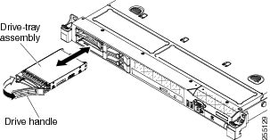
To replace a 2.5-inch hot-swap SAS hard disk drive, perform the following steps.
You can order replacement hard disk drives from Cisco. The replacement part PID is AIR-SRVR-300GB-HD=.
Step 1 ![]() Read the safety information in the "General Warnings, Regulatory and Safety" section.
Read the safety information in the "General Warnings, Regulatory and Safety" section.
Step 2 ![]() Touch the static-protective package that contains the drive to any unpainted metal surface on the NCS appliance; then, remove the drive from the package and place it on a static-protective surface.
Touch the static-protective package that contains the drive to any unpainted metal surface on the NCS appliance; then, remove the drive from the package and place it on a static-protective surface.
Step 3 ![]() Ensure that the drive you are replacing has failed before pulling it out of the drive slot. Press on the tray handle to unlock the drive. Pull on the tray handle to remove the drive.
Ensure that the drive you are replacing has failed before pulling it out of the drive slot. Press on the tray handle to unlock the drive. Pull on the tray handle to remove the drive.
Step 4 ![]() Install the hard disk drive in the drive bay as follows:
Install the hard disk drive in the drive bay as follows:
a. ![]() Make sure that the tray handle is in the open (unlocked) position.
Make sure that the tray handle is in the open (unlocked) position.
b. ![]() Align the drive assembly with the guide rails in the bay.
Align the drive assembly with the guide rails in the bay.
c. ![]() Gently push the drive assembly into the bay until the drive stops.
Gently push the drive assembly into the bay until the drive stops.
d. ![]() Rotate the tray handle to the closed (locked) position.
Rotate the tray handle to the closed (locked) position.
e. ![]() Check the hard disk drive status LED to verify that the hard disk drive is operating correctly. If the amber hard disk drive status LED for a drive is lit continuously, that drive is faulty and must be replaced. If the green hard disk drive activity LED is flashing, the drive is being accessed.
Check the hard disk drive status LED to verify that the hard disk drive is operating correctly. If the amber hard disk drive status LED for a drive is lit continuously, that drive is faulty and must be replaced. If the green hard disk drive activity LED is flashing, the drive is being accessed.
Replacing a Hot-Swap AC Power Supply
This section describes the type of AC power supply that the NCS appliance supports and other information that you must consider when you replace a failed power supply:
•![]() The Cisco Prime Network Control System appliance comes with two 675-watt hot-swap 12-volt output power supplies that connect to power supply bays 1 and 2. The input voltage is 110 VAC or 220 VAC auto-sensing.
The Cisco Prime Network Control System appliance comes with two 675-watt hot-swap 12-volt output power supplies that connect to power supply bays 1 and 2. The input voltage is 110 VAC or 220 VAC auto-sensing.
•![]() Power supply 1 is the default/primary power supply. If power supply 1 fails, you must replace the power supply immediately.
Power supply 1 is the default/primary power supply. If power supply 1 fails, you must replace the power supply immediately.
•![]() You can order replacement power supplies from Cisco. The replacement part PID is AIR-SRVR-PWR=.
You can order replacement power supplies from Cisco. The replacement part PID is AIR-SRVR-PWR=.
•![]() These power supplies are designed for parallel operation. In the event of a power-supply failure, the redundant power supply continues to power the system.
These power supplies are designed for parallel operation. In the event of a power-supply failure, the redundant power supply continues to power the system.


To install a hot-swap power supply, perform the following steps.
Step 1 ![]() Read the safety information in the "General Warnings, Regulatory and Safety" section.
Read the safety information in the "General Warnings, Regulatory and Safety" section.
Step 2 ![]() Touch the static-protective package that contains the hot-swap power supply to any unpainted metal surface on the NCS appliance; then, remove the power supply from the package and place it on a static-protective surface.
Touch the static-protective package that contains the hot-swap power supply to any unpainted metal surface on the NCS appliance; then, remove the power supply from the package and place it on a static-protective surface.
Step 3 ![]() Remove the failed power supply first. Grasp the handle on the rear of the power supply and slide the power supply out from the chassis.
Remove the failed power supply first. Grasp the handle on the rear of the power supply and slide the power supply out from the chassis.
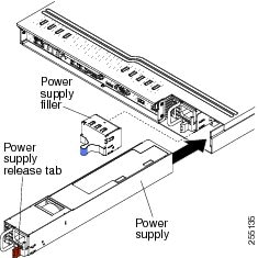
Step 4 ![]() Grasp the handle on the rear of the power supply and slide the power supply forward into the power-supply bay until it clicks. Make sure that the power supply connects firmly into the power-supply connector.
Grasp the handle on the rear of the power supply and slide the power supply forward into the power-supply bay until it clicks. Make sure that the power supply connects firmly into the power-supply connector.
Step 5 ![]() Route the power cord through the handle so that it does not accidentally become unplugged.
Route the power cord through the handle so that it does not accidentally become unplugged.
Step 6 ![]() Connect the power cord for the new power supply to the power-cord connector on the power supply.
Connect the power cord for the new power supply to the power-cord connector on the power supply.
Step 7 ![]() Connect the other end of the power cord to a properly grounded electrical outlet.
Connect the other end of the power cord to a properly grounded electrical outlet.
Step 8 ![]() Make sure that the AC power LED and the DC power LED on the AC power supply are lit, indicating that the power supply is operating correctly. The two green LEDs are to the right of the power-cord connector.
Make sure that the AC power LED and the DC power LED on the AC power supply are lit, indicating that the power supply is operating correctly. The two green LEDs are to the right of the power-cord connector.
Connecting the Cables
Figure 1-9 shows the locations of the input and output connectors on the front of the NCS appliance.
Figure 1-9 Front of Cisco Prime Network Control System Appliance

Figure 1-10 shows the locations of the input and output connectors on the rear of the NCS appliance.
Figure 1-10 Rear of Cisco Prime Network Control System Appliance

Connecting and Using the CLI Console
For initial system configuration, use the command-line interface (CLI) console. The CLI console connects to the NCS appliance back-panel DB9 console port. Figure 1-5 shows the console port on the back panel of the NCS appliance. Back panel components are described in Rear Panel Components.
Use the following terminal emulator settings for the CLI console session:
•![]() 9600 baud
9600 baud
•![]() 8 data bits
8 data bits
•![]() no flow control
no flow control
•![]() 1 stop bit
1 stop bit
•![]() no parity
no parity
Powering On the Cisco Prime Network Control System Appliance
When you apply AC power to an NCS appliance, the bootup script initializes the operating system and its stored configurations. You are prompted to enter a user ID and password and enter key configuration details.
To power on the NCS appliance, perform the following steps.
Step 1 ![]() Plug an AC power cord into the back of the two power supplies (Figure 1-5). If only one power supply is connected to a power source, the system will still function correctly but the monitoring components of the NCS appliance will detect the absence of the second power supply. The NCS appliance will raise an internal alarm, and a failure will be shown on the Administration > Appliance page. Connect the other end to a grounded 100 to 240 VAC 50/60 Hz electrical outlet.
Plug an AC power cord into the back of the two power supplies (Figure 1-5). If only one power supply is connected to a power source, the system will still function correctly but the monitoring components of the NCS appliance will detect the absence of the second power supply. The NCS appliance will raise an internal alarm, and a failure will be shown on the Administration > Appliance page. Connect the other end to a grounded 100 to 240 VAC 50/60 Hz electrical outlet.
The end of the power cord that plugs into the NCS appliance conforms with the IEC 320 standard.
Step 2 ![]() Use the front-panel Power On/Standby button, located in the operator information panel, to turn the NCS appliance on (Figure 1-2).
Use the front-panel Power On/Standby button, located in the operator information panel, to turn the NCS appliance on (Figure 1-2).
Step 3 ![]() At the login prompt, enter the NCS appliance operating user ID and password.
At the login prompt, enter the NCS appliance operating user ID and password.
The user ID and password are case sensitive.
You are now logged into the NCS appliance operating system.
Continue to the "Configuring the Cisco Prime Network Control System Appliance" section.
Configuring the Cisco Prime Network Control System Appliance
Minimal configuration is performed for the Cisco Prime Network Control System appliance as part of installation using the console. All configuration beyond the initial setup using the automatic installation is performed from the CLI after setup or from the NCS appliance GUI. For details on automatic installation, refer to the "Automatic Installation Script" section. The example installation shown in this section shows the two possible paths the setup may take: one for the HA primary machine and one for the HA secondary machine.
Automatic Installation Script
Step 1 ![]() When the appliance powers on for the first time, you will see the setup prompt. Enter setup at the prompt.
When the appliance powers on for the first time, you will see the setup prompt. Enter setup at the prompt.
**********************************************
Please type 'setup' to configure the appliance
**********************************************
localhost.localdomain login: setup
...
Step 2 ![]() You will be prompted by a series of system prompts to set up the NCS appliance. Enter the desired values at the system prompts.
You will be prompted by a series of system prompts to set up the NCS appliance. Enter the desired values at the system prompts.
Press 'Ctrl-C' to abort setup
The hostname should be a unique name that can identify the device on the network. The hostname should start with a letter, end with a letter or number, and contain only letters, numbers, and dashes.
Enter hostname []: myNCS
Enter IP address[]: 1.2.3.4
Enter IP default netmask[]: 255.255.255.0
Enter IP default gateway[]: 1.2.3.1
Enter DNS information. Enter a domain name for the network domain to which this device belongs. The domain name should start with a letter, and it should end with a valid domain name suffix such as .com. It must contain only letters, numbers, dashes, and dots.
Enter default DNS domain[]: mydomain.com
Enter primary nameserver[]: 1.2.3.2
Add/Edit another nameserver? Y/N : N
Enter NTP server information.

Note ![]() The NCS appliance and its associated controllers must be mapped to the same NTP server. An NTP server is required to automatically synchronize time between the controllers, the NCS appliance, and the mobility services engine.
The NCS appliance and its associated controllers must be mapped to the same NTP server. An NTP server is required to automatically synchronize time between the controllers, the NCS appliance, and the mobility services engine.

Note ![]() A list of available time zones in provided in Appendix A.
A list of available time zones in provided in Appendix A.
Enter primary NTP server[time.nist.gov]:
Add/Edit secondary NTP server? Y/N : N
Enter system timezone[UTC]: US/Pacific
Enter username[admin]:
Enter password:
Enter password again:
Bringing up network interface...
Pinging the gateway...
Pinging the primary nameserver...
Do not use 'Ctrl-C' from this point on...
Appliance is configured
Installing applications...
Installing NCS ...
************************************************
* Cisco Prime Network Control System Setup *
************************************************
Enter "^" to return to previous question.
HA Primary Machine
********************************************
* High Availability Role Selection *
********************************************
Will this server be used as a Secondary for HA? (yes/no)[no]:
********************************************
* Web Interface Root Password Selection *
********************************************
Enter root password:
Enter root password again:
********************************************
* FTP Password Selection *
********************************************
Enter ftp password:
Enter ftp password again:
************************************************
* Summary *
************************************************
Server will not be a Secondary
Root Password is set.
Ftp Password is set.
Apply these settings? (y/n)n
HA Secondary Machine
********************************************
* High Availability Role Selection *
********************************************
Will this server be used as a Secondary for HA? (yes/no)[no]:yes
********************************************
* Web Interface Root Password Selection *
********************************************
Enter root password:
Enter root password again:
********************************************
* FTP Password Selection *
********************************************
Enter ftp password:
Enter ftp password again:
************************************************
* Summary *
************************************************
Server will not be a Secondary
Root Password is set.
Ftp Password is set.
Apply these settings? (y/n)y
Settings Applied.
Application bundle (NCS) installed successfully
=== Initial Setup for Application: NCS ===
Running database cloning script...
Running database creation script...
Setting limits.conf file...
Turning on ipmi service...
Setting up NCS service...
Generating configuration...
Rebooting...
Logging in to the NCS Appliance
After the system reboots, perform the following steps to log in to the Cisco Prime Network Control System appliance.
Step 1 ![]() Log into the NCS server via Web browser as root user.
Log into the NCS server via Web browser as root user.
•![]() Login URL: https://hostname
Login URL: https://hostname
•![]() username: root
username: root
•![]() password: ********
password: ********
The root password is the Web password that was configured during setup. The root password can be changed after logging into the NCS via browser login.
Exporting Data from the Cisco Wireless Controller System
If you are migrating from a version of the Cisco Wireless Controller System (WCS) to the Cisco Prime Network Control System, perform the following steps to export data from the Cisco Wireless Controller System (WCS).

Note ![]() The current zip tool can handle zip files of up to only 4G in size. If the WCS database file is larger than 10G, it is highly possible that the zip file size will be larger than 4G. Please request a patch if you have this issue.
The current zip tool can handle zip files of up to only 4G in size. If the WCS database file is larger than 10G, it is highly possible that the zip file size will be larger than 4G. Please request a patch if you have this issue.
Step 1 ![]() Stop the existing WCS.
Stop the existing WCS.
Step 2 ![]() Execute the cd command to the bin directory.
Execute the cd command to the bin directory.
Step 3 ![]() Run the export using one of the following commands, depending on your operating system. Provide the path and export file name as prompted.
Run the export using one of the following commands, depending on your operating system. Provide the path and export file name as prompted.
•![]() In Linux: export.sh all /data/wcs.zip
In Linux: export.sh all /data/wcs.zip
•![]() In Windows: export.bat all c:/wcs.zip
In Windows: export.bat all c:/wcs.zip
Importing WCS data to the Cisco Prime Network Control System
NCS supports data migration from WCS release 7.0.164.3 only. For additional details and steps about migrating data from WCS to NSE, see the Cisco Prime NCS Prime Configuration Guide, Chapter 4: Performing Maintenance Operations, under the section "Performing NCS operations: Upgrading WCS to NCS" at the following URL:
http://www.cisco.com/en/US/products/ps11686/tsd_products_support_series_home.html
Configuring an NTP Server
You can configure NTP servers to set up the time and date of the NCS appliance.

Note ![]() You are automatically prompted to enable NTP and enter NTP server IP addresses as part of the automatic installation script. For more details on the automatic installation script, refer to the "Configuring the Cisco Prime Network Control System Appliance" section.
You are automatically prompted to enable NTP and enter NTP server IP addresses as part of the automatic installation script. For more details on the automatic installation script, refer to the "Configuring the Cisco Prime Network Control System Appliance" section.

Note ![]() For more information on the NTP configuration, consult the Linux configuration guide.
For more information on the NTP configuration, consult the Linux configuration guide.
During appliance setup, you were prompted to add an NTP server. Once the NCS appliance is up, the following command will allow you to change the NTP server configuration.
admin# configure
Enter configuration commands, one per line. End with CNTL/Z.
admin(config)# ntp ?
server Specify NTP server(s) to use
admin(config)# ntp server ?
<WORD> NTP server, IP or HOSTNAME (Max Size - 255)
admin(config)# ntp server 1.2.3.4 ?
<WORD> NTP server, IP or HOSTNAME (Max Size - 255)
<cr> Carriage return.
admin(config)# ntp server 1.2.3.4 1.2.3.5 ?
<WORD> NTP server, IP or HOSTNAME (Max Size - 255)
<cr> Carriage return.
admin(config)# ntp server 1.2.3.4 1.2.3.5 1.2.3.6 ?
<cr> Carriage return.
admin(config)# ntp server 1.2.3.4 1.2.3.5 1.2.3.6
Verifying the Cisco Prime Network Control System Appliance Software State
You can verify the NCS appliance software state at any time. In the NCS appliance CLI interface, enter the ncs status command.
If the NCS appliance is running, the command output looks like this example:
admin# ncs status
Health Monitor Server is running.
Reporting Server is Success
Ftp Server is Success
Database server is running
Tftp Server is Success
Matlab Server is Success
NMS Server is running.
admin#
If the NCS appliance is not running, the command output looks like the following example:
NCS Platform is down
Manually Stopping Cisco Prime Network Control System Appliance Software
The NCS appliance software automatically runs after initial configuration and after each reboot.
To manually stop and restart the software, perform the following steps :
Step 1 ![]() To stop the software, enter the following command:
To stop the software, enter the following command:
ncs stop
Step 2 ![]() To check status, enter the following command:
To check status, enter the following command:
ncs status
Step 3 ![]() To start the software, enter the following command:
To start the software, enter the following command:
ncs start
Emergency Recovery
Downloading and Burning the Recovery ISO Image to DVD
In an emergency situation, such as corrupted software, downgrade to an older release, or restoring a problematic appliance, perform the following steps to download and burn the desired recovery ISO image to DVD.
Step 1 ![]() The recovery ISO is available through Cisco TAC. Contact Cisco TAC to obtain the recovery ISO image file.
The recovery ISO is available through Cisco TAC. Contact Cisco TAC to obtain the recovery ISO image file.
Step 2 ![]() Download the recovery ISO image file.
Download the recovery ISO image file.
Step 3 ![]() Burn the recovery ISO image file to a DVD.
Burn the recovery ISO image file to a DVD.
Installing Recovery Image
Step 1 ![]() Reboot the NCS appliance with the recovery ISO DVD inserted. The Cisco Prime Network Control System Welcome screen appears.
Reboot the NCS appliance with the recovery ISO DVD inserted. The Cisco Prime Network Control System Welcome screen appears.
ISOLINUX 3.11 2005-09-02 Copyright (C) 1994-2005 H. Peter Anvin
Welcome to Cisco Prime Network Control System
To boot from hard disk, press <Enter>.
Available boot options:
[1] Network Control System Installation (Keyboard/Monitor)
[2] Network Control System Installation (Serial Console)
[3] Recover administrator password. (Keyboard/Monitor)
[4] Recover administrator password. (Serial Console)
<Enter> Boot existing OS from Hard Disk.
Enter boot option and press <return>.
boot:
Step 2 ![]() Select the desired install option, 1 or 2, depending on how you are connected to the appliance.
Select the desired install option, 1 or 2, depending on how you are connected to the appliance.
The installation will take approximately 30 minutes. After the ISO image is installed, the NCS appliance reboots. When the reboot completes, the following prompt will appear and the appliance will be wiped clean.
**********************************************
Please type 'setup' to configure the appliance
**********************************************
Recovering a Lost Admin Password
If you lose or forget the admin password for NCS appliance, follow these steps.
Step 1 ![]() Reboot the NCS appliance with the ISO DVD inserted. The Cisco Prime Network Control System Welcome screen appears.
Reboot the NCS appliance with the ISO DVD inserted. The Cisco Prime Network Control System Welcome screen appears.
ISOLINUX 3.11 2005-09-02 Copyright (C) 1994-2005 H. Peter Anvin
Welcome to Cisco Prime Network Control System
To boot from hard disk, press <Enter>.
Available boot options:
[1] Network Control System Installation (Keyboard/Monitor)
[2] Network Control System Installation (Serial Console)
[3] Recover administrator password. (Keyboard/Monitor)
[4] Recover administrator password. (Serial Console)
<Enter> Boot existing OS from Hard Disk.
Enter boot option and press <return>.
boot:
Step 2 ![]() Select the desired recovery option, 3 or 4, depending on how you are connected to the appliance.
Select the desired recovery option, 3 or 4, depending on how you are connected to the appliance.
 Feedback