Multiple PDN Attach or Detach Procedures

Feature Summary and Revision History

Summary Data

Table 1. Summary Data

Applicable Product(s) or Functional Area

cnSGW-C

Applicable Platform(s)

SMI

Feature Default Setting

Enabled - Always-on

Related Documentation

Not Applicable

Revision History

Table 2. Revision History

Revision Details

Release

First introduced.

2020.03.0

Feature Description

cnSGW-C handles the following functionalities:

  • UE-requested PDN connection

  • UE-requested PDN disconnection

  • PGW-initiated PDN disconnection

  • Admin-initiated disconnection.

How it Works

This section describes how this feature works.

Call Flows

This section describes the key call flows for this feature.

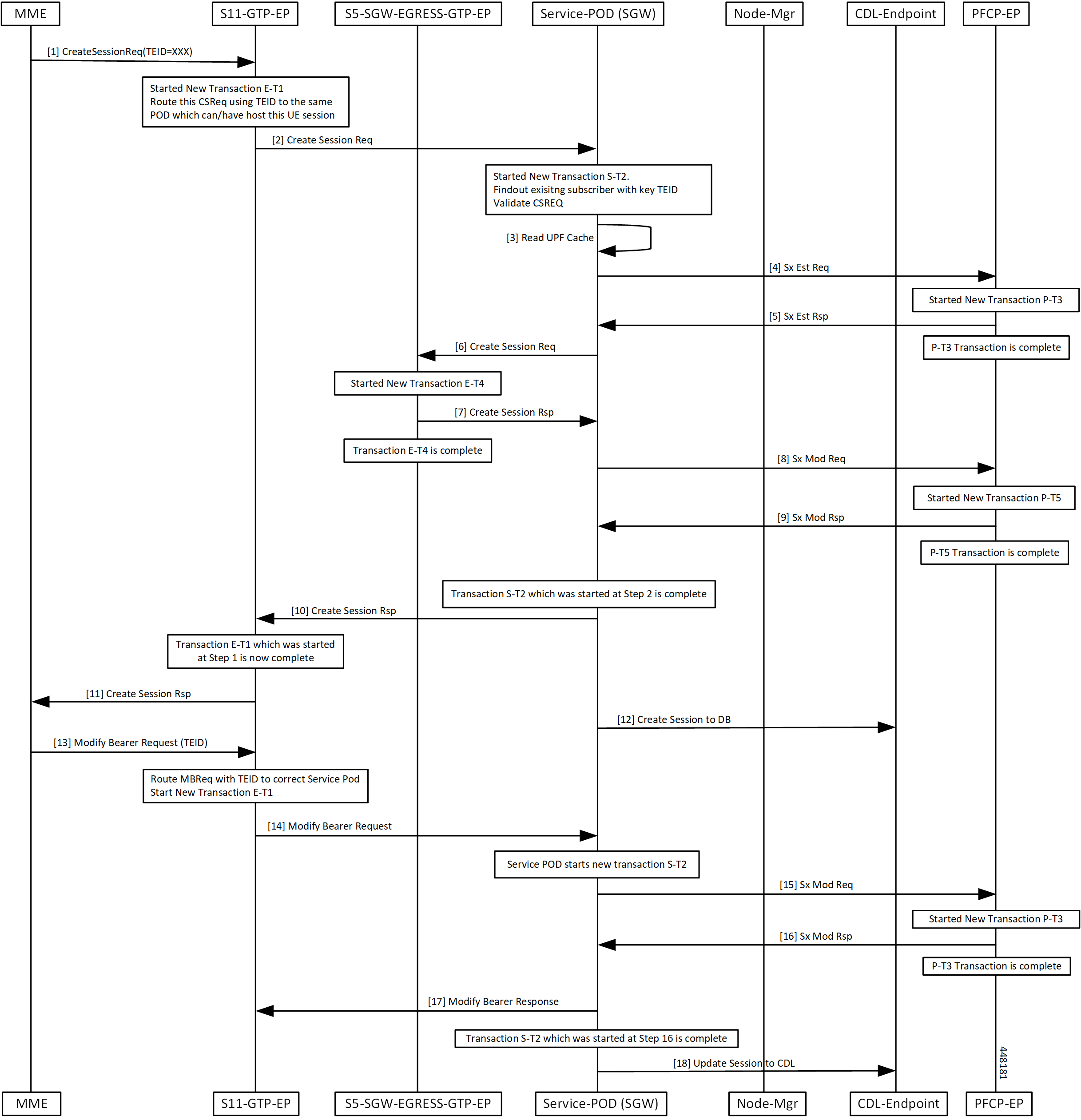
UE-requested PDN Connection Call Flow

This section describes the UE-requested PDN connection call flow.

Figure 1. UE-requested PDN Connection Call Flow
Table 3. UE-requested PDN Connection Call Flow Description

Step

Description

1

The MME sends the Create Session Request for a new PDN connection to the S11-GTP-EP with a nonzero TEID.

2

The E-T1 transaction is started.

The S11-GTP-EP decodes the received UDP message and converts the message into the gGRPC message. Based on the IMSI value, the message is forwarded to the respective SGW-service pod which handles the UE session.

The SGW-service pod receives the Create Session Request from the S11-GTP-EP.

3

The S-T2 transaction is started.

The SGW-service pod finds the subscriber context based on the local ingress TEID, and validates the Create Session Request content and updates the PDN and subscriber information.

The SGW-service pod reads the UPF cache to provide the selected UPF.

4

The SGW-service pod sends the Sx Establishment Request to the PFCP-EP.

5

The P-T3 transaction is started.

The PFCP-EP sends the Sx Establishment Response to the SGW-service pod.

6

The P-T3 transaction is completed.

The SGW-service pod sends the Create Session Request to the S5-SGW-EGRESS-GTP-EP with S11-U and S5-U TEID details.

7

The E-T4 transaction is started.

The Create Session Response is validated and the S5-U remote TEID is updated in the PDN.

The S5-SGW-EGRESS-GTP-EP sends the Create Session response to the SGW-service pod.

8

The E-T4 transaction is completed.

The SGW-service pod sends the Sx Modify Request to the PFCP-EP.

9

The P-T5 transaction is started.

The PFCP-EP sends the Sx Modify Response to the SGW-service pod on expiry of the timer T5.

10

The P-T5 and S-T2 transaction is completed.

The GTP-EP receives the Create Session Response from the SGW-service pod.

11

The E-T1 transaction is completed.

The MME receives the Create Session Response from the S11-GTP-EP.

12

The SGW-service pod updates the created session in CDL endpoint (database) with new PDN information.

13

The MME sends the Modify Bearer Request with TEID to the S11-GTP-EP.

14

The E-T1 transaction is started.

The S11-GTP-EP routes the Modify Bearer Request to the SGW-service pod.

The S11-GTP-EP sends the Modify Bearer Request to the SGW-service pod.

15

The S-T2 transaction is started.

The SGW-service pod sends the Sx Modify Request to the PFCP-EP pod on expiry of the timer S-T2.

16

The P-T3 transaction is started.

The PFCP-EP sends the Sx Modify Response to the SGW-service pod on expiry of the timer T3.

17

R-T3 transaction is completed.

The SGW-service pod sends the Modify Bearer Response to the MME.

18

S-T2 transaction is completed

The SGW-service pod sends the update session to the CDL endpoint.

UE-requested or the MME-requested PDN Disconnection Call Flow

This section describes the UE or the MME-requested PDN disconnection call flow.

Figure 2. UE-requested or the MME-requested PDN Disconnection Call Flow
Table 4. UE-requested or the MME-requested PDN Disconnection Call Flow Description

Step

Description

1

The MME sends the Delete Session Request to the S11-GTP-EP for other PDN disconnection.

2

The GTP-EP decodes the received UDP message and converts the message into the gRPC message.

Based on the TEID value, the gRPC message is forwarded to the SGW-service pod which can handle the UE session.

3

The SGW-service pod finds the subscriber context information as per the local ingress TEID.

The SGW-service pod validates the Delete Session Request content. The SGW-service pod sends the Sx Modify Request to the PFCP-EP with apply action as DROP to drop the uplink or downlink packets at the SGW-U.

4

The PFCP-EP sends the Sx Modify Response to the SGW-service pod.

5

The SGW-service pod forwards the Delete Session Request to the S5-SGW-EGRESS-GTP-EP.

6

The S5-SGW-EGRESS-GTP-EP forwards the Delete Session Request to the PGW through the UDP proxy.

7

The PGW sends the Delete Session Response to the S5-SGW-EGRESS-GTP-EP.

8

The S5-SGW-EGRESS-GTP-EP forwards the Delete Session Response to the SGW-service pod.

9

The SGW-service pod validates the Delete Session Response, and sends the Sx Delete Request to the PFCP-EP.

10

The SGW-service pod receives the Sx Delete Session Response from the PFCP-EP.

11

For the last PDN, the SGW-service pod sends the NodeMgrResourceManager Request for the ID release to the NodeManager.

12

The Node Manager releasees the ID and sends the acknowledgment to the SGW-service pod.

13

The SGW-service pod sends the Delete Session Response to the S11-GTP-EP.

14

The S11-GTP-EP forwards the Delete Session Response to the MME.

15

The SGW-service pod

  • Updates the session in database for the delete PDN information for other than the last PDN

  • Sends the delete session message to the database for the last PDN

PGW-requested Disconnection Call Flow

This section describes the PGW-requested disconnection call flow.

Figure 3. PGW-requested Disconnection Call Flow
Table 5. PGW-requested Disconnection Call Flow Description

Step

Description

1

The PGW sends the Delete Bearer Request to the S11-GTP-EP for other PDN disconnection.

2

The GTP-EP decodes the received UDP message and converts the message into the gRPC message.

Based on the TEID value, the gRPC message is forwarded to the SGW-service pod which can handle the UE session.

3

The SGW-service pod finds the subscriber context information as per the local ingress TEID.

The SGW-service pod validates the Delete Bearer Request content. The SGW-service pod sends the Sx Modify Request to the PFCP-EP with apply action as DROP to drop the uplink or downlink packets at the SGW-U.

4

The PFCP-EP sends the Sx Modify Response to the SGW-service pod.

5

The SGW-service pod forwards the Delete Bearer Request to the S5-SGW-EGRESS-GTP-EP.

6

The S5-SGW-EGRESS-GTP-EP forwards the Delete Bearer Request to the PGW through the UDP proxy.

7

The PGW sends the Delete Bearer Response to the S5-SGW-EGRESS-GTP-EP.

8

The S5-SGW-EGRESS-GTP-EP forwards the Delete Bearer Response to the SGW-service pod.

9

The SGW-service pod validates the Delete Bearer Response, and sends the Sx Delete Request to the PFCP-EP.

10

The SGW-service pod receives the Sx Delete Bearer Response from the PFCP-EP.

11

For the last PDN, the SGW-service pod sends the NodeMgrResourceManager Request for the ID release to the NodeManager.

12

The Node Manager releasees the ID and sends the acknowledgment to the SGW-service pod.

13

The SGW-service pod sends the Delete Bearer Response to the S11-GTP-EP.

14

The S11-GTP-EP forwards the Delete Bearer Response to the MME.

15

The SGW-service pod

  • Updates the Bearer in database for the delete PDN information for other than the last PDN

  • Sends the delete Bearer message to the database for the last PDN