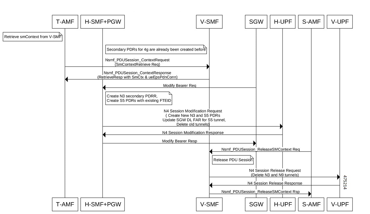
The show subscriber supi supi_id
nf-service smf psid psid_value full CLI command displays the detailed subscriber information for roaming-specific use case as hSMF.
[unknown] smf# show subscriber supi imsi-123456789012345 nf-service smf psid 5 full
subscriber-details
{
  "status": true,
  "genericInfo": {
    "supi": "imsi-310210789012346",
    "pei": "imei-123456786666660",
    "pduSessionId": 5,
    "pduSesstype": "Ipv4PduSession",
    "accessType": "3GPP_ACCESS",
    "dnn": "intershat",
    "plmnId": {
      "mcc": "310",
      "mnc": "560"
    },
    "sScMode": 1,
    "uetimeZone": "UTC+12:00",
    "allocatedIp": "209.165.200.229",
    "nrLocation": {
      "ncgi": {
        "mcc": "310",
        "mnc": "560",
        "nrCellId": "123456789"
      },
      "tai": {
        "mcc": "310",
        "mnc": "560",
        "tac": "1820"
      }
    },
    "alwaysOn": "None",
    "dcnr": "None",
    "wps": "Non-Wps Session",
    "ratType": "NR",
    "ueType": "NR Capable UE",
    "sessTimeStamp": "2021-06-18 18:49:28.266245111 +0000 UTC",
    "callDuration": "20.549700502s",
    "ipPool": "poolv4",
    "commonId": 2097158,
    "snssai": {
      "sd": "Abf123",
      "sst": 2
    },
    "authStatus": "Unauthenticated",
    "roamingStatus": "Roamer",
    "uePlmnId": {
      "mcc": "310",
      "mnc": "210"
    }
  },
  "accessSubData": {
    "amfID": "AFbe08",
    "amfPlmnId": {
      "mcc": "310",
      "mnc": "560"
    },
    "epsInterworkingIndication": "WITHOUT_N26"
  },
  "policySubData": {
    "TotalDynamicRules": 2,
    "TotalFlowCount": 2,
    "TotalNonGBRFlows": 1,
    "TotalGBRFlows": 1,
    "pccRuleList": [
      {
        "pccRuleId": "PccRule-1",
        "qfi": 2,
        "gbrDl": 2000000000,
        "gbrUl": 1000000000,
        "mbrDl": 4000000000,
        "mbrUl": 3000000000,
        "flowInformation": [
          {
            "flowLabel": "flow",
            "spi": "2",
            "flowDirection": 3,
            "flowDescription": "permit out ip from 209.165.200.225 to 209.165.200.254",
            "tosTrafficClass": "8"
          }
        ],
        "chargingInformation": {
          "chargingId": "ChargingData-1",
          "meteringMethod": "Duration and Volume",
          "Type": "Online",
          "ratingGroup": 10,
          "serviceId": "20"
        }
      },
      {
        "pccRuleId": "defaultrule",
        "qfi": 1,
        "mbrDl": 125000000,
        "mbrUl": 100000000,
        "flowInformation": [
          {
            "flowDirection": 3,
            "flowDescription": "permit out ip from any to any"
          }
        ]
      }
    ],
    "qosFlow": [
      {
        "qfi": 2,
        "GBRFlow": "True",
        "bindingParameters": {
          "x5Qi": 3,
          "arp": {
            "preemptCap": "NOT_PREEMPT",
            "preemptVuln": "PREEMPTABLE",
            "priorityLevel": 7
          }
        },
        "AggregatedULGFbr": 1000000000,
        "AggregatedDLGFbr": 2000000000,
        "AggregatedULMFbr": 3000000000,
        "AggregatedDLMFbr": 4000000000,
        "pccRuleList": "PccRule-1",
        "qosDescList": "QoS-1,"
      },
      {
        "qfi": 1,
        "GBRFlow": "False",
        "bindingParameters": {
          "x5Qi": 5,
          "arp": {
            "preemptCap": "NOT_PREEMPT",
            "preemptVuln": "NOT_PREEMPTABLE",
            "priorityLevel": 15
          },
          "priorityLevel": 1
        },
        "AggregatedULMFbr": 100000000,
        "AggregatedDLMFbr": 125000000,
        "pccRuleList": "defaultrule",
        "qosDescList": "default,"
      }
    ],
    "policyType": "Pcf",
    "pcfInteraction": "Pcf Interaction: ON",
    "ruleBase": "starent",
    "sessRuleList": [
      {
        "authDefaultQos": "&QosProfileKey{X5QI:5,Arp:{PreemptionCapability_NOT_PREEMPT PreemptionVulnerability_NOT_PREEMPTABLE 15 true},Priority:1,MaxDataBurstVol:0,Qnc:false,AveragingWindow:,}",
        "authSessAmbr": {
          "downlink": 125000000,
          "uplink": 100000000
        },
        "sessRuleId": "default"
      }
    ],
    "presenceReporting": "Disabled"
  },
  "chargingData": {
    "invcSeqNo": 1,
    "pduChId": 2097158,
    "ccId": "1",
    "chargingIdRtgGrpMapInfo": {
      "rgId": "10",
      "chargingId": [
        "ChargingData-1",
        "l10of",
        "l10on"
      ]
    },
    "chargParmMapInfo": [
      {
        "ratingGrp": 10,
        "chargingId": "ChargingData-1",
        "online": "true",
        "offline": "true",
        "serviceID": 20,
        "pccRuleIds": [
          "PccRule-1"
        ],
        "linkedChrgId": [
          "l10of",
          "l10on",
          "sesslevelurr"
        ],
        "meteringMthd": "MeteringMethod_DURATION_VOLUME",
        "reportingLevelOnline": "ReportingLevel_RAT_GR_LEVEL",
        "reportingLevelOffline": "ReportingLevel_RAT_GR_LEVEL",
        "configured": "false",
        "tightInterworkingMode": "false",
        "parent": "true",
        "reportingParm": "false",
        "limitParm": "false",
        "limitsChrgParamOnline": "l10on",
        "limitsChrgParamOffline": "l10of",
        "qosIds": [
          "QoS-1"
        ],
        "qfi": 2,
        "offlineConverted": "false"
      },
      {
        "ratingGrp": 10,
        "chargingId": "l10of",
        "online": "false",
        "offline": "true",
        "pccRuleIds": [
          "PccRule-1"
        ],
        "linkedChrgId": [
          "sesslevelurr"
        ],
        "meteringMthd": "MeteringMethod_DURATION_VOLUME",
        "reportingLevelOnline": "ReportingLevel_Dummy",
        "reportingLevelOffline": "ReportingLevel_RAT_GR_LEVEL",
        "configured": "false",
        "tightInterworkingMode": "false",
        "parent": "false",
        "reportingParm": "true",
        "limitParm": "true",
        "qosIds": [
          "QoS-1"
        ],
        "qfi": 2,
        "offlineConverted": "false"
      },
      {
        "ratingGrp": 10,
        "chargingId": "l10on",
        "online": "true",
        "offline": "false",
        "pccRuleIds": [
          "PccRule-1"
        ],
        "linkedChrgId": [
          "sesslevelurr"
        ],
        "meteringMthd": "MeteringMethod_DURATION_VOLUME",
        "reportingLevelOnline": "ReportingLevel_RAT_GR_LEVEL",
        "reportingLevelOffline": "ReportingLevel_Dummy",
        "configured": "false",
        "tightInterworkingMode": "false",
        "parent": "false",
        "reportingParm": "true",
        "limitParm": "true",
        "qosIds": [
          "QoS-1"
        ],
        "qfi": 2,
        "offlineConverted": "false"
      },
      {
        "chargingId": "sesslevelurr",
        "online": "false",
        "offline": "true",
        "pccRuleIds": [
          "PccRule-1"
        ],
        "meteringMthd": "MeteringMethod_DURATION_VOLUME",
        "reportingLevelOnline": "ReportingLevel_Dummy",
        "reportingLevelOffline": "ReportingLevel_Dummy",
        "configured": "false",
        "tightInterworkingMode": "false",
        "parent": "false",
        "reportingParm": "false",
        "limitParm": "true",
        "offlineConverted": "false"
      }
    ],
    "chTriggerInfo": {
      "sessionTriggerInfo": [
        {
          "triggerType": "VOLUME_LIMIT",
          "triggerCategory": "IMMEDIATE_REPORT",
          "triglevel": 2
        },
        {
          "triggerType": "TIME_LIMIT",
          "triggerCategory": "IMMEDIATE_REPORT",
          "triglevel": 2
        },
        {
          "triggerType": "AMBR_CHANGE",
          "triggerCategory": "IMMEDIATE_REPORT",
          "triglevel": 2
        },
        {
          "triggerType": "QOS_CHANGE",
          "triggerCategory": "DEFERRED_REPORT",
          "triglevel": 2
        }
      ],
      "rgTrgrList": [
        {
          "ratingGroup": 10,
          "rgTriggerInfo": [
            {
              "triggerType": "QUOTA_THRESHOLD",
              "triggerCategory": "IMMEDIATE_REPORT",
              "triglevel": 1
            },
            {
              "triggerType": "VOLUME_LIMIT",
              "triggerCategory": "IMMEDIATE_REPORT",
              "triglevel": 1
            },
            {
              "triggerType": "TIME_LIMIT",
              "triggerCategory": "IMMEDIATE_REPORT",
              "triglevel": 1
            },
            {
              "triggerType": "QUOTA_EXHAUSTED",
              "triggerCategory": "IMMEDIATE_REPORT",
              "triglevel": 1
            }
          ]
        }
      ]
    },
    "chThresholdInfo": {
      "sessthresholdInformation": {
        "volumeThreshold": 45000,
        "durationThreshold": 90
      },
      "rgthresholdInformation": [
        {
          "volumeThreshold": 7000,
          "durationThreshold": 800
        }
      ],
      "quotaInformation": [
        {
          "quotaHoldingTime": -1,
          "timeQuotaThreshold": 10,
          "volQuotaThreshold": 1000,
          "downlinkVolume": 20000,
          "time": 100,
          "totalVolume": 35000,
          "uplinkVolume": 15000,
          "ratingGrp": 10
        }
      ]
    },
    "startTime": "2021-06-18T18:49:28Z",
    "rulebase": "starent",
    "chargingDisabled": "false",
    "dropTraffic": "false",
    "gtppGrp": "group1",
    "profileName": "chgprf1",
    "accountingEnabled": "false",
    "n40ChargingEnabled": "true",
    "QbcProfileName": "qbc_general",
    "qbcChargingEnabled": "True",
    "roamingQbcInfo": {
      "qfiTh": {
        "volTh": 30000,
        "durTh": 80
      },
      "qfis": {
        "rgTriggerInfo": [
          {
            "triggerType": "QOS_CHANGE",
            "triggerCategory": "IMMEDIATE_REPORT",
            "triglevel": 2
          },
          {
            "triggerType": "TIME_LIMIT",
            "triggerCategory": "IMMEDIATE_REPORT",
            "triglevel": 2
          },
          {
            "triggerType": "VOLUME_LIMIT",
            "triggerCategory": "IMMEDIATE_REPORT",
            "triglevel": 2
          }
        ]
      },
      "partialRecordMethod": "PartialRecordMethod_DEFAULT"
    },
    "qbcChargParam": [
      {
        "chargingId": "qfi1",
        "qfi": 1,
        "meteringMthd": "MeteringMethod_DURATION_VOLUME",
        "reportingParam": "True",
        "limitParam": "True",
        "parent": "True"
      },
      {
        "chargingId": "qfi2",
        "qfi": 2,
        "meteringMthd": "MeteringMethod_DURATION_VOLUME",
        "reportingParam": "True",
        "limitParam": "True",
        "parent": "True"
      }
    ],
    "chfGroupId": "CHF-dnn=intershat;",
    "fbcChargingEnabled": "True"
  },
  "upfServData": {
    "numberOfTunnels": 1,
    "smfSeid": 9007228892966842,
    "qerInfo": [
      {
        "qosId": "Sess#Level",
        "qerId": 1,
        "refcnt": 1
      },
      {
        "qosId": "QoS-1@def#TC",
        "qerId": 2,
        "refcnt": 1
      },
      {
        "qosId": "default@def#TC",
        "qerId": 3,
        "refcnt": 1
      }
    ],
    "urrInfo": [
      {
        "chargingId": "ChargingData-1",
        "urrId": 16
      },
      {
        "chargingId": "l10of",
        "urrId": 33
      },
      {
        "chargingId": "l10on",
        "urrId": 55
      },
      {
        "chargingId": "sesslevelurr",
        "urrId": 76
      },
      {
        "chargingId": "qfi1",
        "urrId": 82
      },
      {
        "chargingId": "qfi2",
        "urrId": 98
      }
    ],
    "mapping": {
      "tunnelMapping": [
        {
          "TunnelID": 1,
          "tunnelName": "gnbTunnel",
          "RemoteTeid": {
            "teID": 1001,
            "ipAddr": "209.165.200.241"
          }
        }
      ]
    },
    "upfSeid": "17293822569102704642",
    "TotalNumberOfPdrs": "4 (Ul:2 Dl:2)",
    "TotalNumberOfFars": 4,
    "TotalNumberOfQers": 3,
    "TotalNumberOfUrrs": 6
  }
}


 Feedback