EPS Interworking

Feature Summary and Revision History

Summary Data

Table 1. Summary Data
Applicable Product(s) or Functional Area SMF
Applicable Platform(s) SMI
Feature Default Setting Enabled – Always-on
Related Changes in this Release Not Applicable
Related Documentation Not Applicable

Revision History

Table 2. Revision History
Revision Details Release

Added the following support:

  • Receiving QoS rules and QoS descriptions with the ePCO length of two octets option in PDU session establishment.

  • Indication of local IP address in TFT in S1 node during the PDU session establishment in 5G for a PDU session supporting 5G-4G internetworking.

  • Semantic and syntactic error handling for the QoS rules and Qos description or for mapped EPS Bearer Contexts errors from the UE.

  • Handles CB or UB response with ePCO containing 5GSM cause.

  • Mandatory MFBR validation while receiving GBR flow creation or QoS Modification from PCF.

  • HSS-initiated QoS modification for 4G UE.

2023.04.0

Added the following support:

  • For the change notification request received with ULI for 4G calls with legacy interfaces.

  • The alternate RAT tunnel creation for 4G.

  • Added the Show command for 4G call for the change in output of RAT Type.

2023.03.0

Added support for:

  • E-UTRAN initial attach procedure with Diameter interfaces.

  • Network-initiated Detach Procedures with Diameter Interfaces

  • PCRF-initiated CCAU or RAR

  • Modify Bearer Request with or without S-GW Change

  • UE-Initiated Detach Procedure

  • Support for Context Replacement

2023.02.0

FB Call Continuity Cause Code Expansion

2021.02.2

Added support for:

  • Configuring APN-AMBR action in Create Session Response

  • Container field—0005H (Selected Bearer Control Mode) for the PCO, ePCO, or aPCO IE in Create Session Response

  • GTP-C path failure detection and debugging improvements

  • GTP-C peer restart detection improvements

  • Handling the dedicated bearer procedure failures observed at the expiry of procedure SLA timer

2021.02.0

Introduced procedure to support dynamic configuration of the Access Profile configuration.

2020.03.0

New CLI command in the DNN profile configuration to reject calls from 4G-only UE devices.

2020.02.1

First introduced.

Pre-2020.02.0

Feature Description


Important


The PGW-C term used in this chapter denotes the EPS interworking functionality supported by SMF and must not be assumed as a standalone P-GW that is used in the LTE network.


EPS Interworking through 5G Core Network

The SMF implements the 3GPP recommendations for interworking of Evolved Packet System (EPS) and 5G Core Network (5GC).

The UEs capable of supporting both 4G and 5G NAS connect to the Evolved Terrestrial Radio Access Network (E-UTRAN) and the 5GC network. The SMF with the EPS interworking capability acts as a SMF and uses the S5 or S8 interface with S-GW to receive the 4G Session Creation Request. All the other interfaces involved in the 4G Session Creation (for example, Gx, Gy, Gz, and so on) are replaced by the corresponding 5GC Service Based Interfaces (for example, Npcf and Nchf).

After a PDU session is created on the SMF with E-UTRAN, Mobility Management Entity (MME) and Serving Gateway (S-GW), the UE can hand over E-UTRAN to 5G New Radio (NR) and conversely.

The SMF uses the N26 interface to interwork with EPS. This interface is an inter-CN interface between the MME and AMF and supports a subset of the functionalities over S10 interface to enable interworking.

The UE uses EPC NAS or 5GC NAS procedures depending on the core network by which it's served.

SMF Interworking with Diameter Interfaces

The Converged Core deployment allows signaling from a 4G subscriber. The SMF implements the 3GPP recommendations for interworking of Evolved Packet System (EPS) and Diameter Interfaces such as Gx for Policy, Gy for OCS, and Gz for offline charging. It also supports RADIUS authentication and accounting for subscribers. The signaling call flows and Pod level communications along with communication over various 3GPP interfaces is limited with only E-UTRAN access types.

Following are the SMF Diameter Interface call flow procedures for E-UTRAN access types:


Note


It should not be assumed that the Diameter interface features available on the SMF have full feature parity and functionality with StarOS or CUPS product.

Furthermore, it should not be assumed that any constructs (including, but not limited to, commands, statistics, attributes, MIB objects, alarms, logs, services) referenced in this document imply functional parity with StarOS legacy or CUPS products.

Please contact your Cisco Account or Support representative for any questions about parity between this product and any StarOS legacy or CUPS products.


Alternate RAT Tunnel Creation for 4G

SMF creates an alternate RAT tunnel during 4G sessions for 4G attach and dedicated bearer procedures. This tunnel is reused when a subscriber moves to another RAT during handover.


Note


  • Creation of an alternate RAT tunnel is a prerequisite for the inter-PLMN handover support.

  • SMF allocates an alternate RAT tunnel only if the EPS interworking is enabled.

  • SMF doesn't allocate the alternate RAT tunnel for 4G only UEs during 4G attach.


Architecture

The following figure shows the network architecture for the EPS-5G Core and 4G interworking.

Figure 1. 3GPP Non-Roaming Architecture for EPS-5GC Interworking

The following architecture diagram shows that SMF using Diameter interfaces for Policy and online charging and the Gz for the offline charging. It uses the N4 interface towards the UPF. In this architecture diagram, the grayed element are the 5G nodes that are not used for the 4G only UE.

Figure 2. SMF Interworking with Diameter and GTPP Interfaces

How it Works

Table 3. Feature History

Feature Name

Release Information

Description

Support for ePCO length and Local IP in TFT

2023.04

SMF allows ePCO length with two octets for QoS rules and QoS descriptions and indicate local IP address in TFT.

Default Setting: Enabled – Always-on

A UE that supports only EPS based Dual Connectivity with secondary RAT NR:

  • Always performs initial access through E-UTRA (LTE-Uu) but never through NR.

  • Performs EPS NAS procedures over E-UTRA (that is, Mobility Management, Session Management and so on) as defined in 3GPP TS 24.301.

A UE that supports camping on 5G Systems with 5GC NAS:

  • Performs initial access either through E-UTRAN that connects to 5GC or through NR towards 5GC.

  • Performs initial access through E-UTRAN towards EPS, if supported and needed.

  • Performs EPS NAS or 5GC NAS procedures over E-UTRAN or NR respectively (that is, Mobility Management, Session Management, and so on) depending on whether the UE requests 5GC access or EPS access, if the UE also supports EPS NAS.

For interworking with EPS, the UE that supports both 5GC and EPS NAS can operate in one of the following modes:

  • Single-registration mode: UE has only one active MM state (either RM state in 5GC or EMM state in EPS) and it is either in 5GC NAS mode or in EPS NAS mode (when connected to 5GC or EPS, respectively).

  • Dual-registration mode: UE handles independent registrations for 5GC and EPS using separate RRC connections. In this mode, the UE may be registered to 5GC only, EPS only, or to both 5GC and EPS.

Networks that support interworking with EPS, may support interworking procedures that use the N26 interface or interworking procedures that do not use the N26 interface.

  • Interworking procedures with N26 support provide IP address continuity on inter-system mobility to UEs that support 5GC NAS and EPS NAS and that operate in single registration mode. Interworking procedures using the N26 interface, enables the exchange of MM and SM states between the source and target network.

  • Networks that support interworking procedures without N26 support procedures to provide IP address continuity on inter-system mobility to UEs operating in both single-registration mode and dual-registration mode. For interworking without the N26 interface, IP address preservation is provided to the UEs on inter-system mobility by storing and fetching PGW-C+SMF and corresponding APN or DNN information via the HSS+UDM.

  • The UE operating in the S1 mode in a network supporting N26 interface also indicates the support for local IP address in TFT during the PDU session establishment procedure in 5G for supporting interworking with EPS.


Important


Interworking of SMF and EPS currently works only with the N26 interface.


Standards Compliance

The 5GC and EPS Interworking feature complies with the following standards:

  • 3GPP TS 23.401, Version 15.6.0

  • 3GPP TS 23.501, Version 15.4.0

  • 3GPP TS 23.502, Version 15.4.0

  • 3GPP TS 29.502, Version 15.2.1

  • 3GPP TS 29.512, Version 15.2.0

  • 3GPP TS 23.401, Version 5.3.2.1

Support for UE Initial Attach

Feature Description

The SMF supports the UE performing initial attach on E-UTRAN through MME and S-GW to create the default bearer.

Initial attach on E-UTRAN or EPS follows the procedure defined in 3GPP specification 23.401, Section 5.3.2.1. There are few deviations from the defined procedure to enable connectivity through the 5G core or Legacy GW. The deviations are as follows:

  • The Packet Data Network Gateway (PGW-C) in the procedure is replaced by SMF.

  • The IP-CAN Session establishment and modification is replaced by SM Policy Association Establishment procedure.

  • The online and offline charging functionality using Gy and Gz interfaces is replaced by integrated charging over Nchf interface with Charging Function (CHF).

  • The interface with the user-plane node is through N4 interface instead of Sxb interface.

SMF Interworking with Diameter Interfaces

The UE supports E-UTRAN Initial Attach procedures for Diameter interfaces as described in 5.3.2.1, 23.401 with following functions:

  • Default EPS bearer establishment.

  • Activate predefined PCEF rules with SMF as the Gx reference point is situated between the PCRF and the SMF. It is used for provisioning and removal of PCC rules. The Gx interface functions as a diameter connection. The Gx messages involve installing or removing dynamic rules and activating or deactivating predefined rules, APN-AMBR, and Default Bearer QoS.

How it Works

Call Flows

Initial Attach on E-UTRAN or EPS Procedure

The following figure shows the call flow derived from 3GPP reference for initial attach on E-UTRAN or EPS.

Figure 3. Call Flow for Initial Attach on E-UTRAN via 5G Core
Table 4. Call Flow Description for Initial Attach on E-UTRAN via 5G Core
Step Description
1 UE sends Attach Request to the MME through eNodeB.
2 The MME determines that the UE is capable and subscribed for handoff to NR. It selects an SMF node as the PGW-C for this PDU session.
3 The MME sends Create Session Request to the selected S-GW and includes the selected SMF address in it.
4 The S-GW initiates Create Session Request towards the SMF.
5 The SMF extracts the PDU Session ID sent by the UE in the Protocol Configuration Option (PCO) 001AH (PDU session ID) and saves it. It then performs a Unified Data Management (UDM) registration and sends PGW-C Fully Qualified Domain Name (FQDN) to the UDM. After registration, the SMF initiates subscription fetch from the UDM.
6

The SMF sends Npcf_SMPolicyControl_Create to the PCF to initiate SM policy Association Establishment.

The SMF includes the information elements received in Create Session Request message into the Npcf_SMPolicyControl_Create Service as follows:

  • The SUPI contains the IMSI.

  • The DNN contains the APN.

  • The PEI contains the IMEI-SV.

  • The Session AMBR contains the APN-AMBR.

  • The default QoS information contains the default EPS bearer QoS. The QCI values are mapped into 5QI values.

7 The SMF receives Policy Charging and Control (PCC) Rules and PDU Session Policy Information, 5G QoS information in PCC Rule and in PDU Session Policy Information which are mapped into EPS QoS information. The SMF creates Traffic Flow Template (TFT) from the Service Data Filters (SDFs) received in PCC rules and associates them with the corresponding default and dedicated bearers.
8 Based on the charging policies received from PCF, the SMF initiates Nchf_ConvergedCharging_Create operation towards the CHF. This procedure is similar to a 5G session and is based on the charging rules received from the PCF.
9 The SMF performs UPF+PGW-U selection and N4 Session Establishment. Since this is a 4G session connecting the SMF, a separate CN tunnel is created for each bearer and QoS Flow ID (QFI) is not sent in the QoS Enforcement Rule (QER) and Packet Detection Rule (PDR).
10

The SMF sends Create Session Response to S-GW and includes the bearer information and Tunnel Endpoint Identifier (TEID) for the default bearer. The SMF also includes the 5G QoS parameters in PCO and ePCO options 001CH/0023H (QoS rules), 001DH (Session-AMBR), 001EH (PDU session address lifetime) and 001FH/0024H (QoS flow descriptions) to the UE.

The SMF populates the container identifier 0005H (Selected Bearer Control Mode) in PCO, ePCO, and aPCO IE in Create Session Response. The container identifier contents field with value 2 indicates that the MS/NW mode is selected.

11 The S-GW sends Create Session Response to the MME.
12 The MME sends Initial Context Setup Request to the eNodeB with N1 Attach Accept message.
13 The eNodeB and UE perform Radio Resource Control (RRC) configuration.
14 The UE sends Direct transfer message to the eNodeB.
15 The eNodeB sends Attach Complete message in Initial Context Setup Response to the MME along with the TEID of eNodeB.
16 The MME sends a Modify Bearer Request to the S-GW with eNodeB TEID.
17 The SMF sends the Modify Bearer Response to the S-GW.
18 The S-GW sends Modify Bearer Response to the MME.
Initial Attach on E-UTRAN with Diameter Interfaces

A UE needs to register with the network to receive services that require registration.

The following figure shows the call flow derived from the 3GPP reference for initial attach on E-UTRAN with Diameter interfaces Gx and Gy.

Figure 4. Call Flow for E-UTRAN Initial Attach
Table 5. Call Flow Description for E-UTRAN Initial Attach
Step Description
1

MME sends Create Session Request to S-GW.

2

S-GW sends Create Session Request to SMF.

Note

 
As part of this call flow, Secondary Authentication using RADIUS gets enabled in a DNN profile, and the AAA server is selected based on the RADIUS profile configuration.

3

SMF sends RADIUS Access-Request to AAA server for authentication.

4

AAA Server sends Access-Accept to SMF.

Note


SMF assigns IP Address, commonId allocation, and UPF selection. SMF selects PCRF server based on Diameter endpoint profile configuration.

5

SMF sends Gx Credit Control Request Initial to PCRF server requesting for policy.

6

PCRF Server sends Gx Credit Control Answer Initial to SMF.

Note

 
SMF selects the Online Charging System (OCS) server based on the Diameter endpoint profile configuration.

7

SMF sends Gy Credit Control Request Initial to the OCS server requesting for quota.

Note

 
If the diameter send- ccri traffic-start is not configured, CCR-I is sent to OCS without any quota request after the Gx response for the default bearer. A successful response from OCS results in continuation of the Initial Attach procedure.

8

OCS server sends Gy Credit Control Answer Initial to SMF.

9

SMF sends Radius Accounting request start to AAA Server.

10

AAA Server sends Radius Accounting Response to SMF.

11

SMF sends N4 PFCP Session Establishment Request to UPF to create PDRs/FARs/QERs/URRs.

12

UPF sends N4 PFCP Session Establishment response to SMF.

13

SMF sends Create Session Response to S-GW.

14

S-GW sends Create Session Response to MME

15

MME sends Router solicitation to S-GW for IPv6 call.

16

S-GW sends Router Solicitation to UPF for IPv6 call.

17

UPF sends Router Advertisement to S-GW for IPv6 call.

18

S-GW sends Router Advertisement to MME for IPv6 call.

Context Replacement Call Flow

The SMF supports the context replacement procedure, when it receives a Create Session Request (CSReq) with the existing IMSI and EBI combination for which there’s an existing subscriber.

The SMF can receive a CSReq for an already existing session. When the new CSReq is received, the existing session gets replaced with the new session, based on the new request. The context replacement procedure also referred as the create-over-create procedure.

As a first step in this process, the disconnect procedure for an existing session gets initiated. Later, it establishes a session based on the new request.

The following image describes the context replacement procedure call flow.

Figure 5. Call Flow for the Context Replacement Procedure
Table 6. Call Flow Description for the Context Replacement Procedure

Step

Description

1

The MME sends a Create Session Request to the S-GW.

2

The S-GW sends a Create Session Request to the SMF.

Note


A stale session was already present for this IMSI and EBI combination. The disconnect procedure gets started for the existing session.

3

The SMF sends a PFCP Session Deletion Request to the UPF.

4

The UPF sends a PFCP Session Deletion Response to the UPF.

5

The SMF sends an Async RADIUS Accounting-Request Stop to the AAA server.

6

The SMF sends an Async Gx CCR-T to the PCRF.

7

The SMF sends an Async Gy CCR-T to the OCS.

8

The AAA server sends a RADIUS Accounting-Response to the SMF.

9

The PCRF sends a Gx CCA-T to the SMF.

10

The OCS sends a Gy CCA-T to the SMF.

Note


After this action, the connect procedure continues for the new request.


Note


The order in which the response messages outlined in Steps 8–10 is subject to change depending on the availability.


Configuring UE Initial Attach

This section describes how to configure the UE Initial Attach .

Configuring the UE Initial Attach involves the following steps:

  1. Define FQDN in SMF Profile Configuration

  2. Configure S5 Binding Address in SMF Service Configuration

  3. Enable Kubernetes Configuration for SMF GTP Endpoint PODs

Define FQDN in SMF Profile Configuration

Use the following configuration to specify the FQDN of SMF. The configured FQDN is sent to the UDM during registration.


config 
   profile smf smf_profile_name 
   instances instance_id  fqdn fqdn_name 
      end 

NOTES:

  • instances instance_id fqdn fqdn_name : Configures the PGW-C FQDN corresponding to the local or remote instances. fqdn_name must be an alphanumeric string.

Configure S5 Binding Address

To define the S5 binding address at which the SMF listens for GTP messages from S-GW (S5 interface), use the following sample configuration:

config 
   instance instance-id instance_id 
      endpoint gtp 
         replicas replica_count 
         nodes node_id 
         enable-cpu-optimization true 
         interface s5 
         vip-ip vip_ip_address 
         exit 
      interface s5e 
         echo 
         vip-ip vip_ip_address 
         exit 
      interface s2b 
         vip-ip vip_ip_address 
         end 

NOTES:

  • interface s5 : Configure the S5 interface through which the messsges are sent from S-GW to SMF.

  • vip-ip vip_ip_address : Enter the IP address at which SMF listens for GTP messages from S-GW through S5 interface. Enter the address in either standard IPv4 dotted decimal format or in standard IPv6 colon notation format.

Configuring GTP Endpoint Parameters

Use the following sample configuration to define the GTP endpoint parameters.

config 
   instance instance-id gr_instance_id 
      endpoint gtp 
         replicas replica_count 
         vip-ip ipv4_address 
         vip-ipv6 ipv6_address 
         end 

NOTES:

  • endpoint gtp : Enter the GTP endpoint configuration.

  • replicas replica_count : Enter the number of replicas to be created per node. The default value is 1.

  • vip-ip : Specify the IPv4 address for the GTP endpoint.

  • vip-ipv6 : Specify the IPv6 address for the GTP endpoint.

Configuring APN-AMBR in CSR

The SMF sends APN-AMBR in Create Session Response if it is not received in Create Session Request or if the value has changed as part of PCF negotiation. The configuration under access profile overrides this behaviour.

Use the following sample configuration to configure the APN-AMBR action in Create Session Response.

config 
   profile access access_profile_name 
      gtpc message-handling create-session-response action apn-ambr 
      exit 

NOTES:

  • action apn-ambr : Specifies the APN-AMBR action for the GTPC message.

Configuring PCRF, PCF, and OCS Interfaces

You can add Policy profiles under a dnnprofile to have configurations for 5G subscribers (N7 or N40 interface) and 4G subscribers (Gx, or Gy/Gz).


Important


If the Gx (PCRF), Gy (OCS), Gz (CGF), or N40 (CHF) is not enabled, SMF will not interact with these interfaces.


Configure PCRF Interfaces

Use the following commands to configure a PCRF interface.

config 
   profile dnn dnnprofile-ims   
   network-element-profiles pcrf pcrf pcrf1 
      exit 

NOTES

  • network-element-profiles pcrf pcrf1: Specifices the PCRF message handling profile configuration.

Configure PCF Interfaces

Use the following commands to configure a PCF interface.

config 
   profile dnn dnnprofile-ims   
   network-element-profiles pcf pcf nfprf-pcf1  
      exit 

NOTES

  • network-element-profiles pcf pcf nfprf-pcf1 : Specifies the PCF message handling profile configuration.

Configure OCS Interfaces

Use the following commands to configure an OCS interface.

config 
   profile dnn dnnprofile-ims   
   network-element-profiles ocs  ocs1 
      exit 

NOTES

  • network-element-profiles ocsocs1 : Specifies the OCS message handling profile configuration.

Verifying the UE Initial Attach Configuration

This section describes how to verify the UE Initial Attach configuration.

The following configuration is a sample output of the show running-config command:

show running-config 
. 
. 
. 
profile smf smf1 
 node-id          ABC123 
 bind-address ipv4 209.165.200.230 
 bind-port        8008 
instances 1  allowed-nssai  [ slice1 ] 
 plmn-id mcc 123 
 plmn-id mnc 456 
 fqdn ciscosmf1 
 service name nsmf-pdu 
  type               pdu-session 
  . 
  . 
  . 
  n4 bind-address ipv4 209.165.200.240 
  s5 bind-address ipv4 209.165.200.240 
  http-endpoint base-url http://smf-service 
. 
. 
. 
k8 smf local redis-endpoint redis-primary:6379 
k8 smf local service no-of-replicas 1 
k8 smf local nodemgr no-of-replicas 1 

. 
. 
. 

OAM Support

This section describes operations, administration, and maintenance information for this feature.

Show Command Support

Use the show subscriber supi imsi imsi_value nf-service smf full command to view the configuration related to the subscriber details for a 4G call.

The following is an example output.

smf# show subscriber supi imsi-123456789012345 nf-service smf full
subscriber-details
{
  "subResponses": [
    {
      "status": true,
      "genericInfo": {
        "supi": "imsi-123456789012345",
        "pei": "imeisv-1122334455667788",
        "pduSessionId": 69,
        "pduSesstype": "Ipv4V6PduSession",
        "accessType": "3GPP_ACCESS",
        "dnn": "intershat",
        "plmnId": {
          "mcc": "123",
          "mnc": "765"
        },
        "sScMode": 1,
        "allocatedIp": "12.0.0.4",
        "allocatedIpv6": "2001:db0:0:2003::",
        "allocatedIntfid": "tG1H//5HR0c=",
        "eUtranLocation": {
          "ecgi": {
            "mcc": "214",
            "mnc": "365",
            "eutraCellId": "1234567"
          },
          "tai": {
            "mcc": "214",
            "mnc": "365",
            "tac": "6789"
          },
          "ueLocationTimestamp": "2022-08-08T13:16:09Z"
        },
        "alwaysOn": "None",
        "dcnr": "None",
        "wps": "Non-Wps Session",
        "ratType": "EUTRA",
        "ueType": "4G Capable UE",
        "sessTimeStamp": "2022-08-08 13:16:09.107469768 +0000 UTC",
        "callDuration": "3.531530696s",
        "ipPool": "poolv4",
        "ipv6Pool": "poolv6",
        "commonId": 2097156,
        "linkedEbi": 5,
        "snssai": {
          "sd": "Abf123",
          "sst": 2
        },
        "authStatus": "Unauthenticated",
        "roamingStatus": "Roamer",
        "uePlmnId": {
          "mcc": "123",
          "mnc": "456"
        },
      }
    }
  ]
}

Note


In the preceding output example, for a 4G call, the RAT Type appears as "EUTRA".


Detach Procedure for EPS on SMF

Feature Description

EPS Interworking through 5G Core Network

The SMF supports the default bearer deletion procedures for a UE attached through E-UTRAN, MME, and S-GW.

SMF Interworking with Diameter Interfaces

When the UE is attached to the E-UTRAN, SMF supports the following Network-initiated detach procedures with Diameter interfaces:

  • SMF-initiated detach procedure

  • UPF-initiated detach procedure

  • PCRF-initiated detach procedure

  • UE-initiated detach procedure

  • RADIUS-initiated detach procedure

How it Works

Call Flows

This section describes the call flows associated with this feature.

UE-initiated EPS Call Release Procedure

The following figure shows the call flow for UE-initiated release of EPS call.

Figure 6. UE-initiated EPS Call Release Flow

The detach procedures for the EPS are defined in 3GPP 23.401, Section 5.3.8. When the UE is attached to E-UTRAN, the detach procedure remains the same as mentioned in the specified 3GPP section except for the following changes:

  • Any interaction towards PCRF (CCR-T), that is PCEF-initiated IP-CAN session between PGW-C and PCRF, is replaced by Npcf_SMPolicyControl_Update Request from the SMF to the PCF. The parameters sent in this message follow a mapping from Delete Session Request contents in a way similar to the Create Session Request message for initial attach.

  • All Gy and Gz interface messages are replaced by Nchf_ConvergedCharging_Release service operations.

  • The user plane resources are removed using the N4 Session Release procedure towards the UPF.

UE-initiated Call Release Detail Procedure

The following figure shows the detailed procedure of UE-initiated release of EPS call.

Figure 7. Detailed Call Flow of UE-initiated EPS Call Release
PCF-initiated Call Release Detail Procedure

The following figure shows the detailed procedure of PCF-initiated release of EPS call.

Figure 8. Detailed Call Flow of PCF-initiated EPS Call Release
Network-initiated Detach Procedures with Diameter Interfaces

This section describes Network-initiated Detach call flows and procedures.

SMF Initiated Detach Procedure

SMF receives a request for session release through one of the following methods:

  • Clear Subscriber

  • GTP Path Failure

  • Peer Restart

  • Absolute Session Timeout

  • Cp-idle Timeout

The following call flow illustrates the procedure of an E-UTRAN network (SMF) initiated detach.

Figure 9. Call Flow for SMF-initiated Detach
Table 7. Call Flow Description for SMF Initiated Detach
Step Description
1

SMF sends N4 PFCP Session Modification Request to UPF with FARs having apply action set to Drop.

2

UPF sends N4 PFCP Session Modification Response to SMF.

3

SMF sends Delete Bearer Request to S-GW.

4

S-GW sends Delete Bearer Request to MME.

5

MME sends Delete Bearer Response to S-GW.

6

S-GW sends Delete Bearer Response to SMF.

7

SMF sends N4 PFCP Session Deletion Request to UPF to release N4 session.

8

UPF sends N4 PFCP Session Deletion Response to SMF.

9

SMF sends Radius Accounting Request Stop to AAA server to release the accounting session.

10

AAA server sends Radius Accounting Response to SMF.

11

SMF sends Gx Credit Control Request Terminate to OCS to release the Gy session.

12

OCS sends Gx Credit Control Answer Terminate to SMF.

13

SMF sends Gx Credit Control Request Terminate to PCRF to release the Gx session.

14

PCRF sends Gx Credit Control Answer Terminate to SMF.

UPF-initiated Detach Procedure

The following call flow illustrates an E-UTRAN network (UPF) initiated detach.

Figure 10. Call Flow for UPF-initiated Detach
Table 8. Call Flow Description for UPF-initiated Detach
Step Description
1

UPF sends N4 Session Report Request (ERIR[default bearer]/UPIR) to SMF.

Note


Session Report Request of type ERIR is received when GTP-U Error Indication is received at UPF. Session Report Request of type UPIR is received when the UPF inactivity timer is expired on UPF. Both of these (In case, ERIR is received on default bearer) lead to session termination.

2

SMF sends N4 Session Report Response to UPF.

3

SMF sends N4 PFCP Session Modification Request to UPF with FARs having apply action set to drop

4

UPF sends N4 PFCP Session Modification Response to SMF.

5

SMF sends Delete Bearer Request to S-GW.

6

S-GW sends Delete Bearer Request to MME.

7

MME sends Delete Bearer Response to S-GW.

8

S-GW sends Delete Bearer Response to SMF.

9

SMF sends N4 PFCP Session Deletion Request to UPF to release N4 session.

10

UPF sends N4 PFCP Session Deletion Response to SMF.

11

SMF sends Radius Accounting Request Stop to AAA server to release the accounting session.

12

AAA server sends Radius Accounting Response to SMF.

13

SMF sends Gy Credit Control Request Terminate to OCS to release the Gy session.

14

OCS sends Gy Credit Control Answer Terminate to SMF.

15

SMF sends Gx Credit Control Request Terminate to PCRF to release the Gx session.

16

PCRF sends Gx Credit Control Answer Terminate to SMF.

PCRF-initiated Detach Procedure

The following call flow illustrates the procedure in which the E-UTRAN network (PCRF) initiated detach.

Figure 11. Call Flow for PCRF-initiated Detach
Table 9. Call Flow Description for PCRF-initiated Detach
Step Description
1

PCRF sends Gx Credit Control Answer or RAR with session release cause to SMF.

2

SMF sends N4 PFCP Session Modification Request to UPF with FARs having apply action set to Drop

3

UPF sends N4 PFCP Session Modification Response to SMF.

4

SMF sends Delete Bearer Request to S-GW.

5

S-GW sends Delete Bearer Request to MME.

6

MME sends Delete Bearer Response to S-GW.

7

S-GW sends Delete Bearer Response to SMF.

8

SMF sends N4 PFCP Session Deletion Request to UPF to release N4 session.

9

UPF sends N4 PFCP Session Deletion Response to SMF.

10

SMF sends Radius Accounting Request Stop to AAA server to release radius session.

11

AAA server sends RADIUS Accounting Response to SMF.

12

SMF sends Gx Credit Control Request Terminate to OCS to release Gy session.

13

OCS sends Gx Credit Control Answer Terminate to SMF.

14

SMF sends Gx Credit Control Request Terminate to PCRF to release Gx session.

15

PCRF sends Gx Credit Control Answer Terminate to SMF.

UE Initiated Detach Procedure

The following figure shows the call flow for an UE-initiated release with Diameter interfaces.

Figure 12. Call Flow for UE Initiated Release with Diameter Interfaces

The following table describes the detailed procedure of an E-UTRAN UE-initiated detach.

Table 10. Call Flow Description for UE Initiated Release with Diameter Interfaces
Step Description
1

MME sends Delete Session Request to S-GW.

2

S-GW sends Delete Session Request to SMF.

3

SMF sends N4 PFCP Session Deletion Request to UPF to release N4 session.

4

UPF sends N4 PFCP Session Deletion Response to SMF.

5

SMF sends Delete Session Response to S-GW.

6

S-GW sends Delete Session Response to MME.

7

SMF sends Radius Accounting Request Stop AAA server to release the accounting session.

8

AAA server sends RADIUS Accounting Response to SMF.

9

SMF sends Gy Credit Control Request Terminate to OCS to release the Gy session.

10

OCS sends Gy Credit Control Answer Terminate to SMF.

11

SMF sends Gx Credit Control Request Terminate to PCRF.

12

PCRF sends Gx Credit Control Answer Terminate to SMF to release the Gx session.

RADIUS-initiated Detach Procedure

The following figure shows the call flow for E-UTRAN RADIUS disconnect messages.

Figure 13. Call Flow for RADIUS-initiated Detach
Table 11. Call Flow Description for RADIUS-initiated Detach
Step Description
1

AAA Radius Disconnect Message to SMF.

2

SMF sends back Radius Disconnect acknowledgment.

3

SMF sends PCRF Session Modification Request (Update FAR with DROP) to UPF.

4

UPF responds to SMF with PCRF Session Modification Response.

5

SMF sends Delete Bearer Request to S-GW

6

S-GW forwards Delete Bearer Request to MME.

7

MME responds to S-GW with Delete Bearer Response.

8

S-GW forwards Delete Bearer Response to SMF.

9

SMF sends PCRF Session Deletion Request to UPF.

10

UPF responds to SMF with PCRF Session Deletion Response.

11

SMF sends CCR-T to OCS.

12

SMF sends Accounting Request(Stop) to AAA.

13

OCS responds to SMF with CCA-T.

14

SMF responds to AAA with Accounting Response(Stop).

14

SMF sends CCR-T to PCRF.

15

PCRF responds to SMF with CCA-T.

Dedicated Bearer Activation and Deactivation

Feature Description

SMF supports the PCF-initiated dedicated bearer creation and dedicated bearer deletion procedures for a UE attached via E-UTRAN, MME, and S-GW.

How it Works

Call Flows

This section describes the call flows associated with this feature.

Dedicated Bearer Creation Call Flow

The following figure describes the Dedicated Bearer Creation procedure.

Figure 14. Dedicated Bearer Creation Call Flow

The dedicated bearer creation or activation procedure for the EPS session is defined in 3GPP 23.401, Section 5.4.1. When the UE is attached to E-UTRAN, the dedicated bearer procedure remains the same as mentioned in the specified 3GPP section except for the following changes:

  • Any interaction towards the PCRF (RAR from the PCRF or CCR-U to the PCRF) are replaced by Npcf_SMPolicyControl_UpdateNotify request from the PCF to the SMF and Npcf_SMPolicyControl_Update Request from the SMF to the PCF respectively.

  • The PCC rules provided by PCF are mapped to TFTs for the new dedicated bearer and the associated QoS is mapped to 4G QoS as defined in the Generating EPS PDN Connection Parameters from 5G PDU Session Parameters.

  • All Gy and Gz interface messages are replaced by Nchf_ConvergedCharging_Update service operations.

  • The user plane resources for dedicated bearers are added using the N4 Session Modification procedure towards UPF where PDRs, QERs and FARs are added for the SDF filters for the new dedicated bearer.

  • The SMF saves the EBI for the dedicated bearer as received in Create Bearer response.

The following figure describes the PCF-initiated Dedicated Bearer Activation procedure.

Figure 15. PCF-initiated Dedicated Bearer Activation
Non-roaming 4G PDN Attach with N4 Optimization Call Flow

This section describes the call flow of the non-roaming 4G PDN attach with the N4 optimization.

Figure 16. Non-roaming 4G PDN Attach with N4 Optimization Call Flow
Table 12. Non-roaming 4G PDN Attach with N4 Optimization Call Flow Description
Step Description
1

MME sends the Create Session Request to S-GW.

2 S-GW sends the Create Session Request to SMF+PGW-C.
3

SMF+PGW-C sends the N10 Subscription Fetch Request to UDM. Then, UDM sends the N10 Subscription Fetch Response to SMF+PGW-C.

4

SMF+PGW-C sends the N10 Subscribe to Notify Request to UDM. Then, UDM sends the N10 Subscribe to Notify Response to SMF+PGW-C.

5

SMF+PGW-C sends the N7 Policy Create Request to PCF. Then, PCF sends the N7 Policy Create Response to SMF+PGW-C.

6

SMF+PGW-C sends the N7 Policy Update Request to PCF. Then, PCF sends the N7 Policy Update Response to SMF+PGW-C.

7

SMF+PGW-C sends the N40 Charging Data Request to CHF. Then, CHF sends the N40 Charging Data Response to SMF+PGW-C.

8

SMF+PGW-C sends the N4 Session Establishment Request to UPF. SMF creates tunnel for both 5G and other RAT (4G).

9

After the creation of the tunnel, UPF sends the N4 Session Establishment Response to SMF+PGW-C.

10

SMF+PGW-C sends the Create Session Response to S-GW. This response includes the 4G default bearer tunnel information.

11

S-GW sends the Create Session Response to MME.

Dedicated Bearer Deactivation Call Flow

The following figure describes the Dedicated Bearer Deactivation procedure.

Figure 17. Dedicated Bearer Deactivation Call Flow

The dedicated bearer deactivation procedure for the EPS session is defined in 3GPP 23.401, Section 5.4.4. When the UE is attached to E-UTRAN, the dedicated bearer procedure remains the same as mentioned in the specified 3GPP section except for the following changes:

  • Any interaction towards PCRF (RAR from the PCRF/CCR-U to the PCRF) are replaced by Npcf_SMPolicyControl_UpdateNotify request from PCF to the SMF and Npcf_SMPolicyControl_Update Request from the SMF to the PCF respectively.

  • The PCC rules removed by PCF are mapped to the corresponding dedicated bearers and the bearer deactivation is triggered for these bearers.

  • All Gy and Gz interface messages are replaced by Nchf_ConvergedCharging_Update service operations.

  • The user plane resources for dedicated bearers are removed using the N4 Session Modification procedure towards UPF where PDRs, QERs and Forward Action Rule (FARs) are removed for the SDF filters for the deleted dedicated bearer.

MME-initiated Dedicated Bearer Deactivation

The MME uses the UE or MME-requested PDN Disconnection procedure to initiate the release of PDN connections. The following call flow illustrates the procedure in which the dedicated bearers are deactivated.


Note


The default bearers are not affected during the disconnection process.


Figure 18. MME-initiated Dedicated Bearer Deactivation

Step

Description

1

The release of Radio bearers for the UE in the ECM-CONNECTED state occurs due to local reasons such as abnormal resource limitation. The UE deletes the bearer contexts related to the released radio bearers.

2

When the eNodeB releases radio bearers, it sends an indication of bearer release to the MME. This indication could either be the Bearer Release Request (EPS Bearer Identity) message to the MME, or Initial Context Setup Complete, Handover Request Ack and UE Context Response. Path Switch Request can also indicate the release of a bearer. The eNodeB includes the ECGI and TAI in the indication sent to the MME.

3

The MME sends the Delete Bearer Command (EPS Bearer Identity, User Location Information, UE Time Zone, RAN or NAS Release Cause, if available) message per PDN connection to the S-GW to deactivate the selected dedicated bearer. RAN or NAS Release Cause indicates the RAN release cause or the NAS release cause. RAN or NAS Release Cause is only sent by the MME to the PGW-C, if permitted according to the MME operator policy.

4

The S-GW sends the Delete Bearer Command (EPS Bearer Identity, User Location Information, UE Time Zone, RAN/NAS Release Cause) message per PDN connection to the PGW-C.

5

If the PCC infrastructure is deployed, the PGW-C informs the PCRF about the loss of resources by means of a PCEF-initiated IP‑CAN Session Modification procedure as defined in 3GPP TS 23.203 and provides the User Location Information, UE Time Zone and RAN or NAS Release cause, if available, received in the Delete Bearer Command from the S-GW if requested by the PCRF as defined in 3GPP TS 23.203. The PCRF sends an updated PCC decision to the PGW-C.

Note


User Location Information and UE Time Zone may be unavailable if the MME or the S-GW are of a previous release and did not provide this information.

6

The PGW-C sends a Delete Bearer Request (EPS Bearer Identity) message to the S-GW.

7

The S-GW sends the Delete Bearer Request (EPS Bearer Identity) message to the MME.

8

This step involves invoking Step 5 through Step 8. Note that these steps are omitted if the bearer deactivation was triggered by the eNodeB in Step 1 and Step 2.

Also, these steps are omitted if the MME initiated bearer release due to failed bearer set up during handover, the UE and the MME deactivate the failed contexts locally without peer-to peer ESM signaling.

9

The MME deletes the bearer contexts related to the deactivated EPS bearer and acknowledges the bearer deactivation to the S-GW by sending a Delete Bearer Response (EPS Bearer Identity, User Location Information (ECGI)) message.

10

The S-GW deletes the bearer context related to the deactivated EPS bearer and acknowledges the bearer deactivation to the PGW-C by sending a Delete Bearer Response (EPS Bearer Identity) message.

SMF-initiated Dedicated Bearer Deactivation

The following procedure describes the SMF-initiated dedicated bearer deactivation process as defined in 3GPP TS 23.203.


Note


Default bearers are not affected during the dedicated bearer deactivation process.


  • The SMF-initiated delete bearer is triggered using the clear subscriber command.

  • If the PCC infrastructure is deployed, the PGW-C informs the PCRF about the loss of resources by means of a PCEF-initiated IP‑CAN Session Modification procedure and provides the User Location Information, UE Time Zone and RAN or NAS Release cause, if available, received in the clear subscriber command if requested by the PCRF. The PCRF sends an updated PCC decision to the PGW-C.

  • The PGW-C sends a Delete Bearer Request (EPS Bearer Identity) message to the S-GW.

  • The S-GW deletes the bearer context related to the deactivated EPS bearer and acknowledges the bearer deactivation to the PGW-C by sending a Delete Bearer Response (EPS Bearer Identity) message.

The following call flow illustrates the SMF-initiated dedicated bearer deactivation.

Figure 19. SMF-initiated Dedicated Bearer Deactivation

EPS Fallback

Feature Description

SMF supports fallback to EPS from 5GC for IMS sessions if gNB rejects the dedicated bearer creation with ims-voice-eps-fallback or rat-fallback triggered.

For the UE devices not supporting VoNR, the SMF performs a fallback to EPS for voice calls. This includes 5G to EPS handover and dedicated bearer creation in 4G for voice call.

How it Works

Call Flows

The following call flow depicts the EPS Fallback procedure.

Figure 20. EPS Fallback Call Flow
Table 13. EPS Fallback Call Flow Description
Step Description
1 The UE initiates Mobile-Originated (MO) or a Mobile-Terminated (MT) IMS voice establishment procedure with NG-RAN in 5GS.
2 The Network-initiated PDU Session modification request to set up QoS flow for voice reaches the NG-RAN.
3

The NG-RAN is configured to support the EPS fallback for IMS voice. Based on the UE functionalities, indication from the AMF to redirect EPS fallback for voice, network configuration, and radio conditions, the NG-RAN triggers fallback to EPS. If the NG-RAN determines not to trigger the fallback to EPS, then the procedure stops, and the following steps are not performed.

The NG-RAN initiates measurement report solicitation from the UE including E-UTRAN as target.

4

The NG-RAN rejects the PDU Session modification request received in Step 2 with an indication that mobility due to fallback for IMS voice is ongoing.

The NG-RAN indicates the rejection of the PDU session modification to configure QoS flow for IMS voice that is received in Step 2 as PDU Session Response message toward the SMF through the AMF. This message includes the details on the ongoing mobility due to fallback for IMS voice. The SMF maintains the PCC rules that are associated with the QoS flows.

For a roaming scenario, the PDU Session Response message is sent toward H-SMF through V-SMF.

Or

NG-RAN responds with configured cause which it might trigger fallback to EPS. If the cause sent by gNB matches with EPS Fallback causes configured at SMF, it continues to behave as mentioned in steps from step. 5 onwards.

Note


If configuration at SMF always checks for the configured cause even if gNB rejects N2 message with cause “IMS voice EPS fallback or RAT fallback triggered”.

5

Based on the UE functionalities, the NG-RAN initiates handover to the EPS. The SMF reports change of the RAT type, if the PCF is subscribed for it.

A timer starts to track failure in the EPS fallback. After the timer expires, the SMF notifies the PCF about the dedicated bearer creation failure and new statistics, with the “smf_eps_fb” and “timeout” labels, is incremented.

6a For 5GS to EPS handover, the UE initiates TAU procedure.
6b The UE attaches the PDN connectivity request with the “handover” request type.
7 After the completion of the 5GS to EPS handover procedure, the SMF or PGW-C reinitiates the configuration of the dedicated bearer for IMS voice and mapping the 5G QoS to EPC QoS parameters. The SMF notifies about the Successful Resource Allocation and Access Network Information, if the PCF is subscribed for it.
8 The IMS voice session establishment continues.

EPS Fallback Trigger Cause Configuration

Use the following sample configuration to configure EPS fallback trigger cause.

config 
   profile access access_profile_name 
      eps-fallback trigger-cause group radioNetwork value radioNetwork_value 
      exit 

NOTES:

  • trigger-cause : Indicates cause to trigger EPSFallback.

  • group : Indicates cause group.

[smf] smf(config-access-access1)# eps-fallback trigger-cause group
Possible completions:
misc nas protocol radioNetwork transport
[smf] smf(config-access-access1)# eps-fallback trigger-cause group radioNetwork value
Possible completions:
unsignedInt, 0 .. 46 

Verifying EPS Fallback Trigger Cause Configuration

This section describes how to verify the EPS fallback trigger cause configuration in SMF.

Use the following sample configuration to verify EPS fallback trigger cause radio network value configuration:

smf# show running-config profile access access1
	eps-fallback trigger-cause group radioNetwork
	value [ 22 36 ]
	exit
	eps-fallback trigger-cause group transport
	value [ 0 ]
	exit
	eps-fallback trigger-cause group nas
	value [ 0 ]
	exit
	eps-fallback trigger-cause group misc
	value [ 1 ]
	exit
exit

Indirect Data Forwarding Tunnel (IDFT) Timer Support

Feature Description

SMF supports the Indirect Data Forwarding Tunnel (IDFT) timer during the IDFT procedures for 5G to a 4G handover. During the handover, the IDFT tunnels of 5G are released. SMF receives the NSMF PDU Session Update SM Context Request to release the forwarding tunnels from AMF. When SMF does not receive this request, the IDFT timer ensures the release of unused tunnels.

How it Works

Call Flows

This section includes the following call flow.

5G to EPS Handover with IDFT Timer Call Flow

This section describes the 5G to EPS handover with IDFT timer call flow.

Figure 21. 5G to EPS Handover with IDFT Timer Call Flow
Table 14. Call Flow Description for 5G to EPS Handover with IDFT Timer
Step Description
1 NG-RAN determines to handover UE to E-UTRAN. If NG-RAN is configured to perform inter-RAT mobility due to the IMS voice fallback that is triggered by QoS flow setup and request to set up QoS flow for IMS voice is received, then NG-RAN indicates the rejection of the QoS flow establishment. This indication is because of mobility due to fallback for the IMS voice through N2 SM information and triggers the handover to E-UTRAN. The NG-RAN sends a Handover Required message to the AMF. This message includes the details on target eNB ID, direct forwarding path availability, source to target transparent container, and inter-system handover indication. NG-RAN uses the source to target transparent container to indicate bearers for the corresponding 5G QoS flows for data forwarding.
2a AMF sends the NSMF PDU Session Context Request to the SMF+PGW-C to provide SM Context.
2b

SMF+PGW-C sends the N4 session modification to PGW-U+UPF to establish the CN tunnel for each EPS bearer. The bearer mapping to the 5G QoS and PCC rules, which PCC sends, are available in the SMF. The SMF also has the bearer IDs that are received from the bearer ID allocation procedure. The SMF+PGW-C creates new PDRs for the N4 session and gets the TEID allocated for each bearer as required by the 4G system.

The timer in SMF+PGW-C starts in this step. This timer monitors the resources for indirect data forwarding in UPF that are to be released.

Following are the cases for the IDFT timer expiry:

  • Step 21a does not happen and the timer expires—The PDRs and FARs that are not required for the indirect tunnels, are removed before Step 21a.

  • The timer expires before or during the Steps 14a and 16—The PDRs and FARs that are not required for the indirect tunnels, are removed and the call flow continues independently.

  • Step 21a happens after the timer expiry—The SMF does not send the N4 Modification Request to UPF+PGW-U as the resources are released on the timer expiry.

2c

SMF+PGW-C sends the EPS bearer contexts to AMF. The bearer context is a string with the byte format, which is the base64-encoded characters, encoding the UE EPS PDN Connection IE.

The SMF+PGW-C also provides the CN tunnel information to AMF for all the bearers for the uplink traffic from E-UTRAN.

3 AMF sends a Forward Relocation Request to MME. The AMF includes the mapped SM EPS UE Contexts for the PDU Sessions with and without active UP connections.
4 MME sends the Create Session Request to SGW. See S1-based handover in the normal case section in 3GPP TS 23.401, clause 5.5.1.2.2 for details.
5 SGW sends the Create Session Response to MME. See S1-based handover in the normal case section in 3GPP TS 23.401, clause 5.5.1.2.2 for details.
6 MME sends the handover request to E-UTRAN.
7 E-UTRAN sends the handover request acknowledgment to MME.
8 MME and SGW send and receive the indirect data forwarding request and response to each other.
9 MME sends the Relocation Response to AMF.
10a In case of indirect data forwarding, AMF sends the NSMF PDU Session Update SM Context Request to PGW-C+SMF. This request is for SGW addresses and SGW DL TEIDs for data forwarding and for creating the indirect data forwarding tunnel.
10b

PGW-C+SMF sends the N4 Modification Request to UPF+PGW-U to create more PDRs and FARs. The PDRs and FARs are created to receive the redirected DL data over the indirect tunnel from NG RAN and to forward them to eNodeB. The UL PDRs have the QFI to match the forwarded DL data from NG RAN. The associated QER has the QFI to forward the data to eNodeB. Also, the FAR redirects the received data to eNodeB over the appropriate tunnel based on the QFI.

10c

PGW-C+SMF sends the NSMF PDU Session Update SM Context Response to AMF. This response includes details on cause, CN tunnel information for data forwarding, and QoS flows for data forwarding. PGW-C+SMF sends this response to create indirect data forwarding. Based on the correlation between QFIs and SGW addresses and TEIDs for data forwarding, the PGW-U+UPF maps the QoS flows into the data forwarding tunnels in EPC.

11a AMF sends the Handover Command to the source NG-RAN.
11b

The source NG-RAN sends the Handover Command to UE to handover to the target access network.

The UE correlates the ongoing QoS Flows with the indicated EPS Bearer IDs (EBI) that are to be set up in the handover command. If the QoS Flow associated with the default QoS rule in the PDU Session has an unassigned EBI, the UE deletes the PDU Session locally. If the QoS Flow that is associatedthat is with the default QoS rule has an assigned EBI, the UE retains the PDU session. For the QoS Flow with unassigned EBIs, the UE deletes the QoS rules and the QoS Flow level QoS parameters locally if any associated with those QoS Flows. Then, the UE notifies the impacted applications that the dedicated QoS resource has been released. The UE deletes any UE-derived QoS rules. The EBI that was assigned for the QoS Flow of the default QoS rule in the PDU Session becomes the EBI of the default bearer in the corresponding PDN connection.

12a

UE sends the notification of handover completion to E-UTRAN.

12b

E-UTRAN sends the Handover Notify request to MME.

12c

MME sends the Relocation Complete Notification to AMF.

12d

AMF sends the Relocation Complete Notification acknowledgment to MME.

13

MME sends the Modify Bearer Request to SGW.

14a

SGW sends the Modify Bearer Request to SMF+PGW-C. This request includes the information on DL TEIDs on SMF for the bearers.

15

PGW-C+SMF initiates a N4 Session Modification procedure toward the UPF+PGW-U to update the User Plane path, which implies that DL User Plane for the indicated PDU Session is switched to E-UTRAN. The PGW-C+SMF releases the resource of the CN tunnel for PDU Session in UPF+PGW-U.

16

PGW-C+SMF sends Modify Bearer Response to SGW. At this stage, the User Plane path is established for the default bearer and the dedicated EPS bearers between the UE, target eNodeB, SGW, and the PGW-U+UPF. The PGW-C+SMF uses the EPS QoS parameters as assigned for the dedicated EPS bearers during the QoS Flow establishment. PGW-C+SMF maps all the other IP flows to the default EPS bearer.

If indirect forwarding tunnels are established, the PGW-C+SMF starts a timer to release the resources that are used for indirect data forwarding.

17

SGW sends Modify Bearer Response to MME.

18

UE initiates a Tracking Area Update procedure. See the S1-based handover in the normal case section in 3GPP TS 23.401, clause 5.5.1.2.2 for details.

This procedure deregisters the old AMF for 3GPP access from HSS+UDM. Any registration that is associated with the non-3GPP access in the old AMF is not removed. It implies that an AMF that is serving the UE over both the 3GPP and non-3GPP accesses does not consider the UE as deregistered over non-3GPP access and remains registered and subscribed to subscription data updates in UDM.

19

If PCC is deployed, then PCF determines to provide the earlier removed PCC rules to the PGW-C+SMF again. With these PCC rules, the PGW-C+SMF initiates the dedicated bearer activation procedure.

20

SGW sends the Delete Indirect Data Forwarding Tunnel Request to MME. The MME sends the Delete Indirect Data Forwarding Tunnel Response to SGW.

21a

AMF initiates NSMF PDU Session Update SM Context Request service operation with an indication to release the forwarding tunnels.

21b

SMF sends the N4 Modification Request to UPF+PGW-U to delete the PDRs and FARs for the indirect tunnels. The PDRs and FARs for the 5G session which are not required are also removed. The IDFT timer that started in Step 2b stops.

Standards Compliance

The IDFT timer support feature complies with the following standards:

  • 3GPP TS 23.502 V16.1.1 (2019-06)

  • 3GPP TS 23.401 version 12.6.0 Release 12

Configuring the IDFT Timer

This section describes how to configure the IDFT timer.

config 
   profile access test [ eps-fallback | n2 | n26 ] 
   eps-fallback guard enable timeout timeout_value 
   n26 idft enable timeout n26_timeout_value 
   n2 idft enable timeout n2_timeout_value 
      end 
exit 

NOTES:

  • profile access : Accesses the profile configuration.

  • test : Accesses the profile instance.

  • eps-fallback : Enters the EPS fallback configuration.

  • n26 : Enters the N26 interface, which is the E-UTRAN and NG-RAN configuration

  • n2 : Enters the N2 interface, which is the NG-RAN configuration.

  • idft enable timeout : Enters the value from 15 to 60 for the IDFT timer to expire.

EPS Fallback Guard Timer Support

Feature Description

SMF supports the guard timer to track failure in the EPS fallback. After the timer starts, it waits for the EPS fallback to happen before the bearer creation failure information is communicated to PCF.

How It Works

The EPS fallback timer starts after receiving the notification for dedicated bearer creation failure with the EPS fallback cause from gNB through AMF. In this case, SMF does not send the failure notification to PCF and waits for 5G to 4G handover to complete. Then, SMF triggers the bearer creation in 4G. The EPS fallback timer stops on the completion of the 5G to 4G handover.

In case the timer expires before the completion of the 5G to 4G handover, SMF sends a notification for dedicated bearer creation failure to PCF. Then, the new statistics counter, with the “smf_eps_fb” and “timeout” labels, is incremented. However, the 5G to 4G handover procedure continues.

Call Flows

This section includes the following call flow.

EPS Fallback Guard Timer Call Flow

This section describes the 5G to EPS fallback guard timer call flow.

Figure 22. EPS Fallback Guard Timer Call Flow
Table 15. EPS Fallback Guard Timer Call Flow Description
Step Description
1 gNB sends the dedicated bearer creation failure information with the fallback cause through AMF.
2 EPS fallback timer starts.
In the successful EPS fallback with 5G to 4G handover scenario, Steps 3 –12 happen.
3 EPS fallback timer stops and triggers pending dedicated bearer creation.
4 SMF(+S5-C) sends the PFCP session modification request to UPF(+S5-U).
5 PDR and FAR are created.
6 UPF(+S5-U) sends the PFCP session modification response to SMF(+S5-C).
7 The information on the created PDR with the GTP-U TEID is available.
8 SMF(+S5-C) sends the Create Bearer Request to SGW.
9 SGW sends the Create Bearer Response to SMF(+S5-C).
10 SMF(+S5-C) sends the PFCP Session Modification Request to UPF(+S5-U).
11 UPF(+S5-U) sends the notification of the successful dedicated bearer creation to PCF.
12 EPS fallback guard timer stops.
13 PCF sends the “200 OK” acknowledgment to SMF(+S5-C)
In the EPS fallback timer expiry before handover completion scenario, Steps 14–16 happen.
14 SMF(+S5-C) sends the failure notification of the dedicated bearer creation to PCF.
15 PCF sends the “200 OK” acknowledgment to SMF(+S5-C).
16 The 5G to 4G handover procedure continues.

Standards Compliance

The EPS fallback guard timer support feature complies with the following standards:

  • 3GPP TS 23.502 V16.1.1 (2019-06)

Configuring the EPS Fallback Guard Timer

This section describes how to configure the EPS Fallback Guard Timer feature.

config 
   profile access test [ eps-fallback | n2 | n26 ] 
   eps-fallback guard timeout timeout_value 
   n26 idft enable timeout n26_timeout_value 
   n2 idft enable timeout n2_timeout_value 
   end 

NOTES:

  • profile access : Accesses the profile configuration.

  • test : Accesses the profile instance.

  • eps-fallback : Enters the EPS fallback configuration.

  • eps-fallback guard timeout : Enters the value for the EPS fallback timer from the range of 500 to 15000 milliseconds.

  • n26 : Enters the N26 interface, which is the E-UTRAN and NG-RAN configuration.

  • n2 : Enters the N2 interface, which is the NG-RAN configuration.

  • idft enable timeout : Enters the value from 15 to 60 for the IDFT timer to expire.

Generating EPS Fallback Report

Table 16. Feature History

Feature Name

Release Information

Description

EPS Fallback Reporting

2024.01

SMF supports EPS Fallback Reporting functionality for PCC rules for which the EPS_FALLBACK trigger was sent by the PCF.

Default Setting: Enabled when the compliance version 16.10.0 is set for npcf-smpolicycontrol.

Feature Description

SMF allows EPS_FALLBACK Policy Control Request trigger from PCF for EPS Fallback Reporting for PCC rules. The following functions occur:

  • When the EPSFallbackReport is enabled in the supported-features list and if the PCF has armed trigger " policyCtrlReqTriggers" with the value "EPS_FALLBACK" then, SMF notifies the PCF of EPS fallback for the PCC rule referred in the "lastReqRuleData" attribute with "reqData" attribute value as EPS_FALLBACK".

  • SMF includes the following in the SmPolicyUpdateContextData to indicate EPS Fallback to the PCF:

    • The "EPS_FALLBACK" value within the "repPolicyCtrlReqTriggers" attribute.

    • The affected PCC rules within the "pccRuleIds" attribute included in the "ruleReports" attribute, where the "ruleStatus" attribute is set to ACTIVE.


Important


To enable the EPS Fallback Report, ensure to configure the compliance version for npcf-smpolicycontrol to 16.10. 0

How It Works

The EPS Fallback Reporting is done post the EPS Fallback. The reporting procedure is done only for pccRules for which the EPS_FALLBACK trigger was sent by PCF and resource setup is also successful post EPS Fallback.

Call Flows

The following call flow depicts the EPS Fallback Report handling procedure.

Figure 23. EPS Fallback Reporting Call Flow
Table 17. EPS Fallback Reporting Call Flow Description
Step Description
1 The feature negotiation for EPSFallbackReport support should have happened between SMF and PCF during session establishment.
2 The UE initiates Mobile-Originated (MO) or a Mobile-Terminated (MT) IMS Voice establishment procedure with NG-RAN in 5GS.
3 The Network-initiated PDU Session modification request to set up QoS flow for Voice reaches the NG-RAN. PCF also arm SMF with an EPS_FALLBACK trigger for EpsFallbackReport.
4

The NG-RAN is configured to support the EPS fallback for IMS Voice. Based on the UE functionalities, indication from the AMF to redirect EPS fallback for voice, network configuration, and radio conditions, the NG-RAN triggers fallback to EPS.

The NG-RAN initiates measurement report solicitation from the UE including E-UTRAN as target.

5

The NG-RAN rejects the PDU Session modification request that is received in Step 3 with an indication that mobility due to fallback for IMS voice is ongoing.

The NG-RAN indicates the rejection of the PDU session modification to configure QoS flow for IMS voice that is received in Step 3 as PDU Session Response message toward the SMF through the AMF. This message includes the details on the ongoing mobility due to fallback for IMS voice. The SMF maintains the PCC rules that are associated with the QoS flows.

For a roaming scenario, the PDU Session Response message is sent toward H-SMF through V-SMF.

Or

NG-RAN responds with a configured cause which it might trigger fallback to EPS. If the cause sent by gNB matches with EPS Fallback causes configured at SMF, it continues to behave as mentioned in steps from step. 6 onwards.

Note

 
If configuration at SMF always checks for the configured cause even if gNB rejects the N2 message with cause “IMS voice EPS fallback or RAT fallback triggered”.
6

Based on the UE functionalities, the NG-RAN initiates handover to the EPS. The SMF reports change of the RAT type, if the PCF is subscribed for it.

A timer starts to track failure in the EPS fallback. After the timer expires, the SMF notifies the PCF about the dedicated bearer creation failure.

7a For 5GS to EPS handover, the UE initiates the TAU procedure.
7b The UE attaches the PDN connectivity request with the “handover” request type.
8 After the completion of the 5GS to EPS handover procedure, the SMF or PGW-C reinitiates the configuration of the dedicated bearer for IMS voice and mapping the 5G QoS to EPC QoS parameters. The SMF notifies about the EPS fallback, Successful Resource Allocation, and Access Network Information, if the PCF is subscribed for it.
9 The IMS voice session establishment continues.

Note


In case where the feature is enabled on SMF but is not mentioned by PCF in the supported-features list during initial negotiation but the PCF still sends PolicyControlRequestTrigger as EPS_FALLBACK, even then SMF will be armed with this trigger and EPS Fallback Report will be sent to PCF in case of EPS Fallback.

Bearer Modification for EPS Session on SMF

Table 18. Feature History

Feature Name

Release Information

Description

HSS-Initiated Bearer QoS Modification

2023.04

SMF supports the HSS Initiated Bearer QoS Modification procedure to modify APN-AMBR and optionally one or more of the EPS Bearer QoS parameters.

Default Setting: Enabled – Always-on

Feature Description

EPS Interworking through 5G Core Network

SMF supports modification of EPS bearer that a PCF or an MME initiates. The SMF+PGW handles the following triggers for this feature:

  • QoS modifications.

  • RAT, ULI, and SGW modifications.

  • UE time zone modifications.

SMF Interworking with Diameter Interfaces

SMF supports modification of EPS bearer for the tracking area update information through the following features:

  • PCRF-initiated RAR

  • E-UTRAN PDN modification with S-GW change

  • E-UTRAN PDN modification without S-GW change

  • HSS-initiated QoS modification

How it Works

The bearer modification for an EPS session on SMF works with the following modifications:

  • PCF and MME-Initiated Bearer Modifications for EPS session on SMF—These procedures are used either when one or multiple EPS Bearer QoS parameters QCI, GBR, MBR, or ARP are modified or to modify the APN-AMBR. The PCF-initiated or the MME-initiated bearer modification procedures do not support the modification from a QCI of non-GBR resource type to a GBR resource type QCI and vice versa.

  • X2 and S1 Based Handover for EPS Session Connected to SMF—The X2-based handover procedure is used to hand over a UE from a source eNodeB to a target eNodeB using X2. In this procedure, the MME is unchanged and the MME determines to relocate the SGW.

    The S1-based handover procedure is used when the X2-based handover cannot be used. The source eNodeB initiates a handover by sending the Handover Required message over the S1-MME reference point. This procedure may relocate the MME or the SGW.

Call Flows

This section includes the following call flows:

  • PCF-Initiated Bearer Modification for EPS session on SMF call flow

  • MME-Initiated Bearer Modification for EPS session on SMF call flow

  • X2 and S1 Based Handover for EPS Session Connected to SMF call flow

PCF-initiated Bearer Modification for EPS session on SMF

This section describes the PCF-Initiated Bearer Modification for EPS session on SMF call flow.

Figure 24. Call Flow for PCF-Initiated Bearer Modification
Table 19. Call Flow Description for PCF-Initiated Bearer Modification
Step Description
1 PCF initiates the N7 Policy Update Notify with the updated parameters of QoS or TFT toward SMF.
2 SMF sends the “200 OK” acknowledgment to PCF. The PCC rules that the PCF provides are mapped to TFTs for the modified dedicated bearer. The associated QoS is mapped to 4G QoS.
3 SMF sends the Update Bearer Request to SGW.
4 SGW sends the Update Bearer Response to SMF with EPS Bearer ID and the modified QoS or TFT for the associated bearer.
5 SMF initiates the PFCP Modification request toward UPF.
6 UPF sends the PFCP Modification Response to SMF with updated QER.
7 SMF sends the PCF Notify message to PCF.
8 PCF sends the “200 OK” acknowledgment to SMF.
MME-initiated Bearer Modification for EPS session

This section describes the MME-Initiated Dedicated Bearer Modification for EPS session on SMF call flow.

Figure 25. Call Flow for MME-Initiated Bearer Modification
Table 20. Call Flow Description for MME-Initiated Bearer Modification
Step Description
1 HSS sends an Insert Subscriber Data message to the MME. The subscription data includes the details on IMSI, EPS subscribed QoS (QCI and ARP), and the subscribed UE-AMBR and APN-AMBR.
2 If the subscribed UE-AMBR is modified, the MME calculates a new UE-AMBR value and sends the Modify Bearer Command to SGW.
3 SGW sends the Modify Bearer Command message to the SMF or PDN GW. This message includes the details on EPS Bearer Identity, EPS Bearer QoS, and APN-AMBR.
4 SMF or PDN GW sends the updated APN-AMBR to PCF.
5 PCF sends the updated PCC decision to the SMF or PDN GW. The PCF modifies the APN-AMBR that is associated with the default bearer in response to the SMF or PDN GW.
6 SMF sends the Update Bearer Request to SGW.
7 SGW sends the Update Bearer Request to MME. This request message includes the details on EBI, EPS Bearer QoS, TFT, and APN-AMBR.
8 MME sends the Update Bearer Response to SGW.
9 SGW sends the Update Bearer Response as acknowledgment for the bearer modification to the SMF or PDN GW. The response message includes the details on EBI and user location information.
10 UPF sends the PFCP Session Modification Response to SMF. Based on the PCC decision provision message (QoS policy) that is received from the PCF, the SMF or PDN GW initiates the dedicated bearer modification procedure. SMF or PDN GW uses the QoS policy to determine if a service data flow is to be added or removed from an active bearer or if the authorized QoS of a service data flow is changed.
11 UPF updates the PFCP parameters and sends a PFCP Session Modification Response to the SMF or PDN GW. UPF confirms the successful modification of the PFCP session.
12 SMF or PDN GW notifies PCF on the requested PCC decision whether it was enforced or not.
13 PCF sends the “200 OK” acknowledgment to SMF or PDN GW.
X2 and S1 based Handover for EPS Session Connected to SMF

This section describes the X2 and S1-based handover for EPS session connected to SMF.

Figure 26. Call Flow for X2 and S1 based Handover for EPS Session Connected to SMF
Table 21. Call Flow Description for X2 and S1 based Handover
Step Description
1 The SGW sends the Modify Bearer Request to the SMF. This request includes the user location information IE, UE time zone IE, and the serving network IE per PDN connection to the associated PDN GWs information that is received from the MME.
2 In case of change in S-GW, SMF or PGW-C sends the PFCP Session Modification Request to the UPF.
3 If Step 2 occurs, the UPF sends the PFCP Session Modification Response to SMF or PDN GW.
4 After receiving the response from the UPF, the SMF or PGW-C sends the Modify Bearer Response to S-GW.
5 If PCF has armed notification for QoS modification, the SMF or PGW-C sends a notification to the PCF.
6 If Step 5 occurs, the PCF sends the “200 OK” acknowledgment to the SMF or PGW-C.
7 If PCF has armed notification for ULI or RAT modifications, SMF or PDN GW sends a notification to PCF.
8 If Step 7 occurs, PCF sends the “200 OK” acknowledgment to SMF or PDN GW.
9 If CHF has armed notification for QoS, ULI, or RAT modifications, SMF or PDN GW sends a notification to PCF.
10 If Step 9 occurs, PCF sends the “200 OK” acknowledgment to SMF or PDN GW.

The following call flow shows the X2-based handover with S-GW relocation:

Figure 27. X2-Based Handover with SGW Relocation Call Flow

For call flow description, see the section 5.5.1.1.3 "X2-based handover with Serving GW relocation" from 3GPP TS 23.401.

The following call flow shows the S1-based handover:

Figure 28. S1-based Handover Call Flow

For call flow description, see section 5.5.1.2.2 "S1-based handover, normal" from 3GPP TS 23.401, version 15.8.0.

PCRF-Initiated RAR / CCAU

The following figure shows the call flow for E-UTRAN Network Credit Control Answer Update (CCAU) or Re-Authorization Request (RAR) initiated Update Bearer Request (UBR).

Figure 29. Call Flow for E-UTRAN Network (PCRF) CCAU/RAR Initiated UBR
Table 22. Call Flow Description for PCRF-initiated CCAU or RAR
Step Description
1

PCRF sends RAR to SMF or CCAU to SMF with modified Default Bearer Qos and/or APN AMBR change.

Note

 
UBR is triggered for the default bearer as there’s change in either Default Bearer Qos and/or APN AMBR.

2

SMF sends Update Bearer Request to S-GW with updated Default Bearer Qos and/or updated APN AMBR.

3

SGW sends the Update Bearer Request to MME.

4

MME sends the Update Bearer Response to S-GW.

5

SGW sends the Update Bearer Response to SMF.

6

SMF sends N4 PFCP Session Modification Request to the UPF to update the Bearer level information (if default bearer Qos is changed) and/or APN AMBR QER (if APN AMBR is changed).

7

UPF sends N4 PFCP Session Modification response to SMF.

E-UTRAN PDN Modification with S-GW Change

The following figure shows the call flow for PDN modification with S-GW change.

Figure 30. Call Flow for PDN Modification with S-GW Change
Table 23. Call Flow Description for PDN Modification with S-GW Change
Step Description
1

As part of the call creation at the new S-GW, the MME sends the Create Session Request to the new S-GW.

2

The new S-GW responds with the Create Session Response to MME.

3

MME sends Modify Bearer Request to new S-GW.

4

The new S-GW forwards Modify Bearer Request to SMF.

5

SMF sends Session Modification Request with Query URR to UPF based on event triggers.

Note


serv-node-change event triggers for S-GW change.

6

UPF responds with the N4: PCRF Session Modification Response with Gy and RADIUS URR to SMF based on the Gy and RADIUS configuration, which can be enabled or disabled.

7

SMF responds with Modify Bearer Response to new S-GW.

8

New S-GW forwards Modify Bearer Response to MME.

9

As part of Call deletion at the old S-GW, MME sends Delete Session Request to the new S-GW.

10

SMF sends CCR-U to OCS and Accounting Request (Interim) to AAA.

11

Old S-GW sends Delete Session Response to MME.

12

OCS and AAA respond to SMF with CCA-U and interim Accounting Response respectively.

13

SMF sends PCRF Session Modification Request with update URR to UPF.

14

UPF responds to SMF with PCRF Session Modification Response.

15

SMF sends CCR-U towards PCRF if event trigger is armed.

Note


AN_GW_CHANGE event triggers for S-GW change.

16

PCRF responds to SMF with CCA-U.

17

SMF sends PCRF Session Modification Request with Update QER to UPF.

18

SMF sends PCRF Session Modification Response to UPF.

E-UTRAN PDN Modification without S-GW Change

The following figure shows the call flow derived from the 3GPP reference for PDN modification without S-GW change.

Figure 31. Call Flow for PDN Modification without S-GW Change
Table 24. Call Flow Description for PDN Modification without S-GW Change
Step Description
1

MME sends Modify Bearer Request (for ULI change) to S-GW.

2

S-GW forwards Modify Bearer Request to SMF.

Note

 
If a session is present and not in disconnecting state, SMF sends success and does further processing.

3

SMF sends Modify Bearer Response to S-GW.

4

S-GW forwards Modify Bearer Response to MME.

5

SMF sends the N4 Session Modification Request for query Usage Reporting Rule (URR) to UPF based on event triggers.

Note


user-loc-change event triggers for ULI change

6

UPF responds with the N4 Session Modification Response with Gy and RADIUS URR, SMF based on Gy, and RADIUS configuration, which can be enabled or disabled.

7

Based on URRs received in N4 Session Modification Response, Gy, and RADIUS signaling happens.

8

SMF sends CCR-U to OCS and RADIUSs Accounting Request to AAA.

9

OCS responds with CCA-U and AAA with RADIUS Accounting Response.

10

SMF sends N4 Session Modification Request for update URR to UPF.

11

UPF sends N4 Session Modification Response to SMF.

12

If an event trigger is armed, SMF sends CCR-U to PCRF.

Note

 
USER_LOCATION_CHANGE event trigger for ULI change.

13

PCRF then sends CCA-U to SMF.

14

Bearer creation, update, or deletion happens based on Gx CCA-U contents.

HSS Initiated Bearer QoS Modification for SMF with Diameter Interfaces

The HSS Initiated Bearer QoS Modification procedure is used to modify APN-AMBR and optionally one or more of the EPS Bearer QoS parameters. For example, the EPS Bearer QoS parameters can be QCI or the ARP of the default EPS Bearer. If the HSS changes the default Bearer QCI or the ARP and APN-AMBR, the HSS initiates such message to the MME, which then generates the Modify Bearer Command (MBC) toward the P-GW through S-GW.

The following call flow illustrates the procedure for HSS Initiated Bearer QoS Modification.

Figure 32. Call Flow for HSS Initiated Bearer QoS Modification
Table 25. Call Flow Description for HSS Initiated Bearer QoS Modification

Step

Description

1

MME sends Modify Bearer Command to S-GW as part of the HSS Initiated Subscribed QoS Modification procedure.

2

S-GW sends the Modify Bearer Command to SMF.

3

SMF sends Gx CCR-U to PCRF with associated event triggers of APN AMBR change and optionally default bearer qos change if they are subscriber by PCRF. The requested Default Bearer QoS, APN-AMBR are sent to the PCRF, and the authorized values from the PCRF is applied on the subscriber along with the other policies.

For example, Dynamic Rules gets applied. and optionally default Bearer QoS change if they are subscriber by PCRF.

4

PCRF sends the Gx CCA-U to SMF.

Note

 
All the charging support applicable as part of CCA-U and N4 communication continues through Gy/RADIUS triggers.

Note

 
Based on the policy received from PCRF, either CBR, UBR, or DBR procedure gets triggered.

5

SMF sends the Update Bearer Request to the S-GW with a new APN AMBR and default bearer QoS values.

6

SGW sends the Update Bearer Request to MME with a new APN AMBR and default bearer QoS values.

7

MME sends the Update Bearer Response to the S-GW.

8

S-GW sends the Update Bearer Response to the SMF.

9

SMF sends PFCP Session Modification Request to UPF to update APN AMBR QER and Bearer Level Information if APN AMBR and Default Bearer QoS are respectively updated by PCRF.

Note

 
Along with the Update QER, when there is a default bearer QoS change through CCA-U or with Modify Bearer Command when PCRF is disabled, PFCP Session Modification Request to UPF have Update PDRs, which is generic for other procedures.

10

UPF sends PFCP Session Modification Response to SMF.

Modify Bearer Command with Rulebase Change

The following call flow illustrates the procedure for modification of Bearer command with Rulebase change that is received from Policy Server in Gx CCA-U.

Figure 33. Call Flow for Bearer Command with Rulebase Change Modification
Table 26. Call Flow Description for Bearer Command with Rulebase Change Modification

Step

Description

1

MME sends Modify Bearer Command to S-GW as part of HSS Initiated Subscribed QoS Modification procedure.

2

S-GW sends Modify Bearer Command to SMF.

3

SMF sends Gx CCR-U to PCRF with associated event triggers of APN AMBR change and optionally default bearer QoS change if they are subscriber by PCRF.

4

PCRF sends Gx CCA-U to SMF with Rulebase change as well as APN-AMBR and default Bearer QoS change.

5

SMF sends N4 Session Modification Request to UPF with Create and Remove PDRs for Rulebase change.

6

UPF sends N4 Session Modification Response

7

SMF sends Update Bearer Request to SGW with new APN AMBR and default Bearer QoS values.

8

S-GW sends Update Bearer Request to MME with new APN-AMBR and default Bearer QoS values.

9

MME sends Update Bearer Response to S-GW.

10

S-GW sends Update Bearer Response to SMF.

11

SMF sends PFCP Session Modification Request to UPF to update APN-AMBR QER and Bearer Level Information if APN AMBR and Default Bearer QoS are respectively updated by PCRF.

Note

 
Along with Update QER, when there is a default bearer QOS change through CCA-U or with MBC when PCRF is disabled, PFCP Session Modification Request to UPF also has Update PDRs which is generic for other procedures

12

UPF sends PFCP Session Modification Response to SMF.

Modify Bearer Command Failure

The following call flow illustrates the procedure for failure of modify Bearer command.

Figure 34. Call Flow for Modify Bearer Command Failure
Table 27. Call Flow Description for Modify Bearer Command Failure

Step

Description

1

MME sends Modify Bearer Command to S-GW as part of HSS Initiated Subscribed QoS Modification procedure.

2

S-GW sends Modify Bearer Command to SMF.

Note

 
MBC validation failure oocurs. For example, Incorrect EBI is received in Modify Bearer Command

3

SMF sends Modify Bearer Failure Indication to S-GW.

4

S-GW sends Modify Bearer Failure Indication to MME.

Modify Bearer Command Retransmission Handling

MBC retransmissions are handled as following in these scenarios:

  • If retransmission is received when MBC is still in progress or MBC is processed successfully, the retransmission is dropped with appropriate logs and statistics.

  • If retransmission is received when MBC has result in MB Failure Indication, SMF responds with the cached MB Failure Indication.

  • If retransmission is received after affinity is lost at smf-service, it is treated as a new MBC.

Modify Bearer Command Scenarios and Associated UBReq Values

In the standard MBC scenarios with policy servers the values of APN-AMBR and Def-bearer-QOS authorized from PCRF are the final values to be sent in UBReq toward S-GW. However, for a few exceptional MBC scenarios the behavior is different. The following table describes these scenarios.

Scenario

Description

MBC with Empty Gx CCA-U UBR is triggered with earlier PCRF authorized values.
Due to no Event trigger for APN-AMBR and def-bearer-qos change there is no Gx CCR-U for MBC UBR is triggered with values that are received in MBC.
MBC with same APN-AMBR and def-bearer-qos values as the existing session values. Hence, no Gx CCR-U for MBC.

UBR is triggered with the existing session values.

Note

 
As there is no change to be communicated to the UPF, N4 modification is not required after UBR .
MBC with different APN-AMBR and def-bearer-qos values however values that are received from PCRF in Gx CCA-U are the same as the existing session values

UBR is triggered with values that are received from PCRF

Note

 
As there is no change to be communicated to the UPF, N4 modification is not required after UBR .
No Gx config: UBR triggered with values that are received in MBC UBR is triggered with values that are received in MBC.
Gx CCA-I failure with action continue, followed by MBC: UBR triggered with values that are received in MBC UBR is triggered with values that are received in MBC.
MBC’s Gx CCA-U failure with action continue: UBR triggered with values that are received in MBC. UBR is triggered with values that are received in MBC.

Standards Compliance

The Bearer Modification for EPS Session on SMF feature complies with the following standards:

  • 3GPP TS 23.401

  • 3GPP TS 23.502 V16.1.1 (2019-06)

  • 3GPP TS 29.274, version 15.8.0

Session Management Procedures for EPS and 5GC Interworking

Feature Description

The 5G Session Management procedures defined in 3GPP TS 23.502 ensure that the EPS interworking is successful when the UE moves to an LTE 4G radio after performing the initial attach to a 5G NR radio.

Support for Number of Packet Filters in NAS Message

The UE sends the Number of packet filter IE to the SMF in PDU Establishment and Modification request messages. By default, the UE sends a maximum of 16 packet filters.

The UE supports more than 16 packet filters in the following scenarios:

  • When the UE is attaching to the SMF in N1 mode.

  • When the initial attach to the SMF in S1 mode is complete and the 4G to 5G handover is ongoing.

The SMF sends the maximum filters to the PCF in PolicyCreateControl in "NumOfPackFilter" field. If the Number of packet filter IE is received from the UE in N1 mode, then the SMF uses the “Maximum number of supported filters” field in PDU establishment request. If this IE is not received from the UE in N1 mode or if the received value is lesser than 16, the SMF sends the max filters as 16. If the UE attaches to the SMF in S1 mode and the 4G to 5G or 5G to 4G handover is ongoing, the SMF sends the default value, that is, 16 packet filters.

If there is any change in the packet filter value, then the SMF sends the new value to the PCF through PolicyUpdate message along with NUM_OF_PACKET_FILTER trigger.

The SMF controls the maximum filters allowed per PDU session based on the numOfPackFilter IE. If the number of packet filters crosses the maximum allowed by the UE, the SMF caps the packet filters. This means that the SMF drops the PCC rules when the limit crosses and sends the rule report with INCOR_FLOW_INFO failure code.


Note


Currently, the 3GPP specification doesn't include appropriate failure code for INCOR_FLOW_INFO. When it is available in the 3GPP specification, the failure code will be updated accordingly.

Maximum supported filters are only valid for dynamic rules and not for static and predefined rules.


The "pcc_rule_report_max_supported_filter" statistics is introduced under the policy_pcc_rule_report category. This statistics is incremented if the PCC rule report is generated upon reaching the maximum supported filters.

Support for PCF ID in SmContextCreate

The AMF includes the PCF ID in the Nsmf_PDUSession_CreateSMContext Request. The PCF ID identifies the Home Policy Control Function (H-PCF) in the non-roaming case and the Visited Policy Control Function (V-PCF) in the local breakout roaming case. See the 3GPP specification 23.501, section 6.3.7.1 for more details on when the AMF forwards the PCF ID to the SMF.

When the SMF receives the PCF ID, use the following CLI configuration in the PCF network profile to control the SMF behaviour in using the PCF ID.

UseAmfProvidedPCF [True/False]

The default behaviour is to use the PCF ID provided by AMF in SmContextCreate.

If the PCF ID provided by AMF is not reachable, the SMF behaves as per the configured failure handling template. In this case, it uses the static configuration.

Support for DNN Selection Mode in SmContextCreate

The SMF uses the DNN Selection Mode for deciding whether to accept or reject the UE request.

The SMF uses the DNN Selection Mode for deciding whether to retrieve the Session Management Subscription data. In case the DNN, S-NSSAI of the HPLMN is not explicitly subscribed, the SMF uses the local configuration instead of the Session Management Subscription data.


Note


The preceding use case is not supported.


The SMF validates the IE present in SmContextCreate data. If there is a DnnSelectionMode failure due to the mismatch between DnnSelectionMode and the configured CLI, the SMF does not proceed with the registration. When the DnnSelectionMode failure is observed, the “disc_pdusetup_sm_cxt_unsupported_ie" is incremented as part of the disconnect reasons.

DnnSelectionMode Type Description

Not Present

The SMF sends the subscription request to fetch the subscription data.

Verified

The SMF sends the subscription request to fetch the subscription data.

UE_DNN_NOT_VERIFIED

If the dnn-selection-mode verified ue-provided CLI command is configured as shown in the following configuration, the SMF sends the subscription request to fetch the subscription data. Otherwise, the SMF rejects the Context Request with "Invalid DNN selection Mode" cause.

NW_DNN_NOT_VERIFIED

If the dnn-selection-mode verified network-provided CLI is configured, the SMF sends the subscription request to fetch the subscription data. Otherwise, the SMF rejects the Context Request with "Invalid DNN selection Mode" cause.

The SMF uses the following sample configuration to configure the DnnSelectionMode:

config 
   profile smf profile_name 
      dnn-selection-mode [ verified ue-provided | network-provided ] 
      end 

One or more DnnSelectionMode types can be configured. By default, the DnnSelectionMode is verified.

Post the subscription request, if no subscription data is fetched from UDM, the SMF falls back to the local DNN profile for subscription data. Neither the subscription data is fetched from the UDM nor the local configuration is present, the SMF sends the SmContextCreateError with subscription failure.

How it Works

Call Flows

This section describes the 5G Session Management procedures to support EPS and 5GC interworking.

PDU Session Creation Call Flow

This section describes the PDU Session Creation procedure as specified in 3GPP TS 23.502, section 4.3.2.2.1.

Figure 35. PDU Session Creation Call Flow
Table 28. PDU Session Creation Call Flow Description
Step Description
1 
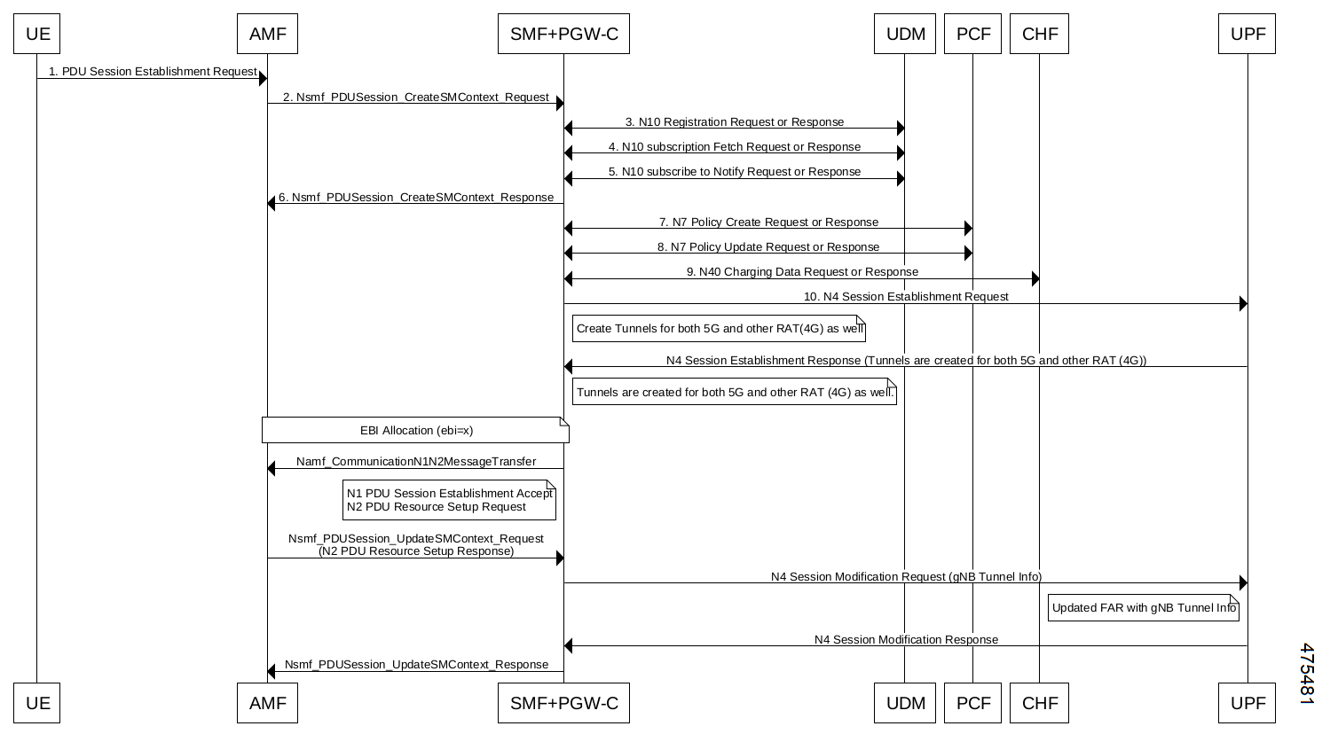
The UE initiates the UE Requested PDU Session Establishment procedure by transmitting a NAS message containing a PDU Session Establishment Request within the N1 SM container. The PDU Session Establishment Request includes a PDU session ID, Requested PDU Session Type, a Requested SSC mode, 5GSM Capability PCO, SM PDU DN Request Container, Number of Packet Filters, and optionally Always-on PDU Session Requested.
2 The AMF performs SMF selection as described in 3GPP specification.
3 The AMF includes EPS Interworking Indication in the Nsmf_PDUSession_CreateSMContext Request message sent to the SMF. This parameter indicates whether the UE can perform 4G to 5G handover (and vice versa) and if it is allowed with or without the presence of the N26 interface between the AMF and MME.
4 If the EPS Interworking Indication received from the AMF indicates that the UE supports EPS interworking and the SMF determines (for example, if EPS interworking is allowed for this DNN and S-NSSAI based on UE subscription data) that the PDU session supports EPS interworking, the PGW-C+SMF FQDN for the S5/S8 interface is included in the Nudm_UECM_Registration Request message.
5

The SMF sends either Nsmf_PDUSession_CreateSMContext Response (Cause, SM Context ID or N1 SM container (PDU Session Reject (Cause))) or an Nsmf_PDUSession_UpdateSMContext Response depending on the Request received in Step 3.

If the SMF received Nsmf_PDUSession_CreateSMContext Request in Step 3 and the SMF can process the PDU Session Establishment Request, the SMF creates an SM context and responds to the AMF by providing an SM Context Identifier.

6

(Optional). If the Request Type in Step 3 indicates "Existing PDU Session", the SMF does not perform secondary authorization and authentication.

If the Request Type received in Step 3 indicates "Emergency Request" or "Existing Emergency PDU Session", the SMF does not perform secondary authorization and authentication.

If the SMF needs to perform secondary authorization and authentication during the establishment of the PDU Session by a DN-AAA server as described in 3GPP TS 23.501, section 5.6.6, the SMF triggers the PDU session establishment authentication and authorization as described in 3GPP TS 23.501, section 4.3.2.3.

7a If dynamic PCC is to be used for the PDU Session, the SMF performs PCF selection as described in 3GPP TS 23.501, section 6.3.7.1. If the Request Type indicates "Existing PDU Session" or "Existing Emergency PDU Session", the SMF uses the PCF already selected for the PDU Session. Otherwise, the SMF may apply local policy.
7b The SMF performs the mapping of PCC rules and 5G QoS parameters to 4G TFTs and 4G QoS as described in the Generating EPS PDN Connection Parameters from 5G PDU Session Parameters section in this document. Based on the QoS flows, the SMF+PGW-C also determines the number of dedicated bearers required for the session when it hands off to EPS and the required flows (all non-GBR flows) in the default bearer. The SMF+PGW-C saves the mapping of 5G flows to 4G bearers.
8 If the Request Type in Step 3 indicates "Initial request", the SMF selects an SSC mode for the PDU Session as described in 3GPP TS 23.501, section 5.6.9.3. The SMF also selects one or more UPFs as needed as described in 3GPP TS 23.501, section 6.3.3.
9

The SMF performs an SMF-initiated SM Policy Association Modification procedure as defined in 3GPP TS 23.502, section 4.16.5.1 to provide information on the Policy Control Request Trigger conditions that have been met. If Request Type is "initial request" and dynamic PCC is deployed and PDU Session Type is IPv4 or IPv6 or IPv4v6, the SMF notifies the PCF (if the Policy Control Request Trigger condition is met) with the allocated UE IP address/prefix(es).

SMF+PGW-C initiates the EBI allocation procedure as defined in 3GPP TS 23.502, section 4.11.1.4.

10

If the Request Type indicates "initial request", the SMF initiates an N4 Session Establishment procedure with the selected UPF. Otherwise, it initiates an N4 Session Modification procedure with the selected UPF.

If multiple UPFs are selected for the PDU Session, the SMF initiates N4 Session Establishment/Modification procedure with each UPF of the PDU Session in this step.

11 In the non-roaming or LBO scenario, the PGW-C+SMF includes the mapped EPS bearer context(s) and the corresponding QoS flow(s) to be sent to the UE in the N1 SM container. The PGW-C+SMF also indicates the mapping between the QoS flow(s) and mapped EPS bearer context(s) in the N1 SM container. The PGW-C+SMF also includes the mapping between the received EBI(s) and QFI(s) in the N2 SM information to be sent to the NG-RAN. The PGW-C+SMF sends the N1 SM container and N2 SM information to the AMF through the Namf_Communication_N1N2MessageTransfer message.
12

The AMF sends N2 PDU Session Request (N2 SM information, NAS message (PDU Session ID, N1 SM container (PDU Session Establishment Accept))) to the (R)AN.

The AMF sends the NAS message containing PDU Session ID and PDU Session Establishment Accept targeted to the UE and the N2 SM information received from the SMF within the N2 PDU Session Request to the (R)AN.

13 The (R)AN may issue AN-specific signaling exchange with the UE that is related with the information received from the SMF. For example, in case of an NG-RAN, an RRC Connection Reconfiguration may take place with the UE establishing the necessary NG-RAN resources related to the QoS rules for the PDU Session Request received in Step 12.
14 (R)AN issues N2 PDU Session Response (PDU Session ID, Cause, N2 SM information (PDU Session ID, AN Tunnel Info, List of accepted/rejected QFI(s), User Plane Enforcement Policy Notification)) to the AMF.
15

The AMF sends Nsmf_PDUSession_UpdateSMContext Request (N2 SM information, Request Type) to the SMF.

The AMF forwards the N2 SM information received from (R)AN to the SMF.

16a The SMF initiates an N4 Session Modification procedure with the UPF. The SMF provides AN Tunnel Information and the corresponding forwarding rules to the UPF.
16b

The UPF provides an N4 Session Modification Response to the SMF.

If multiple UPFs are used in the PDU session, the UPF in Step 16a refers to the UPF terminating N3.

After this step, the UPF delivers any downlink packets to the UE that may have been buffered for this PDU session.

17 The SMF sends Nsmf_PDUSession_UpdateSMContext Response (Cause) to the AMF.
18

(Conditional) The SMF sends Nsmf_PDUSession_SMContextStatusNotify (Release) to the AMF.

If during the procedure, any time after Step 5, the PDU Session establishment is not successful, the SMF informs the AMF by invoking Nsmf_PDUSession_SMContextStatusNotify (Release). The SMF also releases any N4 session(s) created, any PDU session address if allocated (for example, IP address) and releases the association with PCF, if any.

19 If the PDU Session Type is IPv6 or IPv4v6, the SMF generates an IPv6 Router Advertisement and sends it to the UE via N4 and the UPF.
20

If the PDU Session Establishment failed after Step 4, the SMF performs the following:

  • The SMF unsubscribes to the modifications of Session Management Subscription data for the corresponding (SUPI, DNN, S-NSSAI), using Nudm_SDM_Unsubscribe (SUPI, Session Management Subscription data, DNN, S-NSSAI), if the SMF is no more handling a PDU session of the UE for this (DNN, S-NSSAI). The UDM may unsubscribe to the modification notification from UDR by Nudr_DM_Unsubscribe (SUPI, Subscription Data, Session Management Subscription data, S-NSSAI, DNN).

  • The SMF deregisters for the given PDU session using Nudm_UECM_Deregistration (SUPI, DNN, PDU Session ID). The UDM may update corresponding UE context by Nudr_DM_Update (SUPI, Subscription Data, UE context in SMF data).

PDU Session Modification Call Flow

This section describes the PDU session modification procedure as specified in 3GPP TS 23.502, section 4.3.3.2.

Figure 36. PDU Session Modification Call Flow
Table 29. PDU Session Modification Call Flow Description
Step Description

1a

The UE initiates the UE Requested PDU Session Modification procedure by transmitting a NAS message containing a PDU Session Modification Request within the N1 SM container. The PDU Session Modification Request includes a PDU session ID, Packet Filters, Operation, Requested QoS, Segregation, and 5GSM Core Network Capability.

1b

(SMF-requested modification) The PCF performs a PCF-initiated SM Policy Association Modification procedure to notify the SMF about the modification of policies. The policy decision or upon AF requests, for example, Application Function influence on traffic routing, triggers this procedure.

1c

(SMF-requested modification) The UDM updates the subscription data of SMF by Nudm_SDM_Notification (SUPI, Session Management Subscription Data). The SMF updates the Session Management Subscription Data and acknowledges the UDM by returning an Ack with (SUPI).

1d

(SMF-requested modification) The SMF decides to modify PDU session. This procedure is also triggered based on locally configured policy or triggered from the (R)AN.

If the SMF receives one of the triggers in step 1b to 1d, the SMF starts SMF-requested PDU Session Modification procedure.

1e

(AN-initiated modification) (R)AN indicates to the SMF when the AN resources onto which a QoS Flow is mapped are released irrespective of whether notification control is configured.

(R)AN sends the N2 message (PDU Session ID, N2 SM information) to the AMF. The N2 SM information in the smf_PDU_Session_UpdateContext includes the following information:

  • QoS Flow Identifier (QFI)

  • User location Information

  • QoS Flow Release List IE - list of QoS flows which are released by NG-RAN node

  • QoS Flow Notify List IE and Notification Cause IE - list of GBR QoS flows that fulfilled a specific criteria, and the flows that missed fulfilling the criteria

The SMF supports AN-initiated modification to release the QFI from RAN. For details on this support, see the following section.

2

The SMF reports the subscribed event to the PCF by performing an SMF-initiated SM Policy Association Modification procedure. The SMF skips this step if the PDU Session Modification procedure is triggered by step 1b or 1d. If the dynamic PCC is not deployed, the SMF may apply local policy to decide whether to change the QoS profile. The SMF does not invoke the steps 3 to 7 when the PDU Session Modification requires only action at a UPF (for example, gating).

3a

For UE or AN-initiated modification, the SMF responds to the AMF through Nsmf_PDUSession_UpdateSMContext including N2 SM information and N1 SM container.

The N2 SM information carries information that the AMF provides to the (R)AN. It includes the QoS profiles and the corresponding QFIs to notify the (R)AN that one or more QoS flows were added, or modified. It includes only QFI(s) to notify the (R)AN that one or more QoS flows were removed.

The N1 SM container carries the PDU Session Modification Command that the AMF provides to the UE. It includes the QoS rule(s), QoS rule operation, QoS Flow level QoS parameters if needed for the QoS Flow(s) associated with the QoS rule(s), and Session-AMBR.

3b

For SMF-requested modification, the SMF invokes Namf_Communication_N1N2MessageTransfer including N2 SM information and N1 SM container.

If the UE is in CM-IDLE state and an Asynchronous type communication (ATC) is activated, the AMF updates and stores the UE context based on the Namf_Communication_N1N2MessageTransfer, and skips the steps 4, 5, 6 and 7. When the UE is reachable, that is, when the UE enters CM-CONNECTED state, the AMF forwards the N1 message to synchronize the UE context with the UE.

4

The AMF sends N2 PDU Session Request (N2 SM information received from the SMF, NAS message (PDU Session ID, N1 SM container (PDU Session Modification Command))) Message to the (R)AN.

5

The (R)AN issues AN-specific signalling exchange with the UE that is related with the information received from the SMF. For example, in an NG-RAN, an RRC Connection Reconfiguration takes place with the UE modifying the necessary (R)AN resources related to the PDU session.

6

The (R)AN acknowledges N2 PDU Session Request by sending a N2 PDU Session Ack Message to the AMF.

7

The AMF forwards the N2 SM information and the User location Information from the AN to the SMF via Nsmf_PDUSession_UpdateSMContext service operation. The SMF sends Nsmf_PDUSession_UpdateSMContext Response.

If the (R)AN rejects QFI(s), the SMF updates the QoS rules and QoS Flow level QoS parameters if needed for the QoS Flow(s) associated with the QoS rule(s) in the UE accordingly.

8

The SMF updates N4 session of the UPF(s) that are involved by the PDU Session Modification by sending N4 Session Modification Request message to the UPF.

9

The UE acknowledges the PDU Session Modification Command by sending a NAS message (PDU Session ID, N1 SM container (PDU Session Modification Command Ack)).

10

The (R)AN forwards the NAS message to the AMF.

11

The AMF forwards the N1 SM container (PDU Session Modification Command Ack) and User Location Information from the AN to the SMF through Nsmf_PDUSession_UpdateSMContext service operation. The SMF sends Nsmf_PDUSession_UpdateSMContext Response.

12

The SMF updates N4 session of the UPF(s) that are involved by the PDU Session Modification by sending N4 Session Modification Request (N4 Session ID) message to the UPF.

For a PDU Session of Ethernet PDU Session Type, the SMF notifies the UPF to add or remove Ethernet Packet Filter Set(s) and forwarding rule(s).

13

If the SMF interacts with the PCF in step 1b or 2, the SMF notifies the PCF whether the PCC decision is enforced or not by performing an SMF-initiated SM Policy Association Modification procedure.

The SMF notifies any entity that has subscribed to User Location Information related with PDU Session change.

If the step 1b is triggered to perform Application Function influence on traffic routing, the SMF reconfigures the User Plane of the PDU session.

Releasing QFI During AN-initiated Modification Procedure

For the SMF to support AN-initiated modification to release the QFIs, perform the following steps:

  1. If the EPS Interworking Indication is enabled for a given PDU session, the SMF initiates the EBI release towards the AMF.

  2. The SMF sends N4 Modification to the UPF to delete the Packet Detection Rule (PDR), QoS Enforcement Rule (QER), and Usage Reporting Rule (URR) related to the flows being released.

  3. The SMF initiates N1N2TransferMessage containing N1 PDU Session Modification command. This message includes information about the deleted flows, Mapped EPS Bearer Context.

  4. Then, the SMF interacts with the PCF to report the flows released for the rules if “RES_RELEASE” trigger is set.


Note


The "policy_pdu_flows_total" statistics is available to check the released flows.


EPS Interworking Indication in PDU Session Modification

The EpsInternetworkingIndication field denotes the possibility of handover between EPS and 5GC. This field holds the following values:

  • NONE: The PDU session cannot be moved to EPS.

  • WITH_N26: The PDU session is moved to EPS, with N26 interface supported during EPS interworking procedures.

  • WITHOUT_N26: The PDU session is moved to EPS, without N26 interface supported during EPS interworking procedures.

The SMF allows the 4G to 5G handover and vice-versa only if the EpsInternetworkingIndication value is set to WITH_N26. For other values of EpsInternetworkingIndication, the SMF rejects the handovers.

During 4G and 5G PDU session establishment, if the EPS internetworking indication is received from the AMF, the SMF includes PGW-C+SMF FQDN for S5/S8 interface in the UDM Registration request.

With the EPS Interworking Indication Support Enabled:

If the EpsInternetworkingIndication value changes from NONE or WITHOUT_N26 to WITH_N26 for a created PDU session, follow these steps to support the EPS Interworking Indication change in the PDU modification procedure.

  1. The AMF invokes the Nsmf_PDUSession_UpdateSMContext request with the changed EpsInterworkingIndication value.

  2. The SMF receives the Nsmf_PDUSession_UpdateSMContext request from the AMF, and initiates the Namf_Communication_EbiAssignmentRequest. This request includes the PDU Session ID and Allocation/Retention Priority (ARP) List.

  3. The AMF sends Namf_Communication_EbiAssignmentResponse to the SMF. The AMF sends the following through the response:

    • assignedEbiList containing the successfully assigned EBIs.

    • failedArpList containing the failed ARPs for which the EBI assignment failed.

    • 4XX/5XX error along with AssignEbiError representing the EBI assignment failure.

  4. The SMF sends N1N2MessageTransfer request message if the EBIs are created successfully. This request includes the following:

    • N1:PDU SESSION MODIFICATION COMMAND ([Mapped EPS Bearer Contexts,Create])

    • N2:N2_PDU_SESSION_RESOURCE_MODIFY_REQUEST_TRANSFER (QoS Flow Add or Modify Request Item with EPS Radio Access Bearer (E-RAB) ID and QoS Flow ID)


    Note


    If the UE is in Idle mode, the SMF skips sending the N2 message.


  5. The SMF informs mapped EPS bearer context in the UE using N1 message. The SMF waits for N1: PDU SESSION MODIFICATION COMPLETE message.

  6. The SMF informs EBI to QoS Flow Identifier (QFI) mapping to gNodeB using N2 message. The SMF waits for N2: PDU SESSION RESOURCE MODIFY RESPONSE TRANSFER message.

  7. The SMF completes the PDU Session Modification procedure.

With the EPS Interworking Indication Support Disabled:

If the EpsInternetworkingIndication value changes from WITH_N26 to NONE or WITHOUT_N26 for a created PDU session, follow these steps to support the EPS Interworking Indication change in the PDU modification procedure.

  1. The SMF receives the Nsmf_PDUSession_UpdateSMContext request with the changed EpsInterworkingIndication value from the AMF.

  2. The SMF sends N1N2MessageTransfer request message. This request includes the following:

    • N1:PDU SESSION MODIFICATION COMMAND ([Mapped EPS Bearer Contexts,Delete])

    • N2:N2_PDU_SESSION_RESOURCE_MODIFY_REQUEST_TRANSFER


    Note


    If the UE is in Idle mode, the SMF skips sending the N2 message.


  3. The SMF deletes Mapped EPS bearer context in UE using N1 message. The SMF waits for N1: PDU SESSION MODIFICATION COMPLETE message.

  4. The SMF deletes EBI to QFI mapping to gNodeB using N2 message. The SMF waits for N2: PDU SESSION RESOURCE MODIFY RESPONSE TRANSFER message.

  5. The SMF completes the PDU Session Modification procedure.

Use the show subscriber command to determine the EPS interworking status of the PDU session, and the EBI mapping for the QoS flows.

PDU Session Release Call Flow

The PDU Session Release procedure is used to release all the resources associated with a PDU session, including:

  • The IP address/prefixes allocated for an IP-based PDU session

  • Any UPF resource that was used by the PDU session.

  • Any access resource that was used by the PDU session.

The SMF notifies any entity associated with the PDU session: PCF, Data Network (DN) (for example, when DN authorization has taken place at PDU session establishment), and so on.

There are different ways to initiate the PDU session release. It can be from UE, network, AMF, or RAN.

UE-initiated PDU Session Release Call Flow

The UE-initiated PDU session release procedure allows the UE to request the release of the PDU session. In the case of Local Breakout (LBO), the procedure is as in the case of non-roaming with the difference that the AMF, the SMF, the UPF, and the PCF are located in the visited network.

The following figure depicts the UE-initiated PDU session release procedure to support EPS interworking on the SMF as specified in 3GPP TS 23.502, section 4.3.4.2.

Figure 37. UE-initiated PDU Session Release Call Flow
Table 30. UE-initiated PDU Session Creation Call Flow Description
Step Description

1, 2

The UE sends PDU_SESSION_RELEASE_REQUEST in NAS message to the AMF through the RAN. The AMF sends the message to the SMF in SmContextUpdateRequest.

3, 4

The SMF sends N4SessionReleaseRequest to the UPF. The UPF sends response for the same.

5

The SMF sends SmContextUpdateResponse message with N1 and N2 content.

  • N1: PDU_SESSION_RELEASE_COMMAND

  • N2: N2_PDU_SESSION_RESOURCE_RELEASE_COMMAND. exclude if the SMF is in IDLE mode. Also, skip the steps 8, 9, and 10.

6, 7

The AMF exchanges the message with RAN. The RAN forwards it to the UE.

8, 9, 10

The RAN sends N2 release response to the AMF. The AMF sends N2 release response (N2_PDU_SESSION_RESOURCE_RELEASE_RESPONSE_TRANSFER) in N11 SmContextUpdateRequest message. The SMF responds back to the AMF as SmContextUpdateResponse.

11, 12, 13, 14

The UE sends N1 release response in NAS message to the AMF through the RAN. The AMF sends N1 release response (PDU_SESSION_RELEASE_COMPLETE) in N11 SmContextUpdateRequest message. The SMF responds back to the AMF as SmContextUpdateResponse.

15, 16

The SMF sends delete charging request to the CHF. The CHF responds back to the SMF with delete response.

17, 18

The SMF sends SmContextStausNotify to the AMF. The AMF responds back with SmContextStausNotifyResponse message.

19, 20

The SMF sends delete request to the PCF. The PCF responds back to the SMF with delete response

21, 22

The SMF sends UDM deregistration request. The UDM responds back to the SMF with deregistration response.

Network-initiated PDU Session Release Call Flow

The network-initiated PDU session release procedure allows the AMF, the SMF or the PCF to initiate the release of a PDU session.

The following figure depicts the network-initiated PDU session release call flow.

Figure 38. Network-initiated PDU Session Release Call Flow
Table 31. Network-initiated PDU Session Creation Call Flow Description
Step Description
1

This procedure can be triggered by PCF, CHF, UDM, UPF or CLI (clear subscriber) to initiate the release of a PDU session.

2, 3

The SMF sends N4SessionReleaseRequest to the UPF. The UPF sends response for the same.

Note


Skip the steps 4 to 14 if the AMF has notified that the UE is not reachable.

4

The SMF sends N1N2MessageTransfer message with N11, N1 and N2 content.

  • N11: SkipInd=True

  • N1: PDU_SESSION_RELEASE_COMMAND

  • N2: N2_PDU_SESSION_RESOURCE_RELEASE_COMMAND. exclude if the SMF is in IDLE mode. Also, skip the steps 8, 9, and 10.

5

The AMF responds back to the SMF with the cause included in the N1N2MessageTransferRsp message.

Note


Skip the steps 6 to 14 if the AMF sends the cause as N1_MSG_NOT_TRANSFERRED in step 5.

6, 7

The AMF exchanges the message with RAN. The RAN forwards it to the UE.

8, 9, 10

The RAN sends N2 release response to the AMF. The AMF transfers N2 release response (N2_PDU_SESSION_RESOURCE_RELEASE_RESPONSE_TRANSFER) in N11 SmContextUpdateRequest message. The SMF responds back to the AMF as SmContextUpdateResponse.

11, 12, 13, 14

The UE sends N1 release response in the NAS message to the AMF through the RAN. The AMF sends the N1 release response (PDU_SESSION_RELEASE_COMPLETE) in N11 SmContextUpdateRequest message. The SMF responds back to the AMF as SmContextUpdateResponse.

15, 16

The SMF sends delete charging request to the CHF. The CHF responds back to the SMF with delete response.

17, 18

The SMF sends SmContextStausNotify to the AMF. The AMF responds back with the SmContextStausNotifyResponse message.

19, 20

The SMF sends delete request to the PCF. The PCF responds back to the SMF with delete response.

21, 22

The SMF sends UDM deregistration request. The UDM responds back to the SMF with deregistration response.

AMF-initiated PDU Session Release

The AMF-initiated PDU session release procedure allows the AMF to initiate the release of a PDU session.

The following figure depicts the AMF-initiated PDU session release call flow.

Figure 39. AMF-initiated PDU Session Release Call Flow
Table 32. AMF-initiated PDU Session Creation Call Flow Description
Step Description
1

The AMF sends SmContextReleaseRequest.

2, 3

The SMF sends N4SessionReleaseRequest to the UPF. The UPF sends response for the same.

4

The SMF sends SmContextReleaseResponse to the AMF.

5, 6

The SMF sends delete charging request to the CHF. The CHF responds back to the SMF with delete response.

7, 8

The SMF sends delete request to the PCF. The PCF responds back to the SMF with delete response.

9, 10

The SMF sends UDM deregistration request. The UDM responds back to the SMF with deregistration response.

AMF-initiated PDU Session Release with N11 Release=True

The AMF-initiated PDU session release procedure allows the AMF to initiate the release of a PDU session with the N11 release in the SmContextModifyRequest being set to True.

The following figure depicts the AMF-initiated PDU session release call flow with the N11 release=True.

Figure 40. AMF-initiated PDU Session Release with N11 Release=True
Table 33. AMF-initiated PDU Session Creation Call Flow (N11 release=true) Description
Step Description
1

The AMF sends SmContextModifyRequest with release=True in 2 causes REL_DUE_TO_DUPLICATE_SESSION_ID or REL_DUE_TO_SLICE_NOT_AVAILABLE.

2, 3

The SMF sends N4SessionReleaseRequest to the UPF. The UPF sends response for the same.

4

The SMF sends SmContextUpdateResponse message with N1 and N2 content.

  • N1: PDU_SESSION_RELEASE_COMMAND, exclude if cause is REL_DUE_TO_DUPLICATE_SESSION_ID, skip steps 10,11,12,13

  • N2: N2_PDU_SESSION_RESOURCE_RELEASE_COMMAND. exclude if the SMF is in IDLE mode. Also, skip the steps 7, 8, and 9.

5, 6

The AMF exchanges message with RAN. The RAN forwards it to the UE.

7, 8, 9

The RAN sends N2 release response to the AMF. The AMF sends N2 release response (N2_PDU_SESSION_RESOURCE_RELEASE_RESPONSE_TRANSFER) in N11 SmContextUpdateRequest message. The SMF responds back to the AMF as SmContextUpdateResponse.

10, 11, 12, 13

The UE sends N1 release response in NAS message to the AMF through the RAN. The AMF sends N1 release response (PDU_SESSION_RELEASE_COMPLETE) in N11 SmContextUpdateRequest message. The SMF responds back to the AMF as SmContextUpdateResponse.

14, 15

The SMF sends delete charging request to the CHF. The CHF responds back to the SMF with delete response.

16, 17

The SMF sends SmContextStausNotify to the AMF. The AMF responds back with SmContextStausNotifyResponse message.

18, 19

The SMF sends delete request to the PCF. The PCF responds back to the SMF with delete response.

20, 21

The SMF sends UDM deregistration request. The UDM responds back to the SMF with deregistration response.

RAN-initiated PDU Session Release Call Flow

The RAN-initiated PDU session release procedure allows the RAN to initiate the release of a PDU session.

The following figure depicts the RAN-initiated PDU session release call flow.

Figure 41. RAN-initiated PDU Session Release Call Flow
Table 34. AMF-initiated PDU Session Creation Call Flow Description
Step Description
1

The AMF sends SmContextModifyRequest with N2 type: N2_PDU_SESSION_RESOURCE_NOTIFY_RELEASED_TRANSFER.

2, 3

The SMF sends N4SessionModificationRequest to the UPF with changing packet rule to Buffer from Forward. The UPF sends the response for the same, that is, the SMF moving to IDLE state.

4

The SMF sends SmContextUpdateResponse message with UpState as Deactivated.

EPS Bearer ID Allocation

This section describes the EPS Bearer ID Allocation procedure.

Figure 42. EPS Bearer ID Allocation Call Flow

Note


Not all the steps in the preceding call flow are supported. For more details, see the descriptions in the following table.
Table 35. EPS Bearer ID Allocation Call Flow Description
Step Description
1 If the PGW-C+SMF (or H-SMF for home-routed cases) determines that EPS bearer IDs (based on operator policies, S-NSSAI, User Plane Security Enforcement information) need to be assigned to the QoS flows in the PDU session, the PGW-C+SMF invokes Namf_Communication_EBIAssignment Request (PDU Session ID, ARP list).
Step 2 through Step 5 apply only when the AMF needs to revoke EBI that was previously allocated for a UE to serve a new SMF request of EBI for the same UE.
2 (Conditional) If the AMF has no available EBIs, the AMF may revoke an EBI that was assigned to QoS flows based on the ARPs and S-NSSAI stored during PDU Session Establishment, EBI information in the UE context and local policies. If an assigned EBI is to be revoked, the AMF invokes Nsmf_PDUSession_UpdateSMContext (EBI(s) to be revoked) to request the related SMF (called “SMF serving the released resources”) to release the mapped EPS QoS parameters corresponding to the EBI to be revoked. The AMF stores the association of the assigned EBI, ARP pair to the corresponding PDU Session ID and SMF address.
3

The “SMF serving the released resources” that receives the request in Step 3 invokes Namf_Communication_N1N2Message Transfer (N2 SM information (PDU Session ID, EBI(s) to be revoked), N1 SM container (PDU Session Modification Command (PDU Session ID, EBI(s) to be revoked))) to inform the (R)AN and the UE to remove the mapped EPS QoS parameters corresponding to the EBI(s) to be revoked. In home-routed roaming scenario, the H-SMF includes EBI(s) to be revoked to V-SMF to inform V-SMF to remove the mapped EPS bearer context corresponding to the EBI(s) to be revoked.

The SMF can also decide to remove the QoS flow if it is not acceptable to continue the service when no corresponding EPS QoS parameters can be assigned.

For home-routed roaming scenario, the "SMF serving the released resources" sends an N4 Session Modification Request to request the PGW-U+UPF to release the N4 session corresponding to the revoked EBI(s).

In home-routed roaming case, the V-SMF starts a VPLMN-initiated QoS Modification for the PDU session. The V-SMF invokes the Namf_Communication_N1N2Message Transfer based on the corresponding QoS modification message received from H-SMF.

4

If the UE is in CM-CONNECTED state, the AMF sends N2 PDU Session Request (N2 SM information received from SMF, NAS message (PDU Session ID, N1 SM container (PDU Session Modification Command))) message to the (R)AN.

If the UE is in CM-IDLE state and an ATC is activated, the AMF updates and stores the UE context based on the Namf_Communication_N1N2MessageTransfer and Step 5 and Step 6 are skipped. When the UE is reachable, for example, when the UE enters CM-CONNECTED state, the AMF forwards the N1 message to synchronize the UE context with the UE.

5 The relevant steps of the procedure are executed as specified in the preceding figure.
6

If the AMF successfully assigns EBI(s), it responds with the assigned EBI(s). Otherwise, it responds with a cause indicating EBI assignment failure.

If a PDU session from another SMF already exists towards the same DNN, the AMF either rejects the EBI assignment request, or revokes the EBI(s) from the existing PDU session(s) to the same DNN but different SMF. The AMF makes the decision based on the operator policy.

Note


The preceding statement applies only when the S-NSSAI(s) for the PDU sessions are different, otherwise the same SMF is selected for PDU sessions to the same DNN.

7

The PGW-C+SMF sends an N4 Session Establishment/Modification Request to the PGW-U+UPF.

For home-routed roaming scenario, if the EBI is assigned successfully, the PGW-C+SMF prepares the CN Tunnel Info for each EPS bearer. If the CN Tunnel info is allocated by the PGW-C+SMF, the PGW-U tunnel info for the EPS bearer may be provided to PGW-U+UPF. If the CN Tunnel info is allocated by PGW-U+UPF, the PGW-U+UPF sends the PGW-U tunnel info for the EPS bearer to the PGW-C+SMF. The PGW-U+UPF is ready to receive the uplink packets from E-UTRAN.

Note

 
  • In the home-routed roaming scenario, the PGW-C+SMF prepares the CN Tunnel Info for each EPS bearer and provides it to the V-SMF. Thus, when the UE moves to EPS network, the V-SMF does not need to interact with the PGW-C+SMF to get the EPS bearer context(s).

  • If the CN Tunnel info is allocated by the PGW-C+SMF and not provided to PGW-U+UPF at PDU session establishment, when the UE moves to the target RAT the PGW-U+UPF cannot receive uplink (UL) data until the PGW-C+SMF has provided the Tunnel Info to the PGW-U+UPF in N4 Session Modification. This causes a short interruption to the UL data during the inter-system handover execution.

  • SMF supports other RAT tunnel creation for EPS bearers during 5G PDU establishment and in the 5G PDU modification (new flow creation time). SMF sends the additional PDRs for EPS bearers in the N4 establishment and the N4 modification requests to communicate to UPF on these additional tunnel creation for the EPS bearers.

8

If the PGW-C+SMF receives any EBI(s) from the AMF, it adds the EBI(s) received into the mapped EPS bearer context(s).

In home-routed roaming scenario, the PGW-C+SMF generates EPS bearer context, which includes per EPS bearer PGW-U tunnel information. In addition, if the default EPS bearer is generated for the corresponding PDN Connection of PDU Session (that is, during the PDU Session establishment procedure), the PGW-C+SMF generates the PGW-C tunnel information of the PDN connection and includes it in UE EPS PDN connection.

8a (Conditional) In non-roaming or LBO scenario, the PGW-C+SMF includes the mapped EPS bearer context(s) and the corresponding QoS Flow(s) to be sent to the UE in the N1 SM container. PGW-C+SMF also indicates the mapping between the QoS flow(s) and mapped EPS bearer context(s) in the N1 SM container. PGW-C+SMF also includes the mapping between the received EBI(s) and QFI(s) in the N2 SM information to be sent to the NG-RAN. The PGW-C+SMF sends the N1 SM container and N2 SM information to the AMF via Namf_Communication_N1N2MessageTransfer.
8b (Conditional) In home-routed roaming scenario, the PGW-C+SMF sends the mapped EPS bearer context(s), the mapping between the received EBI(s) and QFI(s), and EPS bearer context to the V-SMF via Nsmf_PDUSession_Create Response during PDU Session Establishment, or via Nsmf_PDUSession_Update Request during PDU Session Modification. The V-SMF stores the EPS bearer context, and generates N1 SM container and N2 SM information, and forwards them to the AMF via Namf_Communication_N1N2MessageTransfer.
9 The N1 SM container and N2 SM information are sent to the UE and NG-RAN respectively. The relevant steps of the procedure are executed as specified in the preceding figure.
Non-roaming 5G PDU Establishment with N4 Optimization Call Flow

This section describes the call flow of the non-roaming 5G PDU establishment with N4 optimization.

Figure 43. Non-roaming 5G PDU Establishment with N4 Optimization Call Flow
Table 36. Non-roaming 5G PDU Establishment with N4 Optimization Call Flow Description
Step Description
1

UE sends the PDU session establishment request to AMF.

2 AMF sends the Nsmf PDU session CreateSMContext request to SMF+PGW-C.
3 SMF+PGW-C sends the N10 Registration Request to UDM. Then, UDM sends the N10 Registration Response to SMF+PGW-C.
4

SMF+PGW-C sends the N10 Subscription Fetch Request to UDM. Then, UDM sends the N10 Subscription Fetch Response to SMF+PGW-C.

5

SMF+PGW-C sends the N10 Subscribe to Notify Request to UDM. Then, UDM sends the N10 Subscribe to Notify Response to SMF+PGW-C.

6

SMF+PGW-C sends the Nsmf PDU Session CreateSMContext Response to AMF.

7

SMF+PGW-C sends the N7 Policy Create Request to PCF. Then, PCF sends the N7 Policy Create Response to SMF+PGW-C.

8

SMF+PGW-C sends the N7 Policy Update Request to PCF. Then, PCF sends the N7 Policy Update Response to SMF+PGW-C.

9

SMF+PGW-C sends the N40 Charging Data Request to CHF. Then, CHF sends the N40 Charging Data Response to SMF+PGW-C.

10

SMF+PGW-C sends the N4 Session Establishment Request to UPF. SMF creates a tunnel for both 5G and other RAT (4G).

11

After the creation of the tunnel, UPF sends the N4 Session Establishment Response to SMF+PGW-C.

12

SMF+PGW-C initiates the EBI allocation procedure. Then, SMF+PGW-C sends the Namf Communication N1N2Message Transfer request to AMF.

13

After the N1 PDU Session Establishment is accepted and the N2 PDU Resource Setup Request is sent, SMF+PGW-C sends the Nsmf PDU Session UpdateSMContext Request (N2 PDU Resource Setup Response) to SMF+PGW-C.

14

SMF+PGW-C sends the N4 Session Modification Request to UPF. This request includes the gNB tunnel details.

15

UPF sends the N4 Session Modification Response to SMF+PGW-C. The response includes the updated FAR and the gNB tunnel details.

16

SMF+PGW-C sends the Nsmf PDU Session UpdateSMContext Response to AMF.

Standards Compliance

This feature complies with the following standards:

  • 3GPP TS 23.401, Version 15.6.0

  • 3GPP TS 23.502, Version 15.4.0

Generating EPS PDN Connection Parameters from 5G PDU Session Parameters

This section describes how to generate the EPS PDN connection parameters from the 5G PDU session parameters in the PGW-C+SMF.

When the PGW-C+SMF is requested to set up or modify a PDN connection or a PDU session that supports interworking between EPS and 5GC, the PGW-C+SMF generates the PDN connection parameters from the PDU session parameters.

When the PGW-C+SMF generates the PDN connection parameters based on the PDU session parameters, the following rules hold:

  • PDN Type: The PDN type is set to IPv4 or IPv6 if the PDU Session Type is IPv4 or IPv6 respectively. The PDN type is set to Non-IP for Ethernet and Unstructured PDU Session Types.

  • EPS Bearer ID: The EBI is requested from the AMF during the establishment of a QoS Flow as described in 3GPP TS 23.502, section 4.11.1.4.1, for PDU sessions that support interworking between EPS and 5GC. The EBI is obtained from MME during the establishment of an EPS bearer (that is triggered by an establishment of the QoS Flow) as defined in 3GPP TS 23.401 for PDN connections hosted by PGW-C+SMF. The association between EBI and QoS Flow is stored by the SMF.

  • APN-AMBR: APN-AMBR is set according to the operator policy. For example, taking the session AMBR into account.

  • EPS QoS parameters (including ARP, QCI, GBR, and MBR):

    • If the QoS Flow is mapped to one EPS bearer: ARP, GBR, and MBR of the EPS bearer is set to the respective ARP, GFBR, and MFBR of the corresponding QoS Flow.

    • For standardized 5QIs, the QCI is mapped 1:1 to the 5QI. For non-standardized 5QIs, the PGW-C+SMF derives the QCI based on the 5QI and operator policy.


Note


A GBR QoS flow is mapped 1:1 to a GBR dedicated EPS Bearer if an EBI has been assigned. All other GBR QoS flows will be terminated during interworking. If multiple QoS flows are mapped to one EPS bearer, the EPS bearer parameters are set based on the operator policy. For example, EPS bearer QoS parameters are set according to the highest QoS of all mapped QoS flows.


Note


Non-GBR QoS flows for which no EBI has been assigned are mapped to the default EPS bearer.


5G to EPS Handover Using N26 Interface

Feature Description

The SMF supports handover of PDU sessions to EPS on 5GC when the N26 interface is present between the MME and the AMF. The handover supports the creation of applicable default and dedicated bearers.

How it Works

This section describes the 5G to EPS handover procedure and the 5G to EPS handover cancellation procedure.

Call Flows

This section describes the following call flows:

  • 5G to EPS Handover Call Flow

  • 5G to EPS Handover Cancellation Flow

5G to EPS Handover Call Flow

This section describes the 5G to EPS handover call flow with N26 interface.

The 5G to EPS Handover procedure for the EPS session is compliant with 3GPP 23.502, section 4.11.1.2.1.

  1. The AMF requests the SMF to provide the SM Context using Nsmf_PDUSession_ContextRequest.

  2. The SMF sends N4 Session Modification to the UPF to establish the CN tunnel for each EPS bearer. The bearer mapping to the 5G QoS and PCC rules received from PCC must already be present with the SMF. The SMF must also have the bearer IDs obtained from the Bearer ID Allocation procedure. The SMF creates new PDRs for the N4 session and gets TEID allocated for each bearer as required by the 4G system.

  3. The SMF provides EPS bearer contexts to the AMF. The SMF also provides the CN tunnel information to AMF for all bearers for the uplink traffic from E-UTRAN.

  4. If indirect data forwarding applies, the AMF sends the Nsmf_PDUSession_UpdateSMContext Request (S-GW address(es) and S-GW DL TEID(s) for data forwarding) to the SMF, for creating the indirect data forwarding tunnel.

  5. The SMF sends N4 Modification Request to the UPF to create additional PDRs and FARs to receive the redirected DL data over the indirect tunnel from NG RAN and forwards them to eNodeB. The uplink PDRs must have QFI to match the forwarded DL data from NG-RAN and the associated QER will not have QFI as data needs to be forwarded to the eNodeB. The FAR redirects the received data to the eNodeB over appropriate tunnel based on the QFI.

  6. The S-GW sends Modify Bearer Request to the SMF with DL TEIDs on the SMF for the bearers.

  7. The SMF sends N4 Modification Request to the UPF to activate the DL data path to E-UTRAN. At this time, both the indirect tunnel and the direct DL path are activated towards the eNodeB.

  8. The SMF sends the Modify Bearer Response to S-GW.

  9. The AMF initiates Nsmf_PDUSession_UpdateSMContext Request service operation with an indication to release the forwarding tunnels.

  10. The SMF sends N4 Modification Request to the UPF to remove the PDRs and FARs for the indirect tunnels. The PDRs and FARs for the 5G session which are not required are also removed.

5G to EPS Handover Cancellation Call Flow

When the Source Radio Access Network (RAN) triggers a handover cancellation after the preparation phase, the AMF invokes the "Nsmf_PDUSession_UpdateSMContext request (SUPI, Relocation Cancel Indication) toward the SMF. Based on the Relocation Cancel Indication, the SMF deletes the session resources established during the handover preparation phase. That is, the SMF removes all the Packet Detection Rules (PDRs), Forwarding Action Rules (FARs), and other rules that were allocated in preparation of handoff for indirect tunnel and the 5G session.

The following call flow depicts the 5GS to EPS handover cancellation procedure.

Figure 44. 5GS to EPS Handover Cancellation Call Flow
Table 37. 5GS to EPS Handover Cancellation Call Flow Description

Step

Description

1

The AMF requests the SMF to cancel the handover of an existing PDU session by sending a POST request for Sm Context Update service, with the following information:

  • updating the hoState attribute of the individual SM Context resource in the SMF to CANCELLED

  • cause information

2

The SMF returns a 200 OK response message including the following information:

  • hoState attribute set to CANCELLED

The SMF cancels the execution of the handover, for example, releases the resources reserved for the handover to the target RAN. Then, the SMF sets the hoState to NONE and deletes any stored targetServingNfId.

Standards Compliance

The 5G to EPS Handover feature complies with the 3GPP TS 23.502, version 15.3.0.

Create Dedicated Bearer Delay and Retry Support

Feature Description

The Create Dedicated Bearer Delay and Retry Support feature facilitates the following:

  • Delays the creation of the dedicated bearer that is based on the configured time after handover is complete.

  • Retries the creation of the dedicated bearer for the IMS bearer in either of the following scenarios:

    • When the MME fails with the handover in progress.

    • When the IMS bearer is temporarily unreachable.

  • After the handover is complete, the SMF service starts with the configured timer. Then, the dedicated bearer creation begins.

  • If the IMS dedicated bearer creation fails, the maximum retries configuration determines the number of retries the creation process attempts. The configured timeout determines the delay of each retry attempt.

How It Works

This section provides a brief of how the Create Dedicated Bearer Delay and Retry Support feature works.

Call Flows

This section includes the following call flow.

Figure 45. EPS Fallback Guard Timer Call Flow


Table 38. EPS Fallback Guard Timer Call Flow Description
Step Description
1 gNB sends the dedicated bearer creation failure information with the fallback cause through AMF.
2 EPS fallback timer starts.
With the successful EPS fallback following the 5G to 4G handover, steps 3 to12 occur.
3 EPS triggers pending dedicated bearer creation.
4 Delay timer starts.
5 SMF (+S5-C) sends the PFCP session modification request to UPF (+S5-U).
6 PDR and FAR are created.
7 UPF (+S5-U) sends the PFCP session modification response to SMF (+S5-C).
8 The information on the created PDR with the GTP-U TEID is available.
9 SMF (+S5-C) sends the Create Bearer Request to S-GW.
10 S-GW sends the Create Bearer Response to SMF (+S5-C).
11 SMF (+S5-C) sends the PFCP Session Modification Request to UPF (+S5-U).
12 UPF (+S5-U) sends the notification of the successful dedicated bearer creation to PCF.
13 EPS Fallback Guard Timer stops.
14 PCF sends the “200 OK” acknowledgment to SMF (+S5-C).
In the EPS fallback timer expiry before handover completion scenario, steps 13 to15 occur.
15 SMF (+S5-C) sends the failure notification of the dedicated bearer creation to PCF.
16 PCF sends the “200 OK” acknowledgment to SMF (+S5-C).
17 The 5G to 4G handover procedure continues.

Configuring Create Dedicated Bearer Delay and Retry Support

This section describes how to configure the Create Dedicated Bearer Delay and Retry Support feature.

config 
   profile access accesstemp 
     eps-fallback cbr delay delay_time max-retry retry_count  
     timeout timeout_value 
     end 

NOTES:

  • delay delay_time : Specifies the time delay in milliseconds for the creation of the dedicated bearer. The valid values range 0 through10000 milliseconds. The default is 0.

  • max-retry retry_count : Specifies the number of times to retry the creation of the dedicated bearer. The valid values range from 0 through 10. The default is 0.

  • timeout timeout_value : Specifies the time gap in seconds before retrying the creation of the dedicated bearer. The valid values range from 1 through 3 seconds. The default is 1.

Verifying the Create Dedicated Bearer Delay and Retry Support Configuration

This section describes how to verify the Create Dedicated Bearer Delay and Retry Support configuration.

Use the show running-config command to view the configuration.

The following is a sample output of the show running-config command.

profile smf smf1
service name smf-service
  access-profile access1
!
!
profile access access1
eps-fallback cbr delay 100 max-retry 5 timeout 2

Handling Dedicated Bearer Procedure Failures Caused by Timer Expiry

Feature Description

This section explains the behavior of SMF when the dedicated bearer procedure does not end within a defined procedure timeout value. The timeout is termed Service Level Agreement (SLA) timer. The SLA timeout defined at procedure level is known as procedure SLA timer.

While processing the dedicated bearer procedure, the SMF interacts with the peer NFs. The peer NFs can be one of the following:

  • S-GW

  • PCF

  • CHF

  • UPF

When the SLA timer expires before the completion of dedicated bearer procedure, the graceful clean-up is performed at SMF and peer nodes. This clean-up action is based on the stage at which the dedicated bearer procedure is executing.

How it Works

The SMF starts the procedure SLA timer at the start of the dedicated bearer procedure, and stops at the end of the procedure. The endpoint configuration allows defining the SLA timer at the interface (N11, N7, N40) level. For configuration details, see the Configuring Dedicated Bearer Procedure Failure Handling Feature section in this guide.

Procedure SLA is supported for the following transactions that start a dedicated bearer procedure:

  • N7 Policy Notify Request (PCF-initiated Modification)

  • Delete Bearer Command (SGW-initiated Deletion)

  • Any internal transaction that starts a Dedicated Bearer Procedure. For example, NintSelfTxnExpPcfUpdNotifyReq has SLA timeout handling similar to N7 Policy Notify Request (PCF-initiated Modification).

When the procedure timer expires, required clean-up is performed at SMF and peer nodes. This clean-up action is based on the stage at which the dedicated bearer call flow is present. This operation helps in identifying the procedure instances which are waiting for peers response for longer duration and handling them accordingly.

Call Flows

This section describes the following call flows associated with this feature.

PCF-initiated Modification Call Flow

This section explains the processing of PCF-initiated dedicated bearer modification call flow when the procedure SLA timer expires.

Procedure SLA handling explained in this section include other flavors of dedicated bearer procedure started by internal transactions due to the following triggers:

  • PCF-initiated triggers: Piggy-back Dedicated Bearer Procedure, PCF Update/Notify Response triggered Dedicated Bearer Procedure, NIntSelfTxnExpPcfUpdNotifyReq, and so on.

  • Other triggers: Clear Sub, Revalidation Timeout, N4 Session Report, Internal Txn to restart dedicated bearer procedure upon collision-abort.


Note


The SMF uses procedure SLA configuration for the N7 interface for handling the dedicated bearer procedure failures.


The following figure depicts the dedicated bearer modification call flow initiated by the N7 Policy Notify Request from PCF.

Figure 46. PCF-initiated Modification Call Flow

The following table describes the processing performed at each stage when the procedure SLA timer expires:

Table 39. Processing of PCF-initiated Modification During SLA Timer Expiry

Timeline or Slice availability

Request or Event

Stage - Failure

Timeout due to SLA

Procedure SLA as configured

N7 PCF Notify Request

PCF Notify

Respond to N7 PCF Notify with the HTTP status code "504 Gateway Timeout" and the protocol error as "TIMED_OUT_REQUEST".

Procedure SLA as configured

First N4 Modification Request

For newly added flows:

Async N4 Modification to remove N4 tunnels for the new flows.

Send Async PCF update with rule reports based on triggers.

For deleted flows:

Async Delete Bearer Request (DBR)

Sync N4 to remove tunnels for deleted rules. Perform sync procedure to avoid loss of usage reports which the UPF sends in N4 modification response for the deleted flows.

Async PCF update with rule reports based on triggers.

Procedure SLA as configured

Delete Bearer Request

Sync N4 to remove tunnels for the deleted rules. Perform sync procedure to avoid loss of usage reports which the UPF sends in N4 modification response for deleted flows.

Async PCF update with rule reports based on triggers.

Procedure SLA as configured

Update Bearer Request

Not supported currently

Procedure SLA as configured

Create Bearer Request

Async N4 Modification to remove N4 tunnels for the deleted and new flows.

Send PCF update with rule reports based on triggers.

Procedure SLA as configured

Second N4 Modify Request

For added flows:

Perform async DBR and async N4 Modification. Send Async Failure Rule report to PCF.

For deleted flows:

Send Async Success Rule report to PCF. Then, update PDU context.

Procedure SLA as configured

Charging Update Request

Last leg, treat as procedure success.

Send PCF update with success rule reports based on triggers. Then, update PDU context.

Last Leg – lenient approach no SLA

PCF Update Request

Mark modification complete.

MME-initiated Deletion Call Flow

This section explains the processing of MME-initiated dedicated bearer deletion call flow when the procedure SLA timer expires. Upon the expiry of procedure SLA timer for Delete Bearer Command (DBC), the SMF sends Delete Bearer Failure Indication.


Note


The SMF uses procedure SLA configuration for S5 or S2b interface based on the RAT type.


The following figure depicts the dedicated bearer deletion call flow initiated by MME upon receipt of Delete Bearer Command.

Figure 47. MME-initiated Deletion Call Flow

The following table describes the processing performed at each stage when the SLA timer expires:

Table 40. Processing of MME-initiated Deletion During SLA Timer Expiry

Timeline or Slice availability

Request or Event

Stage - Failure

Timeout due to Transaction SLA

Procedure SLA as configured

Delete Bearer Command

Idle

Send Delete Bearer Failure Indication

Procedure SLA as configured

PCF update request

Send Delete Bearer Failure Indication

Procedure SLA as configured

First N4 Modification Request

Async DBR

Sync N4 to remove tunnels for the deleted rules. Perform sync procedure to avoid loss of usage reports which the UPF sends N4 modification response for the deleted flows.

Procedure SLA as configured

Delete Bearer Request

Sync N4 to remove tunnels for the deleted rules. Perform sync procedure to avoid loss of usage reports which the UPF sends N4 modification response for the deleted flows.

Procedure SLA as configured

Second N4 Modify Request

Treat as procedure success. Then, update PDU context.

Procedure SLA as configured

Charging Update Request

Treat as procedure success. Then, update PDU context.

Configuring Dedicated Bearer Procedure Failure Handling Feature

This section describes how to configure the Dedicated Bearer Procedure Failure Handling feature.

Configuring Procedure SLA Timer

Use the following sample configuration to configure the procedure SLA timer. The SMF uses this timer to perform the dedicated bearer procedure failure handling operation accordingly.

config 
   instance instance-id gr_instance_id 
      endpoint { dns-proxy | gtp | gtpprime | li | nodemgr | pfcp | protocol | radius | radius-dns | sbi | service | sgw-service } 
         interface { n7 | s2b | s5 } 
            sla procedure procedure_time  
            end 

NOTES:

  • endpoint { dns-proxy | gtp | gtpprime | li | nodemgr | pfcp | protocol | radius | radius-dns | sbi | service | sgw-service } : Enters the endpoint configuration for the selected interface. For example, endpoint sbi command allows you to enter the SBI endpoint configuration.

  • interface { n7 | s2b | s5 } : Specify the endpoint interface for which the procedure timer is executing.

  • sla procedure procedure_time : Specify the procedure SLA timer for the selected interface-specific procedure.

    procedure_time must be an integer in the range of 1000-120000.

Verifying Dedicated Bearer Procedure Failure Handling Feature

This section describes how to verify the Dedicated Bearer Procedure Failure Handling feature configuration.

Use the show running-config instance instance-id gr_instance_id endpoint command to verify the procedure SLA timer configuration.

The following is an example output of the show running-config instance instance-id 1 endpoint sbi command.

smf# show running-config instance instance-id 1 endpoint sbi
instance instance-id 1
 endpoint sbi
  replicas 2
  vip-ip 209.165.200.225
  interface n7
   loopbackPort 9118
   vip-ip 209.165.201.1 vip-port 8090
   sla procedure 4000
  exit
 exit
exit

OAM Support for Dedicated Bearer Procedure Failure Handling Feature

This section describes operations, administration, and maintenance information for this feature.

Bulk Statistics Support

As part of this feature, new value "timeout" is added to the "reason" label for the smf_service_stats statistics. This new value indicates the expiry of procedure SLA timer.

Troubleshooting Information

This section describes the troubleshooting information.

  • Collect the warning and error logs.

  • Collect the message traces using the monitor protocol command and pcap functionality.

  • Examine the statistics of smf_service_stats.

    During the expiry of procedure SLA timer, the reason is shown as “timeout”. The following is an example of smf_service_stats.

For Dedicated Bearer Create:

smf_service_stats{Cause="SMF_Internal_Failure",Detailed_Cause="timeout",always_on="disable",app_name="SMF",
cluster="Local",data_center="DC",dcnr="disable",dnn="intershat",emergency_call="false",fourg_only_ue="false",
instance_id="0",pdu_type="ipv4",pra="none",procedure_type="pcf_req_ded_brr_create",qos_5qi="2",
rat_type="EUTRA",reason="timeout",roaming_status="homer",service_name="smf-service",
smf_current_procedure="",status="failures",up_state="UpState_Activated"} 1

For Dedicated Bearer Delete:

smf_service_stats{Cause="SMF_Internal_Failure",Detailed_Cause="timeout",always_on="disable”
,app_name="SMF",cluster="Local",data_center="DC",dcnr="disable",dnn="intershat",emergency_call="false",
fourg_only_ue="false",instance_id="0",pdu_type="ipv4",pra="none",procedure_type="pcf_req_ded_brr_delete",
qos_5qi="3",rat_type="EUTRA",reason="timeout",roaming_status="homer",service_name="smf-service",
smf_current_procedure="",status="failures",up_state="UpState_Activated"} 1

Handling GTP-U Error Indication for 4G Sessions

Feature Description

This section describes how the SMF handles GPRS tunneling protocol, user plane (GTP-U) error indication for the 4G sessions.

Serving Gateway (S-GW) sends GTP-U error indication message including the tunnel IDs to UPF when it receives a GTP-U message with an unknown Tunnel Endpoint Identifier (TEID). The UPF on receiving GTP-U error indication sends N4SessionReportRequest towards SMF including error indication (ERIR). The SMF retrieves EBI based on Fteid included in the N4SessionReportRequest, and initiates deletion of the session or bearer. The SMF sends Delete Bearer Request towards S-GW. On receiving the response from S-GW, the SMF sends either an N4 session modification request or N4 session release request to the UPF based on the bearer type, that is, dedicated or default bearer. CHF and PCF are also notified based on the bearer type.


Note


When the SMF receives PFCPSessionReportRequest, the IntSelfTxnN4SessRptReq message is displayed as part of the debug message.


This section also describes how the SMF handles GTP-U Error Indication with Diameter Interfaces.

Standards Compliance

The GTP-U Error Indication Handling feature complies with the following standards:

  • 3GPP TS 29.244, Version 15.6.0

  • 3GPP TS 23.527, Version 15.3.0

How it Works

GTP-U Error Handling Procedure

This section describes the call flow associated with the GTP-U error handling procedure for the 4G sessions.

Figure 48. GTP-U Error Indication Handling Call Flow
Table 41. GTP-U Error Handling Call Flow Description
Step Description

1

S-GW sends GTP-U Error Indication towards UPF, indicating the bearer with the failed bearer ID.

2

After receiving GTP-U error indication, the UPF sends PFCPSessionReport towards SMF along with the failed bearer ID.

3a and 3b

The SMF sends PFCPSessionReport Success message and N4 Session Modification Request for dropped packet towards the UPF.

4

The UPF sends N4 Session Modification Response to the SMF.

5

The SMF sends Delete Bearer Request towards S-GW along with TEID, EBI, and cause.

6

The S-GW sends Delete Bearer Response towards SMF along with TEID, EBI, and cause as request accepted.

7a

If the TEID is a dedicated bearer, then the SMF sends N4 Session Modification Request with Delete PDR.

7b

The UPF sends N4 Session Modification Response.

8a

If it is a default bearer, the SMF sends N4 Session Release Request.

8b

The UPF sends N4 Session Release Response.

9a

The SMF sends Charging Data Terminate Request towards CHF.

9b

The CHF responds with Charging Data Terminate Response.

10a

The SMF sends SMPolicyControl Update Request towards PCF.

10b

The PCF sends SMPolicyControl Update Response to the SMF.

GTP-U Error Indication with Diameter Interfaces

SMF supports session report with Error Indication (ERIR). SMF responds to a session report stateless and then processes the request. SMF starts disconnect procedure of 4G sessions on receiving ERIR and triggers Delete Bearer Response (DBR) to S-GW or MME if the ERIR is for default bearer. For more information about the call flow and description, see the UPF-initiated Detach Procedure section.

Configuring Delayed Deletion of Session

Use the following configuration in SMF to delay the disconnect of session after receiving Session Report with ERIR. This configuration is only applicable for default bearer.

config 
   profile access access 
      erir delay  delay_interval 
   exit 

NOTES:

erir delay delay_interval : Specify the delay time in milliseconds and the range between 0-3000. Default value is 0 (Disabled).

GTP Path Failure Handling, Restoration, and Recovery

Feature Description

SMF supports:

  • Handling of the following GTP-C path management messages as per 3GPP TS 29.274

    • Echo Request

    • Echo Response

  • Sending an Echo Request message to the newly discovered GTP-C peer as per the configuration.

  • Sending an Echo Response message as a reply if it receives an Echo Request message from GTP-C peer.

  • Retransmitting an Echo Request message to GTP-C peer for configured number of times in case of no response received.

  • Clearing all the subscribers associated to a GTP-C peer in case of no response received for an Echo Request message for the configured number of times for that GTP-C peer.

  • Clearing all the subscribers associated to a GTP-C peer in case of a different recovery value received from that GTP-C peer.

The feature complies with the following standards:

  • 3GPP TS 29.274, version 15.8.0

  • 3GPP TS 23.007


Note


This feature is applicable on 4G calls with legacy interfaces.


Call Flows

The following call flows capture information specific to how GTP-C path management and GTP-C restoration messages are handled.

GTP-C Path Management

Figure 49. GTP-C Path Management
Table 42. GTP-C Path Management

Step

Description

1

Once the GTP-C peer is discovered (an Initial GTP-C Create Session Request or an GTP-C Modify Bearer Request message is received), CN SMF/PGW-C starts sending GTP-C Echo Request Messages periodically to the new GTP-C Peer as per configuration.

2

If GTP-C Echo response is not received, CN SMF/PGW-C retries sending GTP-C Echo Request (configured) N3 times for every configured T3 timer expiry.

3

Once all retries are exhausted, CN SMF/PGW-C clears all the sessions associated to that GTP-C peer.

GTP-C Echo Request Handling

Figure 50. GTP-C Echo Request Handling
Table 43. GTP-C Echo Request Handling

Step

Description

1

Whenever a GTP-C Echo Request message is received from a GTP-C peer, CN SMF/PGW-C sends GTP-C Echo Response message as a reply.

GTP-C Restoration on PGW-C/SMF

PGW-C/SMF can detect that there is a change in recovery value of SGW. PGW-C/SMF can detect this value from the following messages:

  • Create Session Request

  • Modify Bearer Request

  • Create Bearer Response

  • Echo Response

If PGW-C/SMF detects that there is a change in recovery value, then it initiates the cleanup of all the PDN connections associated with the SGW.

Figure 51. GTP Restoration due to SGW Restart

Memory and Performance Impact

The Node Manager pod to GTP-C peer path mapping is maintained in etcd and also in the local cache of NodeMgr and GTP-C Pods.

Configuring Echo at GTP Endpoint

Use the following sample configuration to configure the echo parameters at GTP endpoint.

config 
   instance instance-id gr_instance_id 
   endpoint gtp 
      interface { s2b | s5 | s5e | s8 | s11 } 
      echo interval echo_interval 
      echo retransmission-timeout retransmission_timeout_value 
      echo max-retransmissions max_retry_count 
      end 

Sample Configuration

[unknown] smf# config
Entering configuration mode terminal
[unknown] smf(config)# instance instance-id 1
[unknown] smf(config-instance-id-1)# endpoint gtp
[unknown] smf(config-endpoint-gtp)#
[unknown] smf(config-endpoint-gtp)# interface
s2b s5 s5e s8 s11 
[unknown] smf(config-endpoint-gtp)# interface s5
[unknown] smf(config-interface-s5)# echo interval 60
echo – Enable gtpc path management
interval - Configure echo interval in seconds, ranging from <60-360>
[unknown] smf(config-interface-s5)# echo retransmission-timeout 3
retransmission-timeout - Configure the echo retransmission timeout in seconds, ranging from <1–20>
[unknown] smf(config-interface-s5)# echo max-retransmissions 10
max-retransmissions  - Configure maximum retries for GTP echo request, ranging from <0-10>
[unknown] smf(config-interface-s5)#

Show Command

The show peers all command displays all the connected GTP peers and their node information.

Example:

[unknown] smf# show peers all
CONNECTED
ENDPOINT LOCAL ADDRESS PEER ADDRESS DIRECTION POD INSTANCE TYPE TIME RPC ADDITIONAL DETAILS GR INSTANCE
---------------------------------------------------------------------------------------------------------------------------------------------------------
S5/S8 209.165.201.15:2123209.165.201.16:2123Inbound smf-nodemgr-1 Udp 4 minutes SGW Recovery: 100, MaxRemoteRcChange:1 1
 

The show peers all command is enhanced to display last restart information.

Example:

[unknown] smf# show peers all
CONNECTED
ENDPOINT LOCAL ADDRESS PEER ADDRESS DIRECTION POD INSTANCE TYPE TIME RPC ADDITIONAL DETAILS GR INSTANCE
---------------------------------------------------------------------------------------------------------------------------------------------------------
S5/S8 209.165.201.15:2123209.165.201.16:2123Inbound smf-nodemgr-1 Udp 4 minutes SGW Recovery: 100 last-restart-time 1

Bulk Statistics

The following dedicated disconnect reasons are used for PDN connections cleared due to peer GTP-C restart or path failure.

  • disc_pdnrel_gtpc_peer_restart

  • disc_pdnrel_gtpc_peer_pathfail

The following bulk statistics are added in nodemgr pod.
# HELP nodemgr_gtpc_msg_stats Gtpc Msg Stats
# TYPE nodemgr_gtpc_msg_stats counter
nodemgr_gtpc_msg_stats{app_name="SMF",cluster="Local",data_center="DC",
gtpc_msg_type="gtpc_echo_req_rx",gtpc_peer_ip="209.165.200.239",instance_id="0",service_name="nodemgr"} 1
nodemgr_gtpc_msg_stats{app_name="SMF",cluster="Local",data_center="DC",
gtpc_msg_type="gtpc_echo_req_tx",gtpc_peer_ip="209.165.200.239",instance_id="0",service_name="nodemgr"} 4
nodemgr_gtpc_msg_stats{app_name="SMF",cluster="Local",data_center="DC",
gtpc_msg_type="gtpc_echo_res_rx",gtpc_peer_ip="209.165.200.239",instance_id="0",service_name="nodemgr"} 1
nodemgr_gtpc_msg_stats{app_name="SMF",cluster="Local",data_center="DC",
gtpc_msg_type="gtpc_echo_res_tx",gtpc_peer_ip="209.165.200.239",instance_id="0",service_name="nodemgr"} 1
# HELP nodemgr_gtpc_peer_status Gtpc Peer Status
# TYPE nodemgr_gtpc_peer_status counter
nodemgr_gtpc_peer_status{app_name="SMF",cluster="Local",data_center="DC",
gtpc_peer_ip="209.165.200.239",gtpc_peer_status="gtpc_peer_path_down",instance_id="0",service_name="nodemgr"} 1
nodemgr_gtpc_peer_status{app_name="SMF",cluster="Local",data_center="DC",
gtpc_peer_ip="209.165.200.239",gtpc_peer_status="gtpc_peer_path_up",instance_id="0",service_name="nodemgr"} 1
nodemgr_gtpc_peer_status{app_name="SMF",cluster="Local",data_center="DC",
gtpc_peer_ip="209.165.200.239",gtpc_peer_status="gtpc_peer_restarted",instance_id="0",service_name="nodemgr"} 1
Following bulk statistics are added as part of GTP-C Path failure Enhancements:
nodemgr_gtpc_msg_stats{app_name="SMF",cluster="Local",data_center="DC",gtpc_msg_type="
 gtpc_false_peer_restart_ignore_rc_cfg ",gtpc_peer_ip="209.165.200.239",instance_id="0",service_name="smf-nodemgr"} 1
nodemgr_gtpc_msg_stats{app_name="SMF",cluster="Local",data_center="DC",gtpc_msg_type=" gtpc_ignore_echo_timeout "
,gtpc_peer_ip="209.165.200.239",instance_id="0",service_name="smf-nodemgr"} 1
Following bulk statistics are added as part of GTP Peer Restart Detection Enhancement:
nodemgr_gtpc_msg_stats{app_name="SMF",cluster="Local",data_center="DC",gtpc_msg_type=
" gtpc_false_peer_restart_cfg_rc_change",gtpc_peer_ip="209.165.200.239",instance_id="0",service_name="smf-nodemgr"} 1
# HELP nodemgr_gtpc_peer_status Gtpc Peer Status
# TYPE nodemgr_gtpc_peer_status counter
nodemgr_gtpc_peer_status{app_name="SMF",cluster="Local",data_center="DC",gtpc_peer_ip="209.165.200.239"
,gtpc_peer_status="gtpc_peer_path_down",instance_id="0",service_name="smf-nodemgr"} 1
nodemgr_gtpc_peer_status{app_name="SMF",cluster="Local",data_center="DC",gtpc_peer_ip="209.165.200.239"
,gtpc_peer_status="gtpc_peer_path_up",instance_id="0",service_name="smf-nodemgr"} 1
nodemgr_gtpc_peer_status{app_name="SMF",cluster="Local",data_center="DC",gtpc_peer_ip="209.165.200.239"
,gtpc_peer_status="gtpc_peer_restarted",instance_id="0",service_name="smf-nodemgr"} 1

Limitations

From 3GPP TS 23.007, Section 20: It is recommended that GTPv2 Echo Request should be sent only when a GTP-C entity has not received any GTP response message for a previously sent request message on the GTP-C path for, an implementation dependent time period.

Currently, this is not supported.

Even if SMF receives GTPC echo req from peer, it is considered as path is up. The subsequent Echo Req from SMF is received after the echo interval expiry.

Monitor and Troubleshoot GTP-C Services

Table 44. Feature History
Feature Name

Release Information

Description

Troubleshooting GTP-C Services

2024.02.0

This feature allow the cnSGW+SMF+PGW-C to send GTPC test echo command to peer nodes to:

  • Troubleshoot and monitor the connectivity of peer nodes.

  • Test a Round Trip Time (RTT) of the peer.

  • Supports S11, S5E, S5, S2B and S8 GTPC interfaces, and IPv4 and IPv6 transport types.

Default Setting: Enabled – Always-on

Feature Description

The GTP-C test echo CLI commands on services allows you to troubleshoot and monitor the connectivity of peer nodes, and provides a round trip time (RTT) of the peer during system operation.

Using the GTP-C Test Echo Command

The system uses the following test command to check the connectivity with GTP-C peer nodes.

test gtpc echo instance-id id interface interface_type peer-address ip_address 

NOTES:

  • instance-id id : Specifies the Instance ID of a GR instance that is configured on the system.

  • interface interface_type: Specifies the GTP-C interface type such as s11, s5e, s5, s2b, or s8.

  • peer address ip_address: Specifies specific peer IPv4 or IPv6 address to which GTP-C echo request is sent.

The following example displays sample output.

Success Case
[sgw] smf# test gtpc echo instance-id 1 interface s11 peer-address 1.1.1.1
 result 
{
  "testGtpcEchoResponse": {
    "rx": 1,    
    "tx": 1,
    "rtt(ms)": 3,
    "recovery": "10 (0x0A)",
    "status": {
      "success": true
    }
  }
}
 
Timeout Case:
[sgw] smf# test gtpc echo instance-id 1 interface s5 peer-address 2.2.2.2
 
Wed Jan  10 13:38:51.415 UTC+00:00
result 
{
  "testGtpcEchoResponse": {
    "tx": 4,
    "recovery": "NA",
    "status": {
      "errorMsg": "No Response Received, Timeout"
    }
  }
}

Configuration Support for Rejecting 4G-only Devices

The SMF provides configuration support to reject calls from 4G-only UE devices.

To reject calls from 4G-only UE devices, use the following configuration:

config 
   profile dnn dnnprofile_name 
      only-nr-capable-ue true 
      end 

NOTES:

  • only-nr-capable-ue true : Enable this command to reject any new call attempt for PDN session creation from a 4G only capable UE device.

Change Notification Request Handling

Feature Description

SMF supports the change notification requests with ULI for 4G calls with legacy interface.

SMF can process the following request messages only when either Gx or Gy interface is enabled:

  • Change Notification with ULI change

  • Change Notification with no change in ULI

Change Notification with ULI Change

This section describes the change notification request and the response call flow with ULI change.

Table 45. Change Notification with ULI Call Flow Description

Step

Description

1

The MME sends a Change Notification Request (for ULI change) to SGW.

2

The SGW forwards a Change Notification Request to SMF.

3

The SMF sends a N4 Session Modification Request for query URR to UPF based on the event triggers armed.

Note


USER_LOCATION_CHANGE event triggers for ULI change.

4

The UPF responds with a N4 Session Modification Response with Gy, and radius URR SMF based on Gy and radius configuration(enabled/disabled).

5

The SMF sends a Change Notification Response to SGW.

6

The SGW forwards a Change Notification Response to MME.

7

Based on the URRs received in N4 Modification Response, Gy, and radius signaling occurs.

8

The SMF sends a CCR-U to OCS and Radius Accounting Request to AAA.

9

The responds with a CCA-U and AAA with Radius Accounting Response.

10

The SMF sends a N4 Session Modification Request for update URR to UPF.

11

The UPF sends a N4 Session Modification Response to SMF.

12

If the event trigger arms, the SMF sends a CCR-U to the PCRF.

Note


USER_LOCATION_CHANGE event triggers for ULI change.

13

The PCRF then sends a CCA-U to SMF.

14

Now, Bearer creation/update/deletion occurs based on Gx CCA-U contents.

Change Notification with No Change in ULI

This section describes the change notification request and the response call flow with no change in ULI.

Table 46. Change Notification with No Change in ULI Description

Step

Description

1

The MME sends a Change Notification Request to SGW.

2

The SGW sends a Change Notification Request to SMF.

3

The SMF sends a Change Notification Response to SGW.

4

The SGW sends a Change Notification Response to MME.

Call Flows

This section describes the key call flows for this feature.

Change Notification with ULI Change

This section describes the change notification request and the response call flow with ULI change.

Table 47. Change Notification with ULI Call Flow Description

Step

Description

1

The MME sends a Change Notification Request (for ULI change) to SGW.

2

The SGW forwards a Change Notification Request to SMF.

3

The SMF sends a N4 Session Modification Request for query URR to UPF based on the event triggers armed.

Note


USER_LOCATION_CHANGE event triggers for ULI change.

4

The UPF responds with a N4 Session Modification Response with Gy, and radius URR SMF based on Gy and radius configuration(enabled/disabled).

5

The SMF sends a Change Notification Response to SGW.

6

The SGW forwards a Change Notification Response to MME.

7

Based on the URRs received in N4 Modification Response, Gy, and radius signaling occurs.

8

The SMF sends a CCR-U to OCS and Radius Accounting Request to AAA.

9

The responds with a CCA-U and AAA with Radius Accounting Response.

10

The SMF sends a N4 Session Modification Request for update URR to UPF.

11

The UPF sends a N4 Session Modification Response to SMF.

12

If the event trigger arms, the SMF sends a CCR-U to the PCRF.

Note


USER_LOCATION_CHANGE event triggers for ULI change.

13

The PCRF then sends a CCA-U to SMF.

14

Now, Bearer creation/update/deletion occurs based on Gx CCA-U contents.

Change Notification with No Change in ULI

This section describes the change notification request and the response call flow with no change in ULI.

Table 48. Change Notification with No Change in ULI Description

Step

Description

1

The MME sends a Change Notification Request to SGW.

2

The SGW sends a Change Notification Request to SMF.

3

The SMF sends a Change Notification Response to SGW.

4

The SGW sends a Change Notification Response to MME.

Dynamic Configuration Change Support

Feature Description

The SMF allows you to change Access Profile configuration dynamically, without any impact on the existing sessions. For instance, when the configuration dynamically updates the current session continues to use the old values in the in-progress call flow or procedure.

How it Works

This section describes how dynamic change in configuration works for the supported Access Profile configurations.

Access Profile

The Access Profile defines the various parameters for the access-profile configuration.

The following table lists the configurations that allow dynamic update.

Table 49. Access Profile Parameters

Configuration Parameters

Configuration

Dynamic Change

Impact on Existing Sessions

eps-fallback cbr

eps-fallback cbr delay 
delay max-retry retry_count 
timeout timeout 

Allowed

Sessions that use the old value in a call flow and procedure continues to use the old value.

n1 t3591-pdu-mod-cmd

n1 t3591-pdu-mod-cmd timeout 
timeout max-retry 
retry_count 

Allowed

Sessions that use the old value in a call flow and procedure continues to use the old value.

n1 t3592-pdu-rel-cmd

n1 t3592-pdu-rel-cmd timeout 
timeout max-retry 
retry_count 

Allowed

Sessions that use the old value in a call flow and procedure continues to use the old value.

Note


The SMF does not support the timer functionality associated to this configuration.

n2 idft enable

n2 idft enable timeout 
timeout 

Allowed

Sessions that use the old value in a call flow and procedure continues to use the old value.

n26 idft enable

n26 idft enable timeout 
timeout 

Allowed

Sessions that use the old value in a call flow and procedure continues to use the old value.

n11 n11-failure-profile

n11 n11-failure-profile  
failure_profile 

Allowed

Sessions that use the old value in a call flow and procedure continues to use the old value.

If the associated Failure-Handling Profile gets deleted or any of the parameters are modified, then the existing call flows are not impacted, which means that the existing call flows continue using the old value.

gtpc gtpc-failure-profile

gtpc gtpc-failure-profile 
failure_profile 

Allowed

Sessions that use the old value in a call flow and procedure continues to use the old value.

If the associated Failure-Handling Profile gets deleted or any of the parameters are modified, then the existing call flows are not impacted, which means that the existing call flows continue using the old value.

Semantic and Syntactic Error Handling for 4G and 5G

Table 50. Feature History

Feature Name

Release Information

Description

MBFR, Semantic and Syntactic Error Handling for 4G and 5G

2023.04

SMF handles MBFR, semantic and syntactic errors in QFI,QoS and indicates 5GSM cause. Configurations using event names, rules and actions are included for 4G and 5G errors.

Default Setting: Disabled – Configuration required to enable

Feature Description

Error Received While UE is in 5G RAT

SMF receives the semantic and syntactic errors for QoS rules and QoS description or for mapped EPS Bearer Contexts from the UE.

  • SMF receives the following 5G errors:

    • Semantic error in QoS Operation

    • Syntactic error in QoS Operation

    • Invalid mapped EPS bearer identity

    Following are the applicable actions for configuration:

    • release-session

    • release-flow

  • SMF receives the following 4G errors:

    • Syntactical error in packet filters

    • Semantic error in packet filters

    • Syntactical error in TFT Operations

    • Semantic error in TFT Operations

    Following are the applicable actions for configuration:

    • release-session

    • release-flow - Also considered as release bearer

    • release-session-ho - SMF retains the flow on 5G and releases during 5G to 4G HO. No impact on 5G to WIFI HO.

Error Received While UE is in 4G RAT

  • SMF receives the following 4G errors:

    • Syntactical error in packet filters

    • Semantic error in packet filters

    • Syntactical error in TFT Operations

    • Semantic error in TFT Operations

    Following are the applicable actions for configuration:

    • release-session

    • release-flow - Also considered as release bearer

  • SMF receives the following 5G errors:

    • Semantic error in QoS Operation

    • Syntactic error in QoS Operation

    • Invalid mapped EPS bearer identity

    • Syntactical error in packet filters

    • Semantic error in packet filters

    Following are the applicable actions for configuration:

    • release-session

    • release-flow

    • release-session-ho - SMF retains the flow on 4G and releases during 4G to 5G HO. No impact on 4G to WIFI HO.

Cause Handling

SMF supports 4G and 5G Session Management (5GSM) cause handling for the UE-initiated and network-initiated procedures.

N1 Cause Handling for 5G

Following are the supported procedures:

  • PDU Session Modification Reject

  • PDU Session Modification Request

PDU Session Modification Reject

In N1 PDU Session Modification Reject, the SMF considers the flow creation or modification as a failure and aborts the procedure. Failure notification is sent to PCF.

The pdu-modify statistics is added for this cause.

SMF handles the N1 PDU Session Modification Request with the mapped EPS Bearer Context with appropriate EBI and an operation code that indicates Delete existing EPS bearer . The configuration for the action to be taken handles this scenario.

Semantic and Syntactic Error Handling for 4G

SMF handles the CB or UB response along with the ePCO containing 5GSM cause.

Different actions occur based on the configuration values for actiondef.

SMF supports the CB Response and UB Response from MME. Following is the order of MME/UE cause evaluation:

  1. Session level

  2. Bearer level

  3. ePCO level

There is no support for release bearer in a default bearer action.


Note


SMF supports all these causes for emergency sessions.


MFBR Parameter in GBR QoS Flow

MFBR (Maximum flow bit rate ) validation is added on receiving an GBR flow creation or QoS modification from PCF.

If the flow is a GBR QoS flow, add MFBR uplink or MFBR downlink as the mandatory parameters. Following are the conditions for validation.

  • Either MFBR UL ( uplink) or MFBR DL (downlink) should be a non-zero

  • GFBR UL should be less than or equal to MFBR UL

  • GFBR DL should be less than or equal to MFBR DL

Following are the validation methods from the call flow:

  • Validate the conditions when SMF is acting as SMF(Homer) and SMF(Roamer) while the rules are received from PCF .

  • Validate the N16 QoS flow for the conditions when the flow received from the hSMF(Roamer) in SMF(Visitor).

Configuration for Semantic and Syntactic Error Handling

Configuration for Adding Event Management Policy

Adding event management policy happens through following configuration:

config 
   policy eventmgmt policy_eventmgmt_name 
      priority  event_priority [ event event_name ] ruledef ruledef_name actiondef actiondef_name 
      exit 

NOTES:

  • eventmgmt policy_eventmgmt_name —This CLI allows configuring the event management policies and defining the attributes.

  • priority event_priority —Allows defining the priority of a particular event management policy.

  • event event_name —This is an optional CLI that defines an event for which a particular action is to be performed. It supports the following event names:

    Table 51. Events for Semantic and Syntactic Error Handling

    Events

    Description

    n1-modify

    N1 modify request/response

    cb-resp

    Create bearer response

    ub-resp

    Update bearer response

    If the event is not configured, actiondef is executed for all the defined events in case of a rule match.

  • ruledef ruledef_name —Defines a rule for a local policy that when matched an action is performed.

  • actiondef actiondef_name —Configures the action name to be executed.

Configuration for Adding Rule Definition Policies

Following configuration allows adding rule definition policies:

config 
   policy rulemgmt policy_rulemgmt_name 
      ruledef rule_def condition cause cause_string source source_value  
      exit 
  • rulemgmt policy_rulemgmt_name —Defines a rule to be added in the policies.

  • ruledef rule_def —Configures a rule attributes. A ruledef is declared when the conditions match.

  • condition —Defines the use cases for a rule.

    Cause cause_string - It supports cause-value matches condition along with the mandatory source value.

  • source source_value —Defines the source for a rule.

    ue , ran , mme and amf are the possible source values.

Configuration for Adding Action Definition Policies

Following configuration adds action definition policies:

config 
   policy actionmgmt policy_actionmgmt_name 
      actiondef actiondef_name 
         priority priority_number action action_name [ attributes { rulebase rulebase_name [ rules rules_name ] } ] 
         exit 

NOTES:

  • actionmgmt policy_actionmgmt_name —Configures the action to be executed.

  • actiondef actiondef_name —Defines the action attributes to be executed.

    The actions differ while the UE is in the 4G or 5G RAT.

  • priority priority_number —Defines the priority in which the actions are to be executed.

  • action action_name —Defines the actions associated with an actiondef in the order of priority. Following action names are used here:

    • release-session

    • release-flow

    • release-flow-ho

  • attributes —Defines the attributes of a particular action. This is an optional command.

  • rulebase rulebase_name —Defines a collection of protocol rules to match a flow and associated actions to be taken for matching flow.

  • rules rules_name —Defines a list of rules to be executed.

Configuration Example

Example 1: Following is the sample configuration using n1-modify event name for the event management configuration:

policy eventmgmt evt1
priority 1 event n1-modify ruledef rd1 actiondef ad1

Example 2: Following is the sample configuration for adding cause-source matches rule definition policy:

policy rulemgmt rm1
ruledef rd1 
condition cause matches [ 83 ] source ue

Example 3: Following is the sample configuration for adding error handling action definition policies:

policy actionmgmt am1
actiondef ad1
priority 1 action release-session
priority 2 action release-flow
exit
actiondef ad2
priority 1 action release-flow
exit
actiondef ad3
priority 100 action release-flow-ho

Bulk Statistics Support

1. Following are the statistics for CB Response or UB Response handling with cause errors in 4G:

  • disc_admin_event_mgmt - Disconnect reason for release session action.

    Following is an example:

    smf_disconnect_stats
    {app_name="SMF",cluster="SMF",data_center="DC",gr_instance_id="1",instance_id="1",rat_type="EUTRA",
    reason="disc_admin_event_mgmt",roaming_status="homer",service_name="smf-service",severity="normal",snssai=""} 11
  • create_bearer_resp - Message type with the respective cause and action for release Bearer or release bearer HO action.

    Following is an example:

    smf_gtpc_msg_stats
    {app_name="SMF",cluster="SMF",data_center="DC",dnn="",gr_instance_id="1",
    instance_id="0",message_type="create_bearer_resp",qos_5qi="",rat_type="EUTRA",reason="76_mme_release_flow",
    service_name="smf-service",smf_current_procedure="pcf_req_ded_brr_create",snssai="",status="failures"} 1

2. Following are the statistics for handling of N1 PDU Session Modification Reject or N1 PDU Session Modification Request with cause errors in 4G and 5G:

smf_service_stats :

Cause	= updated with the cause received in “N1 PDU Session Modification Command Reject” or “N1 PDU Session Modification Request”
 
Detailed_Cause	= updated with the Source of cause
procedure_type	= updated with "ue_req_pdu_sess_mod” or “pcf_req_pdu_sess_mod”
reason		=  Updated with "Cause"_"Detailed_Cause"_"Action"

Following are the examples:

smf_service_stats{Cause="84",Detailed_Cause="ue",always_on="",app_name="SMF",
cluster="SMF",data_center="DC",dcnr="",dnn="",emergency_call="false",fourg_only_ue="",
gr_instance_id="1",gtpc_bypass="",idle_mode="",instance_id="1",local_policy="",pdu_type="ipv4",
policy_type="",pra="",procedure_type="ue_req_pdu_sess_mod",qos_5qi="",rat_type="NR",
reason="84_ue_release_flow",roaming_status="homer",
service_name="smf-service",smf_current_procedure="",snssai="",status="success",
up_state="UpState_Activated",upip_active=""}
smf_service_stats{Cause="85",Detailed_Cause="ue",always_on="",app_name="SMF",
cluster="SMF",data_center="DC",dcnr="",dnn="",
emergency_call="false",fourg_only_ue="",
gr_instance_id="1",gtpc_bypass="",idle_mode="",instance_id="1",local_policy="",pdu_type="ipv4",
policy_type="",pra="",procedure_type="pdu_session_modification_command_reject",qos_5qi="",
rat_type="NR",reason="85_ue_release_flow_Ho",
roaming_status="homer",service_name="smf-service",
smf_current_procedure="pcf_req_pdu_sess_mod",snssai="",status="failures",
up_state="UpState_Activated",upip_active=""}