- Preface
- Chapter 1 - Product Overview
- Chapter 2 - Preparing for Installation
- Chapter 3 - Installing the Client Adapter
- Chapter 4 - Using the Profile Manager
- Chapter 5 - Configuring the Client Adapter
- Chapter 6 - Using EAP Authentication
- Chapter 7 - Performing Diagnostics
- Chapter 8 - Routine Procedures
- Chapter 9 - Troubleshooting
- Appendix A - Technical Specifications
- Appendix B - Translated Safety Warnings
- Appendix C - Declarations of Conformity and Regulatory Information
- Appendix D - Channels, Power Levels, and Antenna Gains
- Appendix E - Configuring the Client Adapter through Windows CE .NET
- Appendix F - Performing a Site Survey
- Glossary
- Index
Cisco Aironet Wireless LAN Client Adapters Installation and Configuration Guide for Windows CE, OL-1375-05
Bias-Free Language
The documentation set for this product strives to use bias-free language. For the purposes of this documentation set, bias-free is defined as language that does not imply discrimination based on age, disability, gender, racial identity, ethnic identity, sexual orientation, socioeconomic status, and intersectionality. Exceptions may be present in the documentation due to language that is hardcoded in the user interfaces of the product software, language used based on RFP documentation, or language that is used by a referenced third-party product. Learn more about how Cisco is using Inclusive Language.
- Updated:
- May 4, 2007
Chapter: Chapter 1 - Product Overview
Product Overview
This chapter describes the Cisco Aironet 350 Series Wireless LAN Client Adapters and illustrates their role in a wireless network.
The following topics are covered in this chapter:
•![]() Introduction to the Client Adapters
Introduction to the Client Adapters
•![]() Network Configurations Using the Client Adapter
Network Configurations Using the Client Adapter
Introduction to the Client Adapters
The Cisco Aironet 350 Series Wireless LAN Client Adapters are 100-milliwatt (mW) radio modules that provide transparent wireless data communications between fixed, portable, or mobile devices and other wireless devices or a wired network infrastructure. The client adapters are fully compatible when used in devices supporting Plug-and-Play (PnP) technology.
The primary function of the client adapters is to transfer data packets transparently through the wireless infrastructure through an access point connected to a wired LAN. The adapters operate similarly to a standard network product except that the cable is replaced with a radio connection and an access point is required to make the connection to the wire. No special wireless networking functions are required, and all existing applications that operate over a network can operate using the adapters.
This document covers two types of client adapters:


Note ![]() The x in the product model number indicates the wired equivalent privacy (WEP) level of the card, where 0 = no WEP capability, 1 = 40-bit WEP, and 2 = 128-bit WEP. However, if the second x is a 0 but the model number contains K9, the card is 128-bit WEP capable.
The x in the product model number indicates the wired equivalent privacy (WEP) level of the card, where 0 = no WEP capability, 1 = 40-bit WEP, and 2 = 128-bit WEP. However, if the second x is a 0 but the model number contains K9, the card is 128-bit WEP capable.
Note ![]() Client adapter driver and utility version 2.60 is not supported for use with Cisco Aironet 340 series client adapters.
Client adapter driver and utility version 2.60 is not supported for use with Cisco Aironet 340 series client adapters.
Terminology
The following terms are used throughout this document:
•![]() client adapter—Refers to both PC cards and LM cards.
client adapter—Refers to both PC cards and LM cards.
•![]() PC card or LM card—Refers to a specific client adapter.
PC card or LM card—Refers to a specific client adapter.
•![]() workstation (or station)—Refers to a computing device with an installed client adapter.
workstation (or station)—Refers to a computing device with an installed client adapter.
•![]() infrastructure device—Refers to a device that connects client adapters to a wired LAN, such as an access point, bridge, or base station. Throughout this document, access point is used to represent infrastructure devices in general.
infrastructure device—Refers to a device that connects client adapters to a wired LAN, such as an access point, bridge, or base station. Throughout this document, access point is used to represent infrastructure devices in general.
Hardware Components
The client adapter has three major hardware components: a radio, a radio antenna, and two LEDs.
Radio
The Cisco Aironet 350 series PC and LM cards are IEEE 802.11b-compliant client adapters. They contain a direct-sequence spread spectrum (DSSS) radio that operates in the 2.4-GHz Industrial Scientific Medical (ISM) license-free band. The 350 series 100-mW radio transmits data over a half-duplex radio channel operating at up to 11 Mbps. These cards operate with other IEEE 802.11b-compliant client devices in ad hoc (or peer-to-peer) mode or with Cisco Aironet 340, 350, 1100, and 1200 Series Access Points (with a 2.4-GHz radio) and other IEEE 80211b-compliant infrastructure devices in infrastructure mode. They are approved for indoor and outdoor use.
DSSS technology distributes a radio signal over a wide range of frequencies and then returns the signal to the original frequency range at the receiver. The benefit of this technology is its ability to protect the data transmission from interference. For example, if a particular frequency encounters noise or interference or both, enough redundancy is built into the signal on other frequencies that the client adapter usually will still be successful in its transmission.
Radio Antenna
The type of antenna used depends on your client adapter:
•![]() PC cards have an integrated, permanently attached diversity antenna. The benefit of the diversity antenna system is improved coverage. The system works by allowing the card to switch and sample between its two antenna ports in order to select the optimum port for receiving data packets. As a result, the card has a better chance of maintaining the radio frequency (RF) connection in areas of interference. The antenna is housed within the section of the card that hangs out of the PC card slot when the card is installed.
PC cards have an integrated, permanently attached diversity antenna. The benefit of the diversity antenna system is improved coverage. The system works by allowing the card to switch and sample between its two antenna ports in order to select the optimum port for receiving data packets. As a result, the card has a better chance of maintaining the radio frequency (RF) connection in areas of interference. The antenna is housed within the section of the card that hangs out of the PC card slot when the card is installed.
•![]() LM cards are shipped without an antenna; however, an antenna can be connected through the card's external connector.
LM cards are shipped without an antenna; however, an antenna can be connected through the card's external connector.
Note ![]() External antennas used in combination with a power setting resulting in a radiated power level above 100 mW equivalent isotropic radiated power (EIRP) are not allowed for use within the European community and other countries that have adopted the European R&TTE directive or the CEPT recommendation Rec 70.03 or both. For more details on legal combinations of power levels and antennas in those countries, refer to the "Declaration of Conformity for RF Exposure" section and the "Maximum Power Levels and Antenna Gains" section.
External antennas used in combination with a power setting resulting in a radiated power level above 100 mW equivalent isotropic radiated power (EIRP) are not allowed for use within the European community and other countries that have adopted the European R&TTE directive or the CEPT recommendation Rec 70.03 or both. For more details on legal combinations of power levels and antennas in those countries, refer to the "Declaration of Conformity for RF Exposure" section and the "Maximum Power Levels and Antenna Gains" section.
LEDs
The client adapter has two LEDs that glow or blink to indicate the status of the adapter or to convey error messages. Refer to the Chapter 9, for an interpretation of the LED codes.
Software Components
The client adapter has three major software components: radio firmware, a driver, and client utilities.
Radio Firmware
The firmware, which is contained in the client adapter's Flash memory, controls the adapter's radio. The client adapter is shipped with the firmware installed; however, a more recent version of the firmware may be available from Cisco.com.
Note ![]() Firmware version 5.40.10 is recommended for use with client adapter driver and utility version 2.60. Chapter 8, provides instructions for determining the version of your client adapter's firmware and upgrading it if necessary.
Firmware version 5.40.10 is recommended for use with client adapter driver and utility version 2.60. Chapter 8, provides instructions for determining the version of your client adapter's firmware and upgrading it if necessary.
Driver
The driver provides an interface between the Windows CE device and the client adapter, thereby enabling Windows CE and the applications it runs to communicate with the adapter. The driver must be installed before the adapter can be used. Chapter 3, provides instructions for installing the driver.
Client Utilities
Two client utilities are available for use with Cisco Aironet client adapters: Aironet Client Utility (ACU) and Wireless Login Module (WLM). These utilities are optional applications that interact with the radio firmware to adjust client adapter settings and display information about the adapter. The client utilities and online help files are installed with the driver.
ACU enables you to create configuration profiles for your client adapter and perform user-level diagnostics. Because ACU performs a variety of functions, it is documented by function throughout this manual. However, an overview of the utility is provided on the next page to familiarize you with its interface. WLM enables you to enter a temporary LEAP or EAP-FAST username and password for authentication to a RADIUS server. Chapter 6, provides detailed information and instructions on using WLM.
Note ![]() If your Windows CE device is running Windows CE .NET, you can configure your client adapter through the operating system instead of through ACU. Refer to Appendix E, for information. However, ACU is recommended for configuring the client adapter.
If your Windows CE device is running Windows CE .NET, you can configure your client adapter through the operating system instead of through ACU. Refer to Appendix E, for information. However, ACU is recommended for configuring the client adapter.
Note ![]() All of the windows included in this manual were taken from a PPC 2002 or PPC 2003 device. The windows look slightly different on other Windows CE devices.
All of the windows included in this manual were taken from a PPC 2002 or PPC 2003 device. The windows look slightly different on other Windows CE devices.
Overview of ACU
The Profiles window (see Figure 1-1) is ACU's primary window. It appears when you open ACU.
Figure 1-1 Profiles Window

The five tabs along the bottom of the window (for PPC devices) or top of the window (for HPC and Windows CE .NET devices) enable you to activate the following ACU features:
•![]() Profiles—Enables you to use the profile manager feature to create and manage profiles for your client adapter. Chapter 4, provides instructions for using this feature.
Profiles—Enables you to use the profile manager feature to create and manage profiles for your client adapter. Chapter 4, provides instructions for using this feature.
•![]() Firmware—Enables you to load new firmware for your client adapter. Chapter 8, provides instructions for upgrading firmware.
Firmware—Enables you to load new firmware for your client adapter. Chapter 8, provides instructions for upgrading firmware.
•![]() Status—Enables you to view the current status of your client adapter. Chapter 7, provides additional information on viewing the status.
Status—Enables you to view the current status of your client adapter. Chapter 7, provides additional information on viewing the status.
•![]() Statistics—Enables you to view transmit, receive, and MIC statistics for your client adapter. Chapter 7, provides additional information on viewing statistics.
Statistics—Enables you to view transmit, receive, and MIC statistics for your client adapter. Chapter 7, provides additional information on viewing statistics.
•![]() Survey—Enables people who are responsible for conducting a site survey to determine the best placement of infrastructure devices within a wireless network. Appendix F, provides instructions for using the site survey feature.
Survey—Enables people who are responsible for conducting a site survey to determine the best placement of infrastructure devices within a wireless network. Appendix F, provides instructions for using the site survey feature.
The status bar at the top or bottom of the Profiles window reflects the current state of your client adapter. The following states are possible: Not Associated, Associated, Authenticated, Ad Hoc Mode, and Cisco Wireless LAN Adapter Not Found.
Buttons on the Client Utility Windows
The buttons on the client utility windows are used to perform specific functions. Table 1-1 describes the most common buttons.
Network Configurations Using the Client Adapter
The client adapter can be used in a variety of network configurations. In some configurations, access points provide connections to your network or act as repeaters to increase wireless communication range. The maximum communication range is based on how you configure your wireless network.
This section describes and illustrates the two most common network configurations:
•![]() Ad hoc wireless local area network (LAN)
Ad hoc wireless local area network (LAN)
•![]() Wireless infrastructure with workstations accessing a wired LAN
Wireless infrastructure with workstations accessing a wired LAN
For examples of more complex network configurations involving client adapters and access points, refer to the hardware installation guide for your access point.
Note ![]() Refer to Chapter 5, for information on setting the client adapter's network (or infrastructure) mode.
Refer to Chapter 5, for information on setting the client adapter's network (or infrastructure) mode.
Ad Hoc Wireless LAN
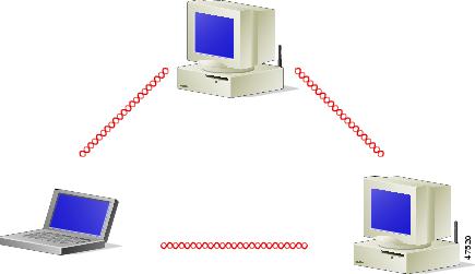
An ad hoc (or peer-to-peer) wireless LAN (see Figure 1-2) is the simplest wireless LAN configuration. In a wireless LAN using an ad hoc network configuration, all devices equipped with a client adapter can be linked together and communicate directly with each other. The use of an infrastructure device, such as an access point, is not required.
Figure 1-2 Ad Hoc Wireless LAN
Wireless Infrastructure with Workstations Accessing a Wired LAN
A microcellular network can be created by placing two or more access points on a LAN. Figure 1-3 shows a microcellular network with workstations accessing a wired LAN through several access points.
This configuration is useful with portable or mobile stations because it allows them to be directly connected to the wired network even while moving from one microcell domain to another. This process is transparent, and the connection to the file server or host is maintained without disruption. The mobile station stays connected to an access point as long as it can. However, once the transfer of data packets needs to be retried or beacons are missed, the station automatically searches for and associates to another access point. This process is referred to as seamless roaming.
Figure 1-3 Wireless Infrastructure with Workstations Accessing a Wired LAN

 Feedback