ITDについて
Intelligent Traffic Director(ITD)は、レイヤ 3 およびレイヤ 4 のトラフィック分散、ロードバランシング、およびリダイレクトのためのスケーラブルなアーキテクチャを構築できる、インテリジェントなハードウェア ベースのマルチテラビット ソリューションです。
ITD のメリット:
-
ライン レートでのマルチテラビット ソリューション
-
エンドデバイスへの透過性とステートレス プロトコルのメリット
-
Web Cache Communication Protocol(WCCP)やポリシーベースのルーティングなどの代替機能のための複雑さとアーキテクチャのスケーリングの軽減
-
プロビジョニングが簡素化され導入が容易
-
レガシー サービス アプライアンスは新しいものと共存できます
-
高価な外部ロードバランサの要件を削除します。
-
デバイスと Cisco NX-OS スイッチ間の認証/統合/認定が不要。
-
大幅な OPEX 削減の順序:構成の簡素化、展開の容易さ
-
サービス モジュールまたは外部 L4 ロードバランサは不要すべての Nexus ポートをロードバランサとして使用可能
ITD の機能:
-
ワイヤスピードでのハードウェアベースのマルチテラビット/秒 L3/L4 ロードバランシング
-
ゼロ遅延のロードバランシング
-
ラインレート トラフィックを任意のデバイスにリダイレクト、たとえば web cache エンジン、Web アクセラレータ エンジン(WAE)、ビデオキャッシュ、など)
-
ファイアウォール、侵入防御システム(IPS)、または Web アプリケーション ファイアウォール(WAF)、Hadoop クラスタなどのデバイスのクラスタを作成する機能
-
IP スティッキネス
-
ワイヤスピードでのハードウェアベースのマルチテラビット/秒 L3/L4 ロードバランシング
-
ゼロ遅延のロードバランシング
-
ラインレート トラフィックを任意のデバイスにリダイレクト、たとえば web cache エンジン、Web アクセラレータ エンジン(WAE)、ビデオキャッシュ、など)
-
ファイアウォール、侵入防御システム(IPS)、または Web アプリケーション ファイアウォール(WAF)、Hadoop クラスタなどのデバイスのクラスタを作成する機能
-
IP スティッキネス
-
回復力(回復力のある ECMP など)、一貫したハッシュ
-
仮想 IP ベースの L4 ロードバランシング
-
ノード間で加重負荷分散と Failaction がサポートされています
-
多数のデバイス/サーバーへの負荷分散
-
リダイレクトおよびロードバランシングと同時の ACL
-
双方向のフロー一貫性。A–>B および B–>A からのトラフィックは同じノードに行きます
-
サーバ/アプライアンスを Nexus スイッチに直接接続する必要なし
-
IP SLA ベースのプローブを使用したサーバー/アプライアンスのヘルスの監視
-
N + M 冗長(N ノード数、M ホットスタンバイ数)
-
サーバー/アプライアンスの自動障害処理
-
VRF サポート、vPC サポート
-
IPv4 と IPv6 の両方をサポート(すべてのプラットフォームは IPv6 をサポートしていません)
-
ITD 機能によるスーパーバイザ CPU への負荷の追加なし
-
無制限のフロー数を処理。
-
無停止でのノードの追加または削除
-
同時リダイレクトと負荷分散
-
同じスイッチ内の複数の ITD サービス間でのレート共有
使用例:
-
ファイアウォールのクラスタへの負荷分散。
-
NX-OS デバイスへのロード バランシングにより、IPS、IDS、および WAF を拡張します。
-
低コストの VM/コンテナ ベースの NFV にロードバランシングすることにより、NFV ソリューションを拡張します。
-
WAAS/WAE ソリューションをスケーリングします。Wide Area Application Services(WAAS)または Web Accelerator Engine(WAE)ソリューションのトラフィック リダイレクト メカニズム
-
VDS-TC(ビデオ キャッシュ)ソリューションのスケーリング
-
トラフィックを L7 LB に分散することにより、レイヤ 7 ロードバランサーをスケーリングします。
-
ECMP またはポートチャネルを置き換えて、再ハッシュを回避します。ITD は復元力があり、ノードの追加/削除/失敗時に再ハッシュを引き起こしません
-
DSR(Direct Server Return)モードでのサーバー負荷分散
-
NX-OS デバイスへのロード バランシングにより、NG 侵入防御システム(IPS)と Web アプリケーション ファイアウォール(WAF)を拡大します。
-
レイヤ 5 からレイヤ 7 のロードバランサへの負荷分散
展開モード
ワンアーム展開モード
ワンアーム展開モードでサーバーをスイッチに接続できます。このトポロジでは、サーバーはクライアント トラフィックまたはサーバー トラフィックの直接パスに存在しないため、既存のトポロジやネットワークを変更することなく、サーバーをネットワークに接続できます。

vPC でのワンアーム展開モード
ITD は、仮想ポート チャネル(vPC)に接続されたアプライアンス プールをサポートします。ITD サービスは各スイッチで実行されます。ITD は、フローがノードを通過する一貫したトラフィックを得られるように各スイッチをプログラムします。
 (注) |
VPC シナリオ(ITD NAT を使用しない)に failaction バケット配布を使用して、VPC 経由で到達可能なノードの障害時にピア間で一貫した動作を維持することをお勧めします。 |

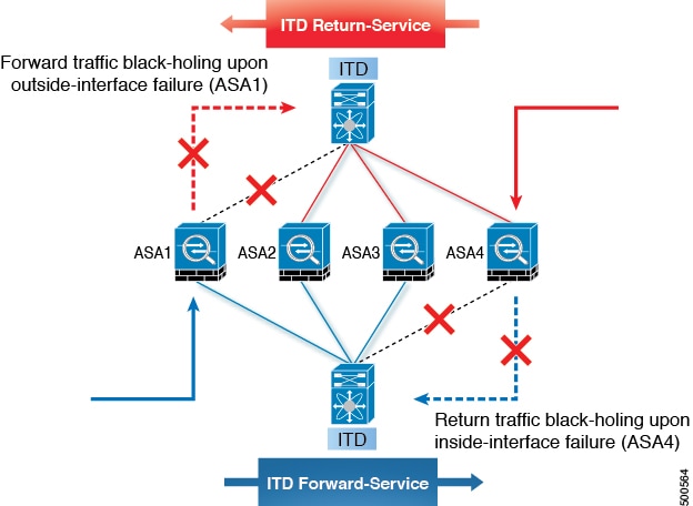
サンドイッチ展開モード
サンドイッチ展開モードでは、2 台のスイッチを使用してトラフィックをステートフルに処理します。
このモードの主な要件は、フローの転送トラフィックとリバース トラフィックの両方が同じアプライアンスを通過しなければならないことです。サンドイッチ展開の例としては、クライアントとサーバ間のトラフィックが同じアプライアンスを通過する必要があるファイアウォールおよびロード バランサの展開があります。
主な機能は次のとおりです。
-
ネットワーク セグメントごとの ITD サービス(外部ネットワーク用に 1 つの ITD サービスおよび内部ネットワーク用にもう 1 つの ITD サービス)。
-
入力方向の外部に接続するインターフェイス上で ITD サービスが動作するソース IP アドレス ロードバランシング スキーム。
-
入力方向のサーバーに接続するインターフェイスで ITD サービスが動作する宛先 IP アドレスのロード バランシング スキーム。
-
ユーザー定義のアクセス リスト(ACL を含む)が外部ネットワークの ITD サービスで使用されている場合、逆の ACE ルールを持つアクセス リストを作成し、内部ネットワークの ITD サービスのユーザー ACL として適用する必要があります。

サーバー ロードバランシング展開モード
ITD サービスは、スイッチで仮想 IP(VIP)をホストするように構成できます。VIP を宛先とするインターネット トラフィックの負荷は、複数のアクティブなノードに分散されます。ITD サービスはステートフル ロードバランサではありません。
(注) |
各スイッチで同様の方法で、ITD サービスを手動で設定する必要があります。 |

宛先 NAT
ネットワーク アドレス変換(NAT)は、ロードバランシング、ファイアウォール、およびサービス アプライアンスで一般的に導入されている機能です。接続先 NAT は、ロードバランシングで使用される NAT のタイプの 1 つです。
接続先 NAT のメリット
ITD 展開で NAT を使用するメリットは次のとおりです。
-
DSR(Direct Server Return)モードの展開のように、サーバー プール内のすべてのサーバーが仮想 IP アドレスをホストする必要はありません。
-
サーバー IP を認識する必要がないクライアントは、常にトラフィックを仮想 IP アドレスに送信します。
-
ロードバランサはサーバーの障害を検出し、クライアントがプライマリサーバーのステータスを認識しなくても、トラフィックを適切なサーバーにリダイレクトします。
-
NAT は、クライアントから実サーバーの IP を隠すことでセキュリティを提供します。
-
NAT により、異なるサーバープール間で実サーバーを移動する際の柔軟性が向上します。
さまざまなタイプの NAT の中で、接続先 NAT は、次のメリットがあるため、負荷分散で一般的に展開されます。
-
送信元またはクライアントから仮想 IP アドレスへのトラフィックは書き換えられ、サーバーにリダイレクトされます。
-
送信先またはクライアントから宛先またはサーバーへのトラフィック(転送パス)は、次のように処理されます。送信先またはクライアントから仮想 IP アドレスへのトラフィックは、ソースから接続先またはサーバーへのトラフィックとして変換およびリダイレクトされます。
-
接続先から送信元またはクライアントへのトラフィック(リバース パス)は、仮想 IP アドレスを送信元 IP アドレスとして再変換されます。
次の図は、仮想 IP アドレスを使用した NAT を示しています。

ポート アドレス変換(PAT)
PAT では、実際のアドレスおよび送信元ポートが 1 つのマッピング アドレスおよび固有のポートに変換されることによって、複数の実際のアドレスが 1 つのマッピング IP アドレスに変換されます。使用できる場合、実際の送信元ポート番号がマッピング ポートに使用されます。ただし、実際のポートが使用できない場合は、デフォルトで、マッピング ポートは実際のポート番号と同じポート範囲(0 ~ 511、512 ~ 1023、および 1024 ~ 65535)から選択されます。PAT では単一のマッピング先のアドレスを使用するため、ルーティング可能なアドレスの使用を抑えることができます。
VXLAN 上の ITD
単一のスイッチ ソリューションであった ITD は、VxLAN ファブリックのロードバランサーとして機能するようになりました。
プログラム可能なファブリックでは、サーバー、仮想マシン(VM)、およびコンテナー(特定のサービスに固有)をファブリック全体に分散させ、さまざまな ToR またはリーフスイッチに接続できます。ITD Over VXLAN 機能により、ファブリック全体に分散されたサーバーへのロードバランシングが可能になります。
ITD Over VXLAN により、ファブリックは大規模なロードバランサーとして機能し、大規模なテレメトリと分析を提供できるようになります。ITD Over VXLAN をロードバランサとして使用すると、ファブリック内の任意の場所にあるレイヤ 4 アプライアンスとレイヤ 7 アプライアンス間を接続できます。これは、図 「ファブリック全体のロードバランシング」に示されています。

データベース サーバー、アプリケーションサーバー、Web サーバー、ファイアウォール、WAAS、IPS、IDS、およびビデオ キャッシュを含む多数のクライアント(ローカルおよびボーダーリーフを越えて)がある場合があります。トラフィックの高低に関する情報を含む、ファブリック内の各デバイスから各ファイアウォール、WAAS、IPS、IDS、およびサーバーに流れるトラフィックに関する情報は非常に貴重です。
ITD Over VXLAN は、クライアントとサーバーまたはレイヤ 4 およびレイヤ 7 サービス間のパス上にあり、トラフィック情報を認識します。この情報を使用して、貴重なトラフィック分析とテレメトリを提供します。
ロードバランシング機能では、仮想 IP(VIP)が、DC ファブリック全体に分散された物理サーバーファームによって提供されるサービスを抽象化します。さまざまなクライアント(ローカルからファブリックへ、またはリモート ロケーションから)が特定のサービスの要求を送信すると、これらの要求は常にこれらのサーバーの VIP に送信されます。
ToR またはリーフスイッチでは、ITD は送信元 IP アドレスのビットとマスク、宛先 IP アドレス(仮想 IP アドレス)、および関連するレイヤ 3 またはレイヤ 4 フィールドを照合して、これらの要求をサーバー間で負荷分散します。
ITD Over VXLAN は、デバイス グループ内のサーバー(ノード)のクラスタを構成するためのインフラストラクチャを提供します。バケット(ビット マスク)に基づいてクライアント トラフィックと ITD サービスで構成されたテナント SVI を分離します。ノード(サーバー)とバケットの定義済みクラスタに基づいて、ITD は、クライアント IP トラフィックをバケット マスクに一致させるルールを自動的に作成し、一致したトラフィックを特定のサーバー ノードにリダイレクトします。
サーバーが応答しなくなった場合や動作不能になった場合、ITD はクライアント トラフィックを非動作ノードから単一または構成済みのスタンバイ ノードのグループに自動的に切り替えます。トラフィックの割り当ては、フローをスタンバイ ノードに自動的に変更することによって実現されます。
ITD Over VXLAN は現在、Direct Server Return(DSR)の概念と機能を使用しているため、サーバーの応答がクライアントに直接送信されます。これはファブリックに依存しませんが、現在 VXLAN EVPN ファブリックでサポートされており、VXLAN 経由の PBR をサポートする Cisco Nexus 9000 シリーズ スイッチで現在サポートされています。
ITD Over VXLAN は、ライン レートの速度で実現されます。

VXLAN トポロジを介した ITD の設定の概要
ToR スイッチでの VXLAN 経由の ITD 設定の概要は次のとおりです。
-
負荷分散サーバーを特定し、デバイス グループを作成します。
-
グループの ITD サービス インスタンスを作成し、以下を完了します。
-
着信する ITD Over VXLAN トラフィックに仮想 IP アドレス(VIP)を関連付けます。VIP は、デバイス グループ内のサーバーを表します。
-
他の負荷分散構成を有効にします。
-
サービスをアクティブにする必要があるインターフェイスを、サービスの入力インターフェイスとして構成します。ITD サービスをイネーブルにします。
-
サーバー(ITD ノード)が接続されているすべてのリーフスイッチに同一の ITD 設定を適用します。これらのリーフスイッチで、このサービスの入力インターフェイスとして L3 VNI を設定します。ITD サービスをイネーブルにします。
-

VXLAN 上での ITD のメリット
-
ファブリック内の任意の場所に分散されたサーバー/VM/コンテナの負荷分散
-
ハードウェアに依存しない
-
直接接続されたノードのデータプレーン内のノードのヘルスモニタリングとプローブの要約。
-
分析とテレメトリは、サーバー(つまり、VM/コンテナの生成)およびアプライアンス(エラスティック データセンター)の容量をいつ/どのように拡大するかについての詳細を提供します。
-
エラスティック データセンターを構築します。
-
VXLAN ネットワーク識別子(VNI)インターフェイス間の負荷分散。
-
ファブリック内の複数のスイッチ間でのロードバランシングの同期。
-
障害情報の自動同期。
-
推奨システム
-
可能なすべてのデータセンター トポロジーを備えた VXLAN-EVPN ファブリックで動作します。
レイヤ 2 ロードバランシングについて
レイヤ 2(ITD-L2)ロードバランシングは、Cisco Nexus スイッチでのレイヤ 2 トラフィック分散、ロードバランシング、およびリダイレクトのためのハードウェア ベースのマルチテラビット ソリューションです。
(注) |
ITD-L2 機能は、Cisco 9500 EX/FX ラインカードではサポートされていません。 |
ITD-L2 は、単一の論理リンクを作成する複数の物理リンクの集合体です。複数の物理リンクをポート グループにバンドルして、帯域幅(複数の物理リンクの集合体)と冗長性を向上させることができます。
レイヤ 2 内の 1 つのポートに障害が発生すると、トラフィックはレイヤ 2 の残りのポートに切り替わります。
ITD-L2 を使用すると、透過モード アプライアンスのクラスタを作成できます。
レイヤ 2 ロード バランシング機能
ITD-L2 の機能は次のとおりです。
-
ライン レートでのマルチテラビット ソリューション
-
プロビジョニングが簡素化され導入が容易
-
エンドデバイスへの透過性とステートレス プロトコルのメリット
-
高価な外部ロードバランサの要件を削除します。
ITD レイヤ 2 ロードバランシングのメリット
ITD レイヤ 2 ロードバランシングのメリットは次のとおりです。
-
同時リダイレクトおよびロードバランシング
-
IP スティッキ性および復元力
-
ポートのヘルス モニタリング
-
高価な外部ロードバランサの要件を削除します。
-
ハッシングは、配線やポートの番号付けに依存しません
-
スイッチのすべてのポートは、負荷分散とトラフィックのリダイレクトに使用されます
展開使用例
ITD-L2 機能の展開使用の例は次のとおりです。
-
ファイアウォールのプールへの負荷分散。
-
VDS-TC(ビデオ キャッシュ)ソリューションをスケーリングします。
-
トランスペアレント モードのデバイスをスケーリングします。
ITD-L2 のトポロジの例
このセクションには、次の例が表示されます。
-
ITD-L2 の基本トポロジ
-
ITD-L2 構成の使用例
-
回復力のあるハッシュの失敗アクション


レイヤ 2 ロードバランシングの前提条件
レイヤ 2 ロードバランシングには、次の前提条件があります。
-
十分な TCAM サイズが VACL に割り当てられていることを確認する必要があります。TCAM サイズを確認するには、 sh hardware access-list tcam region コマンドを使用します。適切な TCAM サイズが割り当てられていない場合は、 hardware access-list tcam region VACL <256 の倍数のサイズ > コマンドを使用して、適切な TCAM サイズを割り当てます。
デバイス グループ(Device Groups)
ノードは、トラフィックを負荷分散できる物理サーバー、仮想サーバー、またはサービス アプライアンスにすることができます。これらのノードはデバイス グループの下にグループ化され、このデバイス グループをサービスにマップできます。
ITD はデバイス グループをサポートします。デバイス グループを構成するときは、次を指定できます。
-
デバイス グループのノード
-
デバイス グループのプローブ
プローブは、デバイス グループ レベルまたはノード レベルで構成できます。ノード レベルのプローブを行う場合、それぞれのノードは自身のプローブで構成可能なため、ノードごとにさらにカスタマイズすることができます。ノード レベルのプローブは、障害状態について各ノードを別々に監視する必要があるシナリオで役立ちます。
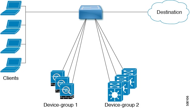
ITD サービス内の複数のデバイス グループ
デバイス グループがサポートされています(下図を参照してください)。ITD サービスは、さまざまなデバイス グループを指すさまざまなシーケンスを持つ単一のルートマップを生成します。
各デバイス グループは、異なるサービスを必要としますが、同じ入力インターフェイスに到着する異なるタイプのトラフィックを表します。インターフェイス上のトラフィックは、仮想 IP アドレスに基づいて適切なデバイス グループにリダイレクトされます。同じインターフェイスで ITD サービスごとに複数のデバイス グループをサポートすると、ITD を拡張できます。
ITD サービスで複数のデバイス グループを設定する方法を示す構成例については、 を参照してください。
VRF のサポート
ITD サービスは、デフォルト VRF でもデフォルト以外の VRF でも構成できます。
ITD サービスでトラフィックをリダイレクトするには、入力インターフェイスおよびデバイス グループ ノードのすべてが同じ VRF に属している必要があります。設定済み VRF で、関連するデバイス グループのすべての入力インターフェイスおよびノード メンバーが到達可能であることを確認する必要があります。
ルータ ACL
スイッチは、ITD を使用したルータ アクセス コントロール リスト(RACL)をサポートします。
同じ入力インターフェイスで ITD と RACL を構成できます。TCAM にダウンロードされる構成結果の RACL は、ITD によって生成された ACL とユーザ構成 RACL を合わせた成果物です。RACL で構成された permit ステートメントと deny ステートメントは、ITD によって作成された ACL 許可およびリダイレクト エントリと結合されます。この機能により、選択したトラフィックのフィルタリングおよび負荷分散を行うことができます。
(注) |
|
ACL の組み込みと除外
インクルード ACL
インクルード ACL 機能を使用すると、ITD サービスにアクセス制御リスト(ACL)を割り当てることができます。ACE に一致するトラフィックのみがノードに向かって負荷分散され、他のトラフィックはデフォルトのルーティング ルールに従います。
Cisco NX-OS リリース 9.3(3) 以降、1 つの ITD サービスで最大 8 つのアクセス リストを設定できます。各アクセス リストを独自のデバイス グループ(マルチ ACL)に関連付けることができます。特定のデバイス グループが 1 つのユーザー ACL に関連付けられている場合、そのデバイス グループが優先され、デフォルトのデバイス グループが上書きされます。この機能により、ITD はさまざまな ACL に一致するトラフィックをさまざまなデバイス グループにロードバランシングできます。
除外 ACL
除外 ACL を設定して、ITD が ITD ロードバランサから除外するトラフィックを指定できます。除外 ACL が選択するトラフィックは RIB ルーティングされ、ITD をバイパスします。除外 ACL は、送信元フィールドと接続先フィールドの両方に基づいてフィルタリングできます。除外 ACL は、仮想 IP アドレスの前にあります。
仮想 IP アドレスのフィルタリング
仮想 IP アドレスを使用して、ITD のトラフィックをフィルタリングできます。トラフィックフィルタリング用の仮想 IP アドレスとサブネット マスクの組み合わせは、宛先フィールドでのみサポートされます。
ポート番号ベースのフィルタリング
ポート番号付けを使用して、ITD のトラフィックをフィルタリングできます。レイヤ 4 ポート(たとえば、ポート 80)に基づいてトラフィックをフィルタリングするために、次の方法がサポートされています。
-
一致する宛先ポート
宛先ポートが 80 の任意の送信元または宛先 IP アドレスが一致します。(例:仮想 IP アドレスは 0.0.0.0 0.0.0.0 tcp 80 として構成されています。)
-
一致する送信元ポート
80 以外のポートは ITD をバイパスし、ポート 80 はリダイレクトされます。(例:除外 ACL は、permit tcp any neq 80 any として設定されます。)
-
複数のポート番号の一致
ITD では、ポートごとに 1 つずつ、複数の仮想 IP アドレス行を設定できます。
ホットスタンバイ
ホットスタンバイ機能は、スイッチを再構成して、動作可能なホットスタンバイ ノードを探し、最初に使用可能なホットスタンバイ ノードを選択して、障害が発生したノードを置き換えます。ITD は、障害が発生したノードを当初宛先としていたトラフィック セグメントを、ホットスタンバイ ノードにリダイレクトするようにスイッチを再設定します。このサービスは、ホットスタンバイ ノードとアクティブ ノードとの固定マッピングを強要しません。
障害が発生したノードが再び動作可能になると、アクティブ ノードとして復元されます。動作中のホットスタンバイ ノードからのトラフィックは元のノードにリダイレクトされ、ホットスタンバイ ノードはスタンバイ ノードのプールに戻ります。
複数のノードで障害が発生した場合、それらすべてのノードを宛先とするトラフィックは、最初に使用可能なホットスタンバイ ノードにリダイレクトされます。
ホットスタンバイ ノードは、ノード レベルでのみ構成できます。ノード レベルで、関連付けられたアクティブ ノードが失敗した場合にのみホットスタンバイ ノードはトラフィックを受信します。
ITD は N + M 冗長性をサポートしており、M ノードは N アクティブ ノードのホットスタンバイ ノードとして機能できます。
複数の入力インターフェイス
複数の入力インターフェイスに対してトラフィック リダイレクト ポリシーを適用するように ITD サービスを構成できます。この機能では、単一の ITD サービスを使用して、さまざまなインターフェイスに到着するトラフィックを一連のノードにリダイレクトできます。
Cisco NX-OS リリース 7.0(3)I7(3) 以降、同じ入力インターフェイスを 2 つの ITD サービスに含めることができ、1 つの IPv4 ITD サービスと 1 つの IPv6 ITD サービスが可能になります。
IPv4 と IPv6 の両方の ITD サービスに同じ入力インターフェイスを含めると、IPv4 と IPv6 の両方のトラフィックが同じ入力インターフェイスに到着することができます。IPv4 トラフィックをリダイレクトするために IPv4 ITD ポリシーが適用され、IPv6 トラフィックをリダイレクトするために IPv6 ITD ポリシーが適用されます。
(注) |
同じ入力インターフェイスが複数の IPv4 ITD サービスまたは複数の IPv6 ITD サービスで参照されていないことを確認してください。システムはそれを自動的に適用せず、サポートされていません。 |
システム ヘルスモニタリング
ITD は、ノードとそれらのノードで実行されているアプリケーションの状態を定期的に監視して、障害を検出し、障害シナリオを処理します。
ICMP、TCP、UDP、DNS、および HTTP プローブがサポートされています。
ノードに接続されたインターフェイスの正常性
Cisco NX-OS リリース 7.0(3)I3(1) 以降、ITD ITD は IP サービスレベル アグリーメント(IP SLA)機能を利用して、各ノードを定期的にプローブします。以前のリリースでは、ITD は Internet Control Message Protocol(ICMP)を使用して、各ノードを定期的にプローブします。プローブはデフォルトで 10 秒の頻度で送信され、1 秒まで設定できます。それらはすべてのノードに同時に送信されます。プール グループ構成の一部としてプローブを構成できます。
プローブは、デフォルトで 3 回再試行した後に障害が発生したと宣言されます。この時点で、ノードの状態は「機能不全」、ステータスは「PROBE_FAILED」になります。
ノード障害の処理
ノードがダウン状態としてマークされると、ITD はトラフィックの中断を最小限に抑えて、トラフィックを残りの運用可能なノードに再配布するために自動的に次のタスクを行います。
-
障害が発生したノードを引き継ぐようにスタンバイ ノードが構成されているかどうかを判別します。
-
スタンバイ ノードが運用可能な場合、トラフィックを処理するノードの候補としてそのノードを識別します。
-
運用可能なスタンバイ ノードを使用できる場合、トラフィックを処理するアクティブ ノードとしてそのスタンバイ ノードを再定義します。
-
障害が発生したノードから新しくアクティブにされたスタンバイ ノードにトラフィックを再割り当てするように自動的にプログラムします。
プローブのユーザー定義トラック ID
ユーザーは独自のトラックを定義し、それらを各ノードに関連付けることができます。ノードにユーザー定義のトラックが割り当てられている場合、対応する ip sla 構成は、トラックを操作するユーザーによって構成される必要があります。ITD は、ノードに新しいトラックと ip sla ID を割り当てません。ユーザー定義のトラックは、プライマリ、スタンバイ、およびホット スタンバイ ノードに割り当てることができます。ユーザーは、ITD セッションによって追加された新しいノードにユーザー定義のトラックを割り当てることができます。ITD によって生成されたトラックは、ユーザー定義のトラックとして使用できません。
ユーザー定義のトラックを使用して新しいノードを追加する例:
itd device-group dg1
  node ip 1.1.1.2
    probe track 30
  node ip 1.1.1.3
    probe track 40
  node ip 1.1.1.4
    mode hot-standby
    probe track 50

itd device-group dg2
  node ip 1.1.1.6
    probe track 70
    standby ip 1.1.1.5
      probe track 60
ノードにユーザー定義のトラックがない場合、サービスが有効になったときに、ITD サービスは track id および ip sla ID を割り当てます。
ピア同期
ピア同期機能は、サンドイッチ モードで 2 つの ITD ピア サービス間でノードのヘルス ステータスを同期します。いずれかの ITD ピア サービスのリンクがダウンした場合のトラフィック損失を防ぐのに役立ちます。
各 ITD サービスは、ピア サービスを定期的にプローブして、障害を検出します。ping は毎秒 ITD ピア サービスに送信されます。応答が受信されない場合は、3 回再試行されます。頻度と再試行回数は構成できません。
(注) |
ピア サービス機能では、サービス間でノードの同期フェールオーバーを可能にするために、fail-action 最小バケットまたはバケットごとの fail-action ノードを構成する必要があります。さらに、いずれかのサービスがホット スタンバイ ノードまたはノード レベルのスタンバイを使用している場合、同期フェールオーバーはサポートされません。 |
Failaction 再割り当て
ITD の Failaction により、障害が発生したノードへのトラフィックを 1 つ以上の現用系ノードに再割り当てできます。障害が発生したノードが再び現用系になると、接続の処理が再開されます。すべてのノードがダウンした場合、パケットは自動的にルーティングされます。すべての Failaction メカニズムは、IPv4 サービスと IPv6 サービスの両方でサポートされます。
(注) |
Failaction 機能をイネーブルにする前に、ITD デバイス グループにプローブを設定する必要があります。 |
Failaction ノードの再割り当て
ノードがダウンすると、そのノードに関連付けられたトラフィック バケットは、構成されている一連のノードで最初に検出されたアクティブ ノードに再割り当てされます。新しく再割り当てされたノードでも障害が発生すると、トラフィックは次に使用可能なアクティブ ノードに再割り当てされます。
ノードが回復し、それ以上の障害イベントがない場合は、障害が発生する前にノードに最初に割り当てられていたトラフィック バケットがそのノードに再割り当てされます。
Failaction ノードの最小バケット(Failaction Node Least-Bucket)
ノードがダウンすると、そのノードに関連付けられたトラフィック バケットは、現在最小数のトラフィック バケットからトラフィックを受信している現用系ノードに再割り当てされます。後続のノード障害ごとに、トラフィック バケットが最も少ない現用系ノードが再計算され、障害が発生したノードに向けられたすべてのバケットがこのノードにリダイレクトされるため、再割り当てされたバケットを複数の現用系ノードに分散できます。
ノードが回復し、それ以上の障害イベントがない場合は、障害が発生する前にノードに最初に割り当てられていたトラフィック バケットがそのノードに再割り当てされます。
Failaction バケット分配(Failaction Bucket Distribute)
サービスが有効な場合、ITD は内部アルゴリズムを使用して、プライマリ ノードのさまざまなシーケンスを、プライマリ ノードごとに異なる優先順位を持つ代替バックアップ パスとして事前に選択します。ノードがダウンすると、そのノードへのトラフィックは、優先度が最も高い最初の現用系バックアップ ノードにリダイレクトされ、その後の障害についても同様にリダイレクトされ、それによってコンバージェンスの遅延が最小限に抑えられます。
ノードが回復すると、最初にプライマリとしてこのノードに割り当てられていたトラフィック バケットがそのノードに再割り当てされます。プライマリ ノードがまだ障害状態であり、新しく回復したノードが最も優先順位の高い現用系バックアップとして動作するトラフィック バケットも、そのトラフィック バケットに再割り当てされます。
のプライマリ ノード、またはデバイス グループの最大 32 のプライマリ ノード(いずれか少ない方)が、ノードごとに異なる優先順位で事前に選択されます。
(注) |
このアルゴリズムは、比較的均等なトラフィック分散を目的としていますが、ノード障害が発生した場合の均等な分散を保証するものではありません。 |
Failaction 最適化
Cisco NX-OS リリース 9.2(2) より前では、ノードがダウンすると、そのノードに関連付けられたバケットは、fail-action アルゴリズムの決定に従ってアクティブ ノードに再割り当てされます。ただし、新しく再割り当てされたノードにも同時に障害が発生した場合、障害アクションの計算を再実行した後、元の障害ノードのトラフィック バケットを別のアクティブ ノードに再割り当てする必要があります。障害が発生したノード バケットをアクティブ ノードに再割り当てする際の遅延は、ネットワーク パフォーマンスに影響します。
fail-action の最適化では、ノードがダウンすると、利用可能なすべてのノードのステータスが最初に事前に取得されます。障害として検出されたすべてのノードの再割り当ては、失敗アクション メカニズムに基づいて実行されるため、再割り当ての繰り返しによる遅延が回避されます。
Cisco NX-OS リリース 9.3(3) 以降、この最適化は、ピア同期が設定されている場合を除き、すべてのサービスに対してデフォルトで有効になっています。
Failaction Node-Per-Bucket
特定のノードに障害が発生すると、バケットの数が最も少ないノードが識別され、バケットは、バケットの数が最も少ないノードから開始して、他のアクティブ ノードに分散されます。
ITD は、現在最も少ないバケット ノードを繰り返し識別し、すべてのバケットが再割り当てされるまで、そのノードに 1 つのバケットを割り当てます。したがって、すべてのバケットは、残りのすべてのアクティブ ノード間で均等に分散されます。
(注) |
Cisco Nexus NX-OS リリース 9.3(5) 以降、ITD ITD は、ノードの重みに基づいて、フェールオーバーするノードを識別します。ノードに重みが設定されていない場合、デフォルトの重み 1 が使用されます。 |
Failaction 再割り当てを使用しない場合
Failaction によるノードの再割り当てを設定しない場合は、次の 2 つのシナリオが考えられます。
プローブを構成して Failaction 再割り当てをしない
ITD プローブでは、ノードの障害やサービス到達可能性の消失を検出できます。ノードに障害が発生した場合、failaction が設定されていないため、トラフィックはルーティングされ、再割り当てされません。ノードが回復すると、その回復したノードがトラフィックの処理を開始します。
プローブの構成なしで Failaction 再割り当てをしない
プローブが構成されていないと、ITD はノードの障害を検出できません。ノードがダウンしても、ITD はアクティブ ノードへのトラフィックの再割り当てまたはリダイレクトを行いません。


 フィードバック