Deploying Layer 4 to Layer 7 Services

Overview

The Cisco Cloud APIC enables you to deploy Layer 4 to Layer 7 service devices to the public cloud. The initial release (4.2(x)), supports Azure Application Gateway (Application Load Balancer) deployments in Azure. Beginning with release 5.0(2), Azure Load Balancer (Network Load Balancer) and Third Party Firewall deployments in Azure are supported. Beginning with release 5.1(2), Third Party Load Balancer deployments in Azure are supported.

Four types of Layer 4 to Layer 7 services are supported for deployments in Azure:

  • ALB refers to Azure Application gateway or Application Load balancer

  • NLB refers to Azure Load balancer or Network Load balancer

  • Third Party Firewall

  • Third Party Load Balancer

About Service Graphs

A service graph is used to represent a set of Layer 4 to Layer 7 services devices inserted between two or more pair of EPGs. EPGs can represent your applications running within a cloud (for example, Cloud EPG) or internet (cloudExtEPG) or from other sites (for example, on-premises or remote cloud sites). Layer 4 to Layer 7 services devices can be NLB, ALB, a cluster of third party firewalls or a third party load balancer.

A service graph in conjunction with contracts (and filters) is used to specify communication between two EPGs. A cloud APIC automatically derives security rules (network security group/NSG and ASG) and forwarding routes (UDRs) based on the policy specified in Contract and Service Graph

Multiple service graphs can be specified to represent different traffic flows or topologies.

Following combinations are possible with service graphs:

  • Same device can be used in multiple service graphs.

  • Same service graph can be used between multiple consumer and provider EPGs.

By using a service graph, the user can specify the policy once and deploy the service chain within regions or inter-regions. Each time the graph is deployed, Cisco ACI takes care of changing the network configuration to enable the forwarding in the new logical topology.

For Third party firewalls, the configuration inside the device is not managed by cloud APIC.

A service graph represents the network using the following elements:

  • Service Graph Nodes—A node represents a function that is applied to the traffic, such as a load balancer. A function within the service graph might require one or more parameters and have one or more connectors.

  • Connector—A connector enables input and output from a node.

After the graph is configured, the Cisco APIC automatically configures the services according to the service function requirements that are specified in the service graph. The Cisco APIC also automatically configures the network according to the needs of the service function that is specified in the service graph, which does not require any change in the service device.

Using Service Graphs with Cloud Native and Third-Party Services

Beginning with Release 5.1(2), you can now use service graphs with cloud native and third-party services. You can use service graphs in these situations either with or without redirect. See Example Use Cases for Service Graphs with Cloud Native and Third-Party Services for example use cases, with or without redirect.

You will use the cloud service endpoint group (service EPG), also introduced in Release 5.1(2), with this type of service graph. See Cloud Service Endpoint Groups for more information about the service EPG, and the deployment types and access types that are available for service EPGs.

The following deployment types and access types are supported with service graphs used with service EPGs for this purpose.

Table 1. Provider Service EPG Types

Deployment Types

Access Types

Cloud Native

Private

Cloud Native Managed

Public and Private

Third-Party

Private

Table 2. Consumer Service EPG Types

Deployment Types

Access Types

Cloud Native Managed

Public and Private

Guidelines and Limitations
  • You must have the newer NSG-per-subnet configuration enabled in order to use service graphs with cloud native and third-party services, using the service EPGs. See Security Groups for more information on the NSG-per-subnet configuration.

  • Any restrictions that apply for cloud EPG and service graph combinations also apply to service EPG and service graph combinations. For example, the cloud EPG/service graph restriction that a consumer and provider that is tag-based cannot be in the same VRF in the same region would also apply for service EPGs and service graphs.

  • For two node graphs that don't perform redirect, SNAT and DNAT are enabled. It is assumed that the DNATed address is a device that is equivalent to a load balancer, which can take care of spraying traffic across different targets that may be in different subnets.

    Note that if those targets are in different subnets, the service graph doesn't provide route reachability rules for those targets. It is assumed that the service EPG will take care of the reachability in this case.

  • For cases involving AKS and service graphs, the service graph will only establish route reachability to the load balancer's subnet of the AKS cluster.

About Application Load Balancers

Application Load Balancer (also called Azure Application Gateway or ALB) is a Layer 7 load balancer, which balances the web traffic based on attributes like HTTP request, URL filtering etc. For more details please refer to Microsoft Documentation.

In Cisco ACI, there are two ways to deploy an Application Load Balancer:

  • Internet-facing: inserts the Application Load Balancer as a service between the consumer external EPG and the provider cloud EPG.

  • Internal-facing: inserts the Application Load Balancer as a service between the consumer cloud EPG and the provider cloud EPG.

You can consume an Application Load Balancer using a service graph. A typical configuration involves:

  • Creation of Layer 4 to Layer 7 services device as Application Load Balancer

  • Consume the ALB as a node in the service graph

  • Creation of one or more listeners in EPG communication when a service graph is associated with a contract.

Listeners enable you to specify the ports and protocols (HTTP or HTTPS) that the Application Load Balancer accepts traffic on. When specifying HTTPS, you also choose a security policy and an SSL certificate.


Note

A listener can have multiple certificates.


All listeners require you to configure at least one rule (a default rule, which does not have a condition). Rules enable you to specify the action that the load balancer takes when a condition is met. For example, you can create a rule that redirects traffic to a specified URL when a request is made to a specified hostname or path.

An Application load balancer (ALB) should be in a separate subnet which should not be used to deploy other applications. Cloud APIC creates and attaches ALB’s NSG to the subnet associated with the ALB. Cloud APIC supports Standard and Standard_v2 SKUs of Azure Application Gateway.

About Network Load Balancer

A Network Load Balancer (Azure Load Balancer or NLB) is a Layer 4 device that distributes the in-bound flow packets based on Layer 4 ports. For more details, please refer to Microsoft Documentation.

Similar to ALB, NLB can be deployed using a service graph. You can specify these actions by configuring one or more listeners.

Listeners enable you to specify the ports and protocols (TCP or UDP) that the load balancer accepts and forwards traffic on. All listeners require you to configure at least one rule (a default rule, which does not have a condition). Rules enable you to specify the action that the load balancer takes when a condition is met. Unlike application gateway, here a rule can only forward traffic to specific port of the backend pool. NLB should be in a separate subnet similar to ALB. There are two modes of operation in Network load balancer:

  • Forward mode: Traffic is forwarded from a specific listener port to the specified backend port.

  • HA Port mode: Network load balancer will load balance TCP and UDP flows on all the ports simultaneously.

Cloud APIC supports Standard SKU Network Load Balancer only.

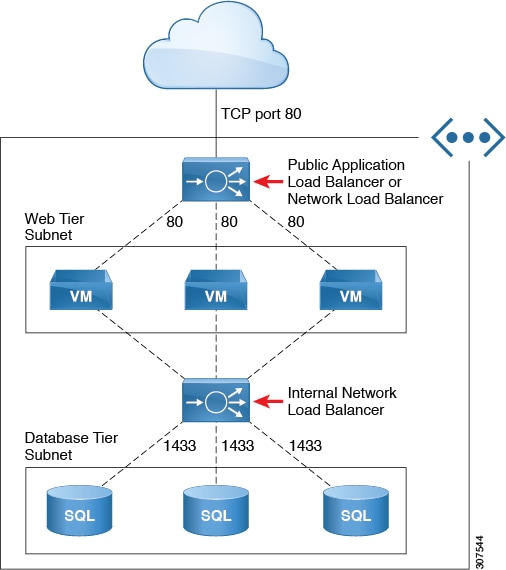
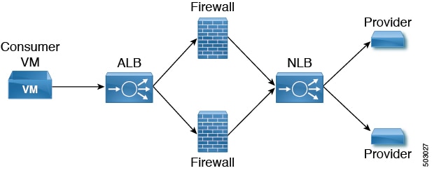
In Figure1, the frontend load balancer (ALB/NLB) - VM or firewall - backend load (ALB/NLB) balancer as a service are inserted between the consumer external EPG and the provider cloud EPG.

Figure 1. Internet-Facing and Internal-Facing Deployment

About Third-Party Load Balancers

Third-Party Load Balancer is a noncloud native Layer 4 to Layer 7 load balancer. Cloud APIC does not manage the configuration of the third-party load balancers. However, Cloud APIC automates the network stitching for connectivity to a third-party load balancer.

You can configure VIPs for a third-party load balancer from the external interface subnet. You can also configure additional VIPs for the third- party load balancers as secondary IP addresses on the external interface.

Cloud APIC supports third-party load balancers that are deployed in a two-arm mode (external and internal interfaces) with source NAT enabled.

Limitations for Third-Party Load Balancers:

  • Cloud APIC does not support Direct Server Return (DSR) configurations on third-party load balancers.

  • Third-party load balancers are not supported in active/standby high availability configurations.

    For details about third-party load balancer VMs in active/active mode, see Example Use Cases.

  • Alien VIP range is not supported for third-party load balancers.

About Allow All Traffic Option

Beginning with release 5.1(2g), the Allow All Traffic option is available for third-party firewalls and Azure network load balancers deployed as pass-through devices on a redirect-enabled service graph.


Note

This option allows all inbound and outbound access to the subnet on which the interface belongs. Ensure that this does not present a security risk before enabling this option.


The following sections provide instructions for enabling the Allow All Traffic option.

Third-Party Firewall

  • To enable this option when creating a new service graph type:

    1. From the Application Management list in the Intent menu, click Services > Devices > Create Device.

    2. Choose Third party firewall as the Service Type.

    3. Click Add Interface, then locate the Allow All Traffic area.

    4. Click the box next to the Enabled field in the Allow All Traffic area to allow all inbound and outbound access to the subnet on which the interface belongs.

    5. Click Save when finished.

  • To enable this option when editing an existing service graph type:

    1. From the Application Management list in the Intent menu, click Services, then click on an existing service device with Third-Party Firewall shown as the Device Type.

      A panel showing details for this service device type slides in from the right side of the window.

    2. Click the Details icon ().

      Another window appears that provides more detailed information for this service device type.

    3. Locate the Interfaces area in the window and click the necessary interface selector under the Interface Selectors column.

      A panel showing details for this interface slides in from the right side of the window.

    4. Click the Details icon ().

      Another window appears that provides more detailed information for this interface.

    5. Click the pencil icon to edit the configuration settings for this interface.

    6. Locate the Allow All Traffic area, then click the box next to the Enabled field in the Allow All Traffic area to allow all inbound and outbound access to the subnet on which the interface belongs.

    7. Click Save when finished.

Azure Network Load Balancer

  • To enable this option when creating a new service graph type:

    1. From the Application Management list in the Intent menu, click Services > Devices > Create Device.

    2. Choose Network Load Balancer as the Service Type.

    3. In the Settings area, click the box next to the Enabled field in the Allow All Traffic area to allow all inbound and outbound access to the subnet on which the interface belongs.

    4. Click Save when finished.

  • To enable this option when editing an existing service graph type:

    1. From the Application Management list in the Intent menu, click Services, then click on an existing service device with Network Load Balancer shown as the Device Type.

      A panel showing details for this service device type slides in from the right side of the window.

    2. Click the Details icon ().

      Another window appears that provides more detailed information for this service device type.

    3. Click the pencil icon to edit the configuration settings for this service device.

    4. In the Settings area, locate the Allow All Traffic area, then click the box next to the Enabled field in the Allow All Traffic area to allow all inbound and outbound access to the subnet on which the interface belongs.

    5. Click Save when finished.

Dynamic Server Attachment to Server Pool

Servers in provider EPG are dynamically added to the target groups. In Azure, the target groups are referenced as the backend pool. Listeners and rule configuration that define the frontend and backend protocol and port number, and load balancing action are provided by the user. When configuring listener rule as part of service graph configuration, user can select provider EPG for a given rule. The endpoints from that EPG would be dynamically added to the target group of the load balancer. You do not need to specify the endpoints or FQDN for the targets.

About Inter-VNet Services

Beginning with Release 5.0(2), support is available for the deployment and automation of the inter-VNet services. This is both for the East-West and North-South use cases within the cloud.

Note the following considerations for this support:

  • VNet peering needs to be configured for hub-spoke topology. For more information, refer to Configuring VNet Peering for Cloud APIC for Azure.

    • For multi-node services with redirect: The service device has to be present in the infra VNet. Service devices such as ALB fronting the provider can be present in the provider VNet.

    • For multi-node service without redirect: The service device can be in the provider VNet or spread across the hub VNet and the provider VNet.

  • Inter-VNet traffic is supported with an Application load balancer or Network load balancer in the infra VNet and the provider in a non-infra VNet. The VNets should be peered together and the load balancer and the provider should be from the same region.

About Multinodes

Beginning with release 5.0(2), Multinode service graph is supported. Multinodes enable multiple deployment scenarios with service graphs.

Service devices that can be deployed are Application Load Balancer, Network Load Balancer and Third Party Firewall.

Two types of nodes are admitted in a graph.

  • Non-redirect: Traffic is destined to service devices (Load Balancers, Thirdparty firewalls with DNAT and SNAT, Network Load Balancer).

  • Redirect: Service device is a passthrough device (Network Load Balancer or Firewall).

About Layer 4 to Layer 7 Service Redirect

Beginning with Release 5.0(2), the Layer 4 to Layer 7 Service Redirect feature is available for Cisco Cloud APIC, similar to the policy-based redirect (PBR) feature available for Cisco APIC. The Layer 4 to Layer 7 Service Redirect feature is configured using the Redirect option in the Cisco Cloud APIC.


Note

Throughout this section, the term "consumer-to-provider" is sometimes used as a blanket term to describe traffic going from point A to point B, where a redirect service device might be inserted between those two points. However, this does not mean that only consumer-to-provider traffic is supported for redirect; traffic might also be from provider-to-consumer, such as in the use case described in Spoke to Spoke.


With redirect, policies are used to redirect traffic through specific service devices, where service devices can be deployed as a Network Load Balancer or a third-party firewall. This traffic isn't necessarily destined for the service device as part of the standard consumer-to-provider configuration; rather, you would configure the consumer-to-provider traffic as you normally would, and you would then configure service graphs to redirect that consumer-to-provider traffic to a specific service device.

Support for redirect for Cisco Cloud APIC is only available in conjunction with the VNet peering feature, taking advantage of the hub-and-spoke topology used in VNet peering. For more information on the VNet peering feature, see the Configuring VNet Peering for Cloud APIC for Azure document.

About the Overlay-1 and Overlay-2 VRFs

The overlay-1 and overlay-2 VRFs are automatically created in the infra tenant for Cloud APIC. In the Azure portal, CIDRs and subnets from the overlay-1 and overlay-2 VRFs are deployed in the Azure cloud on the overlay-1 VNet. The overlay-2 VRF is used to hold additional CIDRs. You shouldn't consider overlay-2 as a separate VNet.

The following sections provide more information on the overlay-1 and overlay-2 VRFs.

Requirement for Separate VRFs in the Infra Hub

Prior to Release 5.0(2), the infra hub VNet was used to achieve transit routing functionality for inter-spoke communications within the site through CSRs in the hub, and to send VxLAN packets for EPG communication across sites.

There are situations where you might want to deploy a certain number of EPGs configured with shared services and Layer 4 to Layer 7 service graphs in a common hub that can be shared across spokes. In some situations, you might have multiple hub networks deployed separately (for example, for production, pre-production, and core services). You might want to deploy all of these hub networks in the same infra hub VNet (in the same infra cloud context profile), along with the existing cloud CSRs.

Thus, for these kind of requirements, you might need to split the hub VNet into multiple VRFs for network segmentation while keeping the security intact.

About the Infra Hub Services VRF (Overlay-2 VRF in the Infra VNet)

Beginning with Release 5.0(2), the overlay-2 VRF is now created in the infra tenant implicitly during the Cisco Cloud APIC bringup. In order to keep the network segmentation intact between the infra subnets used by the cloud site (for CSRs and network load balancers) and the user subnets deployed for shared services, different VRFs are used for infra subnets and user-deployed subnets:

  • Overlay-1: Used for infra CIDRs for the cloud infra, along with Cisco Cloud Services Routers (CSRs), the infra network load balancer, and the Cisco Cloud APIC

  • Overlay-2: Used for user CIDRs to deploy shared services, along with Layer 4 to Layer 7 service devices in the infra VNet (the overlay-1 VNet in the Azure cloud)

All the user-created EPGs in the infra tenant can only be mapped to the overlay-2 VRF in the infra VNet. You can add additional CIDRs and subnets to the existing infra VNet (the existing infra cloud context profile). They are implicitly mapped to overlay-2 VRF in the infra VNet, and are deployed in the overlay-1 VNet in the Azure cloud.

Prior to Release 5.0(2), any given cloud context profile would be mapped to a cloud resource of a specific VNet. All the subnets and associated route tables of the VNet would be have a one-to-one mapping with a single VRF. Beginning with Release 5.0(2), the cloud context profile of the infra VNet can be mapped to multiple VRFs (the overlay-1 and overlay-2 VRFs in the infra VNet).

In the cloud, the subnet’s route table is the most granular entity for achieving network isolation. So all system-created cloud subnets of the overlay-1 VRF and the user-created subnets of the overlay-2 VRF will be mapped to separate route tables in the cloud for achieving the network segmentation.


Note

On Azure cloud, you cannot add or delete CIDRs in a VNet when it has active peering with other VNets. Therefore, when you need to add more CIDRs to the infra VNet, you need to first disable VNet peering in it, which removes all the VNet peerings associated with the infra VNet. After adding new CIDRs to the infra VNet, you need to enable VNet peering again in the infra VNet.

You do not have to disable VNet peering if you are adding a new subnet in an existing CIDR in the hub VNet.

See Adding a New CIDR to Overlay-2 Using the Cloud APIC GUI for more information.
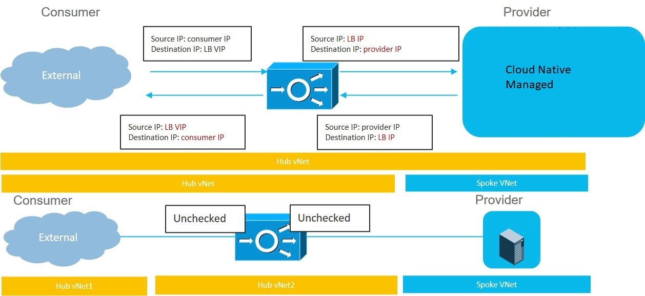

Passthrough Rules

When redirect is enabled, the rules in the NSGs (Network Security Groups) attached to the service devices are updated to permit traffic from consumer to provider. These rules are called “passthrough rules". In general, the passthrough rule is to permit traffic from consumer IP to provider IP. If the destination IP is an application load balancer (ALB) VIP, the rule is to permit traffic from consumer IP to the ALB VIP.

Redirect Programming

Redirect programming depends on the classification of the destination EPG (tag-based or subnet-based):

  • For a subnet-based EPG, subnets of the destination EPGs are used to program redirects

  • For a tag-based EPGs, CIDRs of the destination VNet are used to program redirects

As a result of this, the redirect affects traffic from other EPGs going to the same destination in the redirect, even if the EPG is not part of the service graph with the redirect. Traffic from EPGs that are not part of the redirect will also get redirected to the service device.

The following table describes how redirect is programmed in different scenarios.

Consumer

Provider

Redirect on Consumer VNet

Redirect on Provider VNet

Tag-based

Tag-based

Redirect for the provider are the CIDRs of the provider's VNet

Redirect for the consumer are the CIDRs of the consumer's VNet

Tag-based

Subnet-based

Redirect for the provider are the subnets of the provider

Redirect for the consumer are the CIDRs of the consumer's VNet

Subnet-based

Tag-based

Redirect for the provider are the CIDRs of the provider's VNet

Redirect for the consumer are the subnets of the consumer

Subnet-based

Subnet-based

Redirect for the provider are the subnets of the provider

Redirect for the consumer are the subnets of the consumer

Redirect Policy

To support the Layer 4 to Layer 7 Service Redirect feature, a new redirect flag is now available for service device connectors. The following table provides information on the existing and new flags for the service device connectors.

ConnType

Description

redir

This value means the service node is in redirect node for that connection. This value is only available or valid for third-party firewalls and Network Load Balancers.

snat

This value tells the service graph that the service node is performing source NAT on traffic. This value is only available or valid for the provider connector of third-party firewalls and only on the provider connector of a node.

snat_dnat

This value tells the service graph that the service node is performing both source NAT and destination NAT on traffic. This value is only available or valid for the provider connector of third-party firewalls and only on the provider connector of a node.

none

Default value.

Workflow for Configuring Redirect

Following is the typical workflow for configuring redirect:

  1. Create one or more service devices to use with the service graph:

    • Network load balancer (NLB)

    • Application load balancer (ALB)

    • Third-party firewall

  2. Create a service graph and select the appropriate service devices for this particular service graph.

    You will configure redirect at this point in the procedures:

    1. Drag and drop a network load balancer, application load balancer, or firewall icon to the Drop Device area to select that service device for the service graph.

    2. To enable the redirect feature, in the Service Node window that appears, check the box next to the Redirect option under the Consumer Connector Type and/or under the Provider Connector Type areas, depending on where you want to enable the redirect function.


      Note

      Even though you might have an application load balancer in the service graph, you cannot enable redirect on an application load balancer service device.


    3. Complete the remaining configurations in the Service Node window, then click Add.

  3. Configure the EPG communication, where you create a contract between the consumer and the provider EPGs.

  4. Attach the service graph to the contract.

  5. Configure the service device parameters.

Example Use Cases

Following are several example use cases:

Spoke to Internet

In this use case, the consumer VNet (with consumer VMs) and the hub VNet are peered using VNet peering. A network load balancer is also deployed, fronting two firewalls for scaling. In this use case, the consumer VMs need access to the internet for a certain reason, such as patch updates. In the consumer VNet, the route table is modified to include a redirect for the internet in this case, and traffic is redirected to the NLB in front of firewalls in the hub VNet. Any traffic from this consumer that is part of the service graph that is going to the internet goes to the NLB as the next-hop. With VNet peering, traffic first goes to the NLB, then the NLB forwards the traffic to one of the firewalls in the back end. The firewalls also perform source network address translation (SNAT) when sending traffic to the internet.

Ensure that all the Layer 4 to Layer 7 services devices used in this use case have dedicated subnets.

The following figure shows the packet flow for this use case.

The following figure shows the service graph for this use case.

As part of the redirect configuration for this use case, you would make the following selections:

  • In the Create Device window

    • In the Tenant field, choose the infra tenant.

    • Choose the type of service device in the Service Type field:

      • Choose Network Load Balancer as the Service Type, and in the Subnets area, click Add Subnet, then choose the appropriate region, cloud context profille, and the subnet created in the overlay-2 VRF.

      • Choose Third-Party Firewall as the Service Type, and in the VRF field, choose the overlay-2 VRF.

  • In the Create Service Graph window, drag-and-drop the following service devices, in this order:

    • Network Load Balancer

    • Third-Party Firewall

  • In the Service Node window for the Network Load Balancer:

    • In the Consumer Connector Type field, place a check in the box next to the Redirect option to enable the redirect function on the consumer side.

    • In the Provider Connector Type field, leave the boxes unchecked.

  • In the Service Node window for the Third-Party Firewall:

    • In the Consumer Connector Type field, leave the boxes unchecked.

    • Because the firewall performs SNAT when sending traffic to the internet in this use case, in the Provider Connector Type field, place a check in the box next to the SNAT option.

Spoke to Spoke

In this use case, traffic flows from spoke to spoke, through the hub firewall fronted by a hub NLB. Consumer endpoints are in the consumer VNet, and the provider VNet has VMs fronted by an internal NLB (or a third-party load balancer). The egress route table is modified in the consumer and provider VNets so that traffic is redirected to the firewall device fronted by the NLB. Redirect is applied in both directions in this use case.

Ensure that all the Layer 4 to Layer 7 services devices used in this use case have dedicated subnets.

The following figure shows the packet flow for this use case.

The following figure shows the service graph for this use case.

As part of the redirect configuration for this use case, you would make the following selections:

  • In the Create Device window, first create the service devices for the hub VNet:

    • In the Tenant field, choose the infra tenant.

    • Choose the type of service device in the Service Type field:

      • Choose Network Load Balancer as the Service Type, and in the Subnets area, click Add Subnet, then choose the appropriate region, cloud context profile, and the subnet created in the overlay-2 VRF.

      • Choose Third-Party Firewall as the Service Type, and in the VRF field, choose the overlay-2 VRF.

  • In the Create Device window, next create the service devices for the provider VNet:

    • In the Tenant field, choose the provider tenant.

    • In the Service Type field, choose Network Load Balancer, and in the Subnets area, click Add Subnet, then choose the appropriate region, cloud context profille, and the subnet for the provider VRF.


      Note

      A third-party load balancer can be used in place of an internal NLB. Choose Third-party load balancer as the Service Type. Choose the VRF and set the interface(s) details by clicking Add Interface.


  • In the Create Service Graph window, drag-and-drop the following service devices, in this order:

    • Network Load Balancer (for the hub VNet)

    • Third-Party Firewall (for the hub VNet)

    • Network Load Balancer or Third-Party Load Balancer (for the provider VNet)

  • In the Service Node window for the Network Load Balancer in the hub VNet:

    • In the Consumer Connector Type field, place a check in the box next to the Redirect option to enable the redirect function on the consumer side.

    • In the Provider Connector Type field, place a check in the box next to the Redirect option to enable the redirect function on the provider side.

  • In the Service Node window for the Third-Party Firewall, leave the boxes unchecked for the Consumer Connector Type and the Provider Connector Type.

  • In the Service Node window for the Network Load Balancer in the provider VNet, leave the boxes unchecked for the Consumer Connector Type and the Provider Connector Type.


    Note

    Ensure SNAT is configured on the third-party load balancers.


Inter-Region Spoke to Spoke

In this use case, both regions must have service devices. The consumer VNet is in region 1, the provider is stretched across both regions (regions 1 and 2), and some endpoints are in region 1 and some endpoints are in region 2. Different redirects are programmed for local provider endpoints and for remote region endpoints. In this case, the firewall that is used will be the firewall that is closest to the provider endpoint side.

Ensure that all the Layer 4 to Layer 7 services devices used in this use case have dedicated subnets.

For example, consider the two subnets in the consumer VNet (VRF 1) egress route table (RT):

  • 30.20.10.0/24 (NLB in region 1 [R1])

  • 50.20.10.0/24 (NLB in region 2 [R2])

Assume the consumer wants to send traffic to the provider VMs 30.20.10.0/24, which are local to it. In that case, traffic will get redirected to the region 1 hub NLB and firewall, and will then go to the provider.

Now assume the consumer wants to send traffic to the provider VMs 50.20.10.0/24. In this case, the traffic will get redirected to the region 2 hub NLB and firewall, because that firewall is local to the provider endpoint.

The following figure shows the packet flow for this use case.

The following figure shows the service graph for this use case.

As part of the redirect configuration for this use case, you would make the following selections:

  • In the Create Device window, first create the service devices for the hub VNet:

    • In the Tenant field, choose the infra tenant.

    • Choose the type of service device in the Service Type field:

      • Choose Network Load Balancer as the Service Type, and in the Subnets area, click Add Subnet, then choose the appropriate region, cloud context profile, and the subnet created in the overlay-2 VRF.

      • Choose Third-Party Firewall as the Service Type, and in the VRF field, choose the overlay-2 VRF.

  • In the Create Service Graph window, drag-and-drop the following service devices, in this order:

    • Network Load Balancer

    • Third-Party Firewall

  • In the Service Node window for the hub NLB:

    • In the Consumer Connector Type field, place a check in the box next to the Redirect option to enable the redirect function on the consumer side.

    • In the Provider Connector Type field, place a check in the box next to the Redirect option to enable the redirect function on the provider side.

  • In the Service Node window for the Third-Party Firewall, leave the boxes unchecked for the Consumer Connector Type and the Provider Connector Type.

In the above use case, the provider VMs can also be front-ended by a cloud native or third-party load balancer.

Internet to Spoke (Inter-VRF)

In this use case, traffic coming from the internet needs to go through the firewall before hitting the provider endpoints. Redirect is not used in this use case.


Note

The general term "external load balancer" is used in this section because in this use case, the external load balancer could be either an NLB, ALB or a third-party load balancer. The following examples provide configurations using an ALB, but keep in mind that the external load balancer could be an NLB or a third-party load balancer instead.


The external load balancer exposes the service through VIP. Internet traffic is directed to that VIP, then external load balancers direct traffic to the firewalls in the backend pool (the external load balancers have the firewall's untrusted interface as its backend pool). The firewall performs SNAT and DNAT, and the traffic goes to the internal NLB VIP. The internal NLB then sends traffic to one of the provider endpoints.

Ensure that all the Layer 4 to Layer 7 services devices used in this use case have dedicated subnets.

The following figure shows the packet flow for this use case.

The following figure shows the service graph for this use case.

As part of the redirect configuration for this use case, you would make the following selections:

  • In the Create Device window, first create the service devices for the hub VNet:

    • In the Tenant field, choose the infra tenant.

    • Choose the type of service device in the Service Type field:

      • Choose Application Load Balancer or Network Load Balancer as the Service Type, and in the Subnets area, click Add Subnet, then choose the appropriate region, cloud context profile, and the subnet created in the overlay-2 VRF.

      • Choose Third-Party Firewall as the Service Type, and in the VRF field, choose the overlay-2 VRF.

      • Choose Third-Party Load Balancer as the Service Type, and choose the VRF and set the interface(s) details by clicking Add Interface.

  • In the Create Device window, next create the service devices for the provider VNet:

    • In the Tenant field, choose the provider tenant.

    • In the Service Type field, choose Network Load Balancer, and in the Subnets area, click Add Subnet, then choose the appropriate region, cloud context profille, and the subnet for the provider VRF.

  • In the Create Service Graph window, drag-and-drop the following service devices, in this order:

    • Network Load Balancer or Application Load Balancer (for the hub VNet)

    • Third-Party Firewall (for the hub VNet)

    • Network Load Balancer or Third-Party Load Balancer (for the provider VNet)

  • In the Service Node window for the Network Load Balancer or Application Load Balancer for the hub VNet, leave the boxes unchecked for the Consumer Connector Type and the Provider Connector Type.

  • In the Service Node window for the Third-Party Firewall:

    • In the Consumer Connector Type field, leave the boxes unchecked.

    • Because the firewall performs SNAT and DNAT when sending traffic to the internet in this use case, in the Provider Connector Type field, place a check in the box next to the SNAT and DNAT options.

  • In the Service Node window for the Network Load Balancer for the provider VNet, leave the boxes unchecked for the Consumer Connector Type and the Provider Connector Type.


    Note

    Ensure SNAT is configured on the third-party load balancers.


High Availability Support for Third-Party Load Balancer

In this use case, traffic coming from the internet needs to go through the third-party load balancer before hitting the provider endpoints. Redirect is not used in this use case.

The third-party load balancer is configured as the backend pool of the NLB. Secondary IP addresses of the devices act as the target for the NLBs. You can choose to add either primary or secondary IP address (or both) as the target for the NLBs. The third-party load balancer VMs are deployed in active-active mode only. Third-party load balancers can not be used in active-standby high availability configuration.

Ensure that the third-party load balancers and the network load balancers have dedicated subnets.

The following figure shows the service graph for this use case.

As part of the configuration for this use case, you would make the following selections:

  • In the Create Device window, first create the service devices for the hub VNet:

    • In the Tenant field, choose the infra tenant.

    • Choose the type of service device in the Service Type field:

      • Choose Network Load Balancer as the Service Type, and in the Subnets area, click Add Subnet, then choose the appropriate region, cloud context profile, and the subnet created in the overlay-2 VRF.

      • Choose Third-Party Load Balancer as the Service Type, and choose the VRF and set the interface(s) details by clicking Add Interface.

  • In the Create Service Graph window, drag-and-drop the following service devices, in this order:

    • Network Load Balancer

    • Third-Party Load Balancer


    Note

    Ensure that the Network Load Balancer and the Third-Party Load Balancer are in the same VNet.


  • In the Service Node window for the Network Load Balancer for the hub VNet, leave the boxes unchecked for the Consumer Connector Type and the Provider Connector Type.


    Note

    Ensure SNAT is configured on the third-party load balancers.


Consumer and Provider EPGs in Two Separate VNets

This use case is an example configuration with two VNets, with a consumer EPG and provider EPG in separate VNets.

  • A frontend ALB, firewall, and internal NLB are inserted between the consumer and provider EPGs.

  • A consumer endpoint sends traffic to the frontend ALB VIP and it is forwarded to the firewall.

  • The firewall performs SNAT and DNAT, and the traffic flows to internal NLB VIP.

  • The internal NLB load balances the traffic to the backend provider endpoints.

In this use case, a third-party load balancer can be used in place of the frontend ALB or an internal NLB. Ensure that all the Layer 4 to Layer 7 services devices used in this use case have dedicated subnets.

In the figure:

  • The consumer EPG is in a consumer VNet.

  • The provider EPG and all the service devices are in the provider VNet.

  • The application load balancer, network load balancer (or third-party load balancer), and firewall need to have their own subnet in the VNet.

Packet flow for both the directions is shown in the following figure:

Hub VNet with Consumer and Provider EPGs in Two Separate VNets

This use case is an example configuration with three VNets: a hub VNet, and a consumer EPG and provider EPG in two separate VNets.

  • A frontend ALB and firewall are inserted within the hub VNet, which is between the consumer and provider EPGs.

  • An internal NLB is inserted in the provider EPG.

  • A consumer endpoint sends traffic to the frontend ALB VIP and it is forwarded to the firewall.

  • The firewall performs SNAT and DNAT, and the traffic flows to internal NLB VIP.

  • The internal NLB load balances the traffic to the backend provider endpoints.

In this use case, a third-party load balancer can be used in place of the frontend ALB or an internal NLB. Ensure that all the Layer 4 to Layer 7 services devices used in this use case have dedicated subnets.

In the figure:

  • The consumer EPG is in a consumer VNet.

  • The provider EPG and the internal NLB are in the provider VNet.

  • The frontend ALB and firewall are in the hub VNet

  • The application load balancer, network load balancer (or third-party load balancer), and firewall need to have their own subnet in the VNet.

Packet flow for both the direction is shown in the following figure:

Example Use Cases for Service Graphs with Cloud Native and Third-Party Services

Following are several example use case for service graphs with cloud native and third-party services, with and without redirect. Refer to Using Service Graphs with Cloud Native and Third-Party Services for more information and for guidelines and limitations.

Example Use Cases Without Redirect

Following are several example use case for service graphs with cloud native and third-party services without redirect.

You will be configuring cloud service EPGs as part of the process for each of these use cases. You must have the NSG-per-subnet configuration enabled if you are configuring cloud service EPGs. See Security Groups and Cloud Service Endpoint Groups for more information.


Note

For each of the following use cases, a similar topology with a single node, two node and three node service graph with the service EPG as the provider can be supported for East-West traffic in the cloud. In these use cases, the consumer will be a cloud EPG and the load balancer used will be an internal load balancer.


Single-Node Service Graph for Internet Inbound Traffic: Non-Managed Service EPG as Provider

This use case has a single-node service graph, where the service node is a load balancer (application load balancer, network load balancer, or third-party load balancer).

In this use case, the service EPG is the provider, and an external EPG is configured on the consumer side. The service EPG can be in the hub or spoke VNets. The service endpoints are learned dynamically and are added to the application load balancer or network load balancer.

To configure this use case:

  1. Create the external EPG on the consumer side.

    See Creating an External EPG Using the Cisco Cloud APIC GUI for those procedures. Select the infra tenant for this external EPG.

  2. Create the service EPG on the provider side and assign the appropriate deployment type and access type to the service EPG.

    See Creating a Service EPG Using the Cisco Cloud APIC GUI for those procedures, using these settings:

    • Service Type: Any supported service type, depending on the deployment type (see Cloud Service Endpoint Groups for more information). For example, Azure Storage would be a supported service type with a Cloud Native deployment type.

    • Deployment type: Cloud Native or Third-Party

    • Access type: Private

  3. Configure the service graph.

    See Creating Service Devices Using The Cloud APIC GUI for those procedures.

    Make the following selections:

    • In the Create Device window, create the service devices for the hub VNet:

      • In the Tenant field, choose the infra tenant.

      • Choose Application Load Balancer or Network Load Balancer as the Service Type, and in the Subnets area, click Add Subnet, then choose the appropriate region, cloud context profile, and the subnet created in the overlay-2 VRF.

    • In the Create Service Graph window, drag-and-drop the Application Load Balancer or Network Load Balancer.

    • In the Service Node window for the Application Load Balancer or Network Load Balancer for the hub VNet, leave the boxes unchecked for the Consumer Connector Type and the Provider Connector Type.

  4. Deploy the Layer 4 to Layer 7 services.

    See Deploying Layer 4 to Layer 7 Services Using the Cisco Cloud APIC GUI for those procedures. Attach the contract that exists between the consumer and provider to the service graph.

Single-Node Service Graph for Internet Inbound Traffic: Cloud Native Service EPG as Provider

This use case has a single-node service graph, where the service node is a load balancer (application load balancer, network load balancer, or third-party load balancer).

In this use case, the service EPG is the provider, and an external EPG is configured on the consumer side. The service EPG can be in the hub or spoke VNets.

To configure this use case:

  1. Create the external EPG on the consumer side.

    See Creating an External EPG Using the Cisco Cloud APIC GUI for those procedures. Select the infra tenant for this external EPG.

  2. Create the service EPG on the provider side and assign the appropriate deployment type and access type to the service EPG.

    See Creating a Service EPG Using the Cisco Cloud APIC GUI for those procedures, using these settings:

    • Service Type: Any supported service type, depending on the deployment type (see Cloud Service Endpoint Groups for more information). For example, Azure ApiManagement Services would be a supported service type with a Cloud Native Managed deployment type.

    • Deployment type: Cloud Native Managed

    • Access type: Public and Private

  3. Configure the service graph.

    See Creating Service Devices Using The Cloud APIC GUI for those procedures.

    Make the following selections:

    • In the Create Device window, create the service devices for the hub VNet:

      • In the Tenant field, choose the infra tenant.

      • Choose Application Load Balancer as the Service Type, and in the Subnets area, click Add Subnet, then choose the appropriate region, cloud context profile, and the subnet created in the overlay-2 VRF.

    • In the Create Service Graph window, drag-and-drop the Application Load Balancer.

    • In the Service Node window for the Application Load Balancer for the hub VNet, leave the boxes unchecked for the Consumer Connector Type and the Provider Connector Type.

  4. Deploy the Layer 4 to Layer 7 services.

    See Deploying Layer 4 to Layer 7 Services Using the Cisco Cloud APIC GUI for those procedures. Attach the contract that exists between the consumer and provider to the service graph.

Two-Node Service Graph for Internet Inbound Traffic: Cloud Native Managed Service EPG as Provider

This use case has a two-node service graph, where the service nodes are a network load balancer and a firewall. Because this two-node service graph doesn't use redirect, SNAT+DNAT is performed on the firewall. The DNATed address is assumed to be a network load balancer or an equivalent service. For this use case, the service graph will only establish route reachability to the load balancer's subnet.

In this use case, the service EPG is the provider, and an external EPG is configured on the consumer side. The service EPG can be in the hub or spoke VNets.

These actions take place in this use case, as shown in the following figure:

  1. Traffic is destined to the network load balancer public VIP, which then load balances the traffic to the firewall (DNAT).

  2. SNAT+DNAT is performed on the firewall.

  3. For the return traffic, Azure translates the source IP to the network load balancer public VIP.

To configure this use case:

  1. Create the external EPG on the consumer side.

    See Creating an External EPG Using the Cisco Cloud APIC GUI for those procedures. Select the infra tenant for this external EPG.

  2. Create the service EPG on the provider side and assign the appropriate deployment type and access type to the service EPG.

    See Creating a Service EPG Using the Cisco Cloud APIC GUI for those procedures, using these settings:

    • Service Type: Any supported service type, depending on the deployment type (see Cloud Service Endpoint Groups for more information). For example, Azure Kubernetes Services (AKS) would be a supported service type with a Cloud Native Managed deployment type.

    • Deployment type: Cloud Native Managed

    • Access type: Private

  3. Configure the service graph.

    See Creating Service Devices Using The Cloud APIC GUI for those procedures.

    As part of the redirect configuration for this use case, you would make the following selections:

    • In the Create Device window

      • In the Tenant field, choose the infra tenant.

      • Choose the type of service device in the Service Type field:

        • Choose Network Load Balancer as the Service Type, and in the Subnets area, click Add Subnet, then choose the appropriate region, cloud context profille, and the subnet created in the overlay-2 VRF.

        • Choose Third-Party Firewall as the Service Type, and in the VRF field, choose the overlay-2 VRF.

    • In the Create Service Graph window, drag-and-drop the following service devices, in this order:

      • Network Load Balancer

      • Third-Party Firewall

    • In the Service Node window for the Network Load Balancer, leave the boxes unchecked for the Consumer Connector Type and the Provider Connector Type.

    • In the Service Node window for the Third-Party Firewall:

      • In the Consumer Connector Type field, leave the boxes unchecked.

      • Because the firewall performs SNAT and DNAT when sending traffic to the internet in this use case, in the Provider Connector Type field, place a check in the box next to the SNAT and DNAT options.

  4. Deploy the Layer 4 to Layer 7 services.

    See Deploying Layer 4 to Layer 7 Services Using the Cisco Cloud APIC GUI for those procedures. Attach the contract that exists between the consumer and provider to the service graph.

Three-Node Service Graph for Internet Inbound Traffic: Cloud Native Managed Service EPG as Provider

This use case has a three-node service graph, where the service nodes are:

  • First service device: Network load balancer in the hub VNet

  • Second service device: Firewall in the hub VNet

  • Third service device: Third-party load balancer in the hub VNet or spoke VNet

Because this three-node service graph doesn't use redirect, SNAT+DNAT is performed on the firewall. The DNATed address is assumed to be a load balancer or an equivalent service.

In this use case, the service EPG is the provider, and an external EPG is configured on the consumer side. The service EPG can be in the hub or spoke VNets.

These actions take place in this use case, as shown in the following figure:

  1. Traffic is destined to the first service device, the network load balancer public VIP, which then load balances the traffic to the firewall (DNAT).

  2. SNAT+DNAT is performed on the firewall, which is the second service device.

  3. Traffic moves to the third service device, the third-party load balancer, which has SNAT configured.

  4. For the return traffic, Azure translates the source IP to the network load balancer public VIP.

To configure this use case:

  1. Create the external EPG on the consumer side.

    See Creating an External EPG Using the Cisco Cloud APIC GUI for those procedures. Select the infra tenant for this external EPG.

  2. Create the service EPG on the provider side and assign the appropriate deployment type and access type to the service EPG.

    See Creating a Service EPG Using the Cisco Cloud APIC GUI for those procedures, with these settings:

    • Service Type: Any supported service type, depending on the deployment type (see Cloud Service Endpoint Groups for more information). For example, Azure ApiManagement Services would be a supported service type with a Cloud Native Managed deployment type.

    • Deployment type: Cloud Native Managed

    • Access type: Private

  3. Configure the service graph.

    See Creating Service Devices Using The Cloud APIC GUI for those procedures.

    As part of the redirect configuration for this use case, you would make the following selections:

    • In the Create Device window, first create the service devices for the hub VNet:

      • In the Tenant field, choose the infra tenant.

      • Choose the type of service device in the Service Type field:

        • For the first service device, choose Application Load Balancer as the Service Type, and in the Subnets area, click Add Subnet, then choose the appropriate region, cloud context profile, and the subnet created in the overlay-2 VRF.

        • For the second service device, choose Third-Party Firewall as the Service Type, and in the VRF field, choose the overlay-2 VRF.

        • If the third service device is in the hub VNet, choose Third-Party Load Balancer as the Service Type, and choose the VRF and set the interface(s) details by clicking Add Interface.

    • In the Create Device window, next create the service devices for the provider VNet, if necessary (if the third service device is in the provider VNet):

      • In the Tenant field, choose the provider tenant.

      • In the Service Type field, choose Third-Party Load Balancer, and in the Subnets area, click Add Subnet, then choose the appropriate region, cloud context profille, and the subnet for the provider VRF.

    • In the Create Service Graph window, drag-and-drop the following service devices, in this order:

      • Application Load Balancer (for the hub VNet)

      • Third-Party Firewall (for the hub VNet)

      • Third-Party Load Balancer (for the hub or provider VNet)

    • In the Service Node window for the Application Load Balancer for the hub VNet, leave the boxes unchecked for the Consumer Connector Type and the Provider Connector Type.

    • In the Service Node window for the Third-Party Firewall:

      • In the Consumer Connector Type field, leave the boxes unchecked.

      • Because the firewall performs SNAT and DNAT when sending traffic to the internet in this use case, in the Provider Connector Type field, place a check in the box next to the SNAT and DNAT options.

    • Ensure SNAT is configured on the third party load balancers.

  4. Deploy the Layer 4 to Layer 7 services.

    See Deploying Layer 4 to Layer 7 Services Using the Cisco Cloud APIC GUI for those procedures. Attach the contract that exists between the consumer and provider to the service graph.

Example Use Cases With Redirect

Following are several example use case for service graphs with cloud native and third-party services with redirect.

You will be configuring cloud service EPGs as part of the process for each of these use cases. You must have the NSG-per-subnet configuration enabled if you are configuring cloud service EPGs. See Security Groups and Cloud Service Endpoint Groups for more information.

Two-Node Service Graph for Internet Outbound

This use case has a two-node service graph, where the service nodes are a network load balancer and a firewall. Redirect is enabled on the consumer side in this use case, and SNAT is enabled on the firewall.

In this use case, the service EPG is the consumer, and an external EPG is configured on the provider side.


Note

We recommend that you do not use 0.0.0.0/0 in an external EPG if the Layer 4 to Layer 7 service graph is used for PaaS that uses its own UDR for internet reachability.


These actions take place in this use case, as shown in the following figure:

  1. Traffic is redirected to the network load balancer, which then load balances the traffic to the firewall.

  2. SNAT is performed on the firewall.

  3. The return traffic comes back to the firewall SNAT IP address.

  4. At this point in the return direction, the return traffic doesn't go through the network load balancer.

To configure this use case:

  1. Create the external EPG on the provider side.

    See Creating an External EPG Using the Cisco Cloud APIC GUI for those procedures.

    • Select the infra tenant for this external EPG.

    • Do not configure the external EPG with the 0.0.0.0/0 subnet.

  2. Create the service EPG on the consumer side and assign the appropriate deployment type and access type to the service EPG.

    See Creating a Service EPG Using the Cisco Cloud APIC GUI for those procedures, with these settings:

    • Service Type: Any supported service type, depending on the deployment type (see Cloud Service Endpoint Groups for more information). For example, Azure Kubernetes Services (AKS) would be a supported service type with a Cloud Native Managed deployment type.

    • Deployment type: Cloud Native Managed

    • Access type: Private

  3. Configure the service graph.

    See Creating Service Devices Using The Cloud APIC GUI for those procedures.

    As part of the redirect configuration for this use case, you would make the following selections:

    • In the Create Device window

      • In the Tenant field, choose the infra tenant.

      • Choose the type of service device in the Service Type field:

        • Choose Network Load Balancer as the Service Type, and in the Subnets area, click Add Subnet, then choose the appropriate region, cloud context profille, and the subnet created in the overlay-2 VRF.

        • Choose Third-Party Firewall as the Service Type, and in the VRF field, choose the overlay-2 VRF.

    • In the Create Service Graph window, drag-and-drop the following service devices, in this order:

      • Network Load Balancer

      • Third-Party Firewall

    • In the Service Node window for the Network Load Balancer:

      • In the Consumer Connector Type field, place a check in the box next to the Redirect option to enable the redirect function on the consumer side.

      • In the Provider Connector Type field, leave the boxes unchecked.

    • In the Service Node window for the Third-Party Firewall:

      • In the Consumer Connector Type field, leave the boxes unchecked.

      • Because the firewall performs SNAT when sending traffic to the internet in this use case, in the Provider Connector Type field, place a check in the box next to the SNAT option.

  4. Deploy the Layer 4 to Layer 7 services.

    See Deploying Layer 4 to Layer 7 Services Using the Cisco Cloud APIC GUI for those procedures. Attach the contract that exists between the consumer and provider to the service graph.

Two-Node Service Graph for East-West

This use case has a two-node service graph, where the service nodes are a network load balancer and a firewall. Redirect is enabled on both the consumer and the provider side in this use case.

In this use case, the consumer and provider could be cloud EPGs or service EPGs.

These actions take place in this use case, as shown in the following figure:

  1. Traffic is redirected to the network load balancer, which then load balances the traffic to the firewall.

  2. SNAT is not performed on the firewall in this use case.

  3. The return traffic is redirected to the network load balancer, which then load balances the traffic to the firewall.

  4. At this point in the return direction, the return traffic comes back to the consumer.

To configure this use case:

  1. If you are using service EPGs for the consumer or provider, create the service EPG and assign the appropriate deployment type and access type to the service EPG.

    See Creating a Service EPG Using the Cisco Cloud APIC GUI for those procedures, with these settings:

    • The service EPG as the consumer could have the following settings:

      • Service Type: Any supported service type, depending on the deployment type (see Cloud Service Endpoint Groups for more information). For example, Azure Kubernetes Services (AKS) would be a supported service type with a Cloud Native Managed deployment type.

      • Deployment type: Cloud Native Managed

      • Access type: Private

    • The service EPG as the provider could have the following settings:

      • Service Type: Any supported service type, depending on the deployment type (see Cloud Service Endpoint Groups for more information). For example, Azure Storage File would be a supported service type with a Cloud Native deployment type.

      • Deployment type: Cloud Native

      • Access type: Private

  2. Configure the service graph.

    See Creating Service Devices Using The Cloud APIC GUI for those procedures.

    As part of the redirect configuration for this use case, you would make the following selections:

    • In the Create Device window, first create the service devices for the hub VNet:

      • In the Tenant field, choose the infra tenant.

      • Choose the type of service device in the Service Type field:

        • Choose Network Load Balancer as the Service Type, and in the Subnets area, click Add Subnet, then choose the appropriate region, cloud context profile, and the subnet created in the overlay-2 VRF.

        • Choose Third-Party Firewall as the Service Type, and in the VRF field, choose the overlay-2 VRF.

    • In the Create Service Graph window, drag-and-drop the following service devices, in this order:

      • Network Load Balancer

      • Third-Party Firewall

    • In the Service Node window for the hub NLB:

      • In the Consumer Connector Type field, place a check in the box next to the Redirect option to enable the redirect function on the consumer side.

      • In the Provider Connector Type field, place a check in the box next to the Redirect option to enable the redirect function on the provider side.

    • In the Service Node window for the Third-Party Firewall, leave the boxes unchecked for the Consumer Connector Type and the Provider Connector Type.

  3. Deploy the Layer 4 to Layer 7 services.

    See Deploying Layer 4 to Layer 7 Services Using the Cisco Cloud APIC GUI for those procedures. Attach the contract that exists between the consumer and provider to the service graph.

Two-Node Service Graph for East-West with SNAT Option

This use case has a two-node service graph, where the service nodes are a network load balancer and a firewall. Redirect is enabled only on the consumer side and SNAT is enabled on the firewall in this use case.

In this use case, the consumer and provider could be cloud EPGs or service EPGs.

These actions take place in this use case, as shown in the following figure:

  1. Traffic is redirected to the network load balancer, which then load balances the traffic to the firewall.

  2. SNAT is performed on the firewall.

  3. The return traffic comes back to the firewall SNAT IP address.

  4. At this point in the return direction, the return traffic doesn't go through the network load balancer.

To configure this use case:

  1. If you are using service EPGs for the consumer or provider, create the service EPG and assign the appropriate deployment type and access type to the service EPG.

    See Creating a Service EPG Using the Cisco Cloud APIC GUI for those procedures, with these settings:

    • The service EPG as the consumer could have the following settings:

      • Service Type: Any supported service type, depending on the deployment type (see Cloud Service Endpoint Groups for more information). For example, Azure Active Directory Domain Services would be a supported service type with a Cloud Native Managed deployment type.

      • Deployment type: Cloud Native Managed

      • Access type: Private

    • The service EPG as the provider could have the following settings:

      • Service Type: Any supported service type, depending on the deployment type (see Cloud Service Endpoint Groups for more information). For example, Azure Storage File would be a supported service type with a Cloud Native deployment type.

      • Deployment type: Cloud Native

      • Access type: Private

  2. Configure the service graph.

    See Creating Service Devices Using The Cloud APIC GUI for those procedures.

    As part of the redirect configuration for this use case, you would make the following selections:

    • In the Create Device window

      • In the Tenant field, choose the infra tenant.

      • Choose the type of service device in the Service Type field:

        • Choose Network Load Balancer as the Service Type, and in the Subnets area, click Add Subnet, then choose the appropriate region, cloud context profille, and the subnet created in the overlay-2 VRF.

        • Choose Third-Party Firewall as the Service Type, and in the VRF field, choose the overlay-2 VRF.

    • In the Create Service Graph window, drag-and-drop the following service devices, in this order:

      • Network Load Balancer

      • Third-Party Firewall

    • In the Service Node window for the Network Load Balancer:

      • In the Consumer Connector Type field, place a check in the box next to the Redirect option to enable the redirect function on the consumer side.

      • In the Provider Connector Type field, leave the boxes unchecked.

    • In the Service Node window for the Third-Party Firewall:

      • In the Consumer Connector Type field, leave the boxes unchecked.

      • Because the firewall performs SNAT when sending traffic to the internet in this use case, in the Provider Connector Type field, place a check in the box next to the SNAT option.

  3. Deploy the Layer 4 to Layer 7 services.

    See Deploying Layer 4 to Layer 7 Services Using the Cisco Cloud APIC GUI for those procedures. Attach the contract that exists between the consumer and provider to the service graph.

Two-Node Service Graph for Inbound Traffic via Express Route Gateway

This use case has a two-node service graph, where the service nodes are a network load balancer and a firewall. Redirect is enabled on both the consumer and the provider side in this use case.

In this use case, the service EPG is the provider, and the express route is on the consumer side.

These actions take place in this use case, as shown in the following figure:

  1. Traffic is redirected to the network load balancer, which then load balances the traffic to the firewall.

  2. SNAT is not performed on the firewall in this use case.

  3. The return traffic is redirected to the network load balancer, which then load balances the traffic to the firewall.

  4. At this point in the return direction, the return traffic comes back to the consumer.

To configure this use case:

  1. Create the service EPG on the provider side and assign the appropriate deployment type and access type to the service EPG.

    See Creating a Service EPG Using the Cisco Cloud APIC GUI for those procedures, with these settings:

    • Service Type: Any supported service type, depending on the deployment type (see Cloud Service Endpoint Groups for more information). For example, Azure Active Directory Domain Services would be a supported service type with a Cloud Native Managed deployment type.

    • Deployment type: Cloud Native Managed

    • Access type: Private

  2. Deploy the express route gateway on the consumer side.

    See Deploying Express Route Gateway Using Redirect for those procedures.

  3. Configure the service graph.

    See Creating Service Devices Using The Cloud APIC GUI for those procedures.

    As part of the redirect configuration for this use case, you would make the following selections:

    • In the Create Device window

      • In the Tenant field, choose the infra tenant.

      • Choose the type of service device in the Service Type field:

        • Choose Network Load Balancer as the Service Type, and in the Subnets area, click Add Subnet, then choose the appropriate region, cloud context profille, and the subnet created in the overlay-2 VRF.

        • Choose Third-Party Firewall as the Service Type, and in the VRF field, choose the overlay-2 VRF.

    • In the Create Service Graph window, drag-and-drop the following service devices, in this order:

      • Network Load Balancer

      • Third-Party Firewall

    • In the Service Node window for the Network Load Balancer:

      • In the Consumer Connector Type field, place a check in the box next to the Redirect option to enable the redirect function on the consumer side.

      • In the Provider Connector Type field, leave the boxes unchecked.

    • In the Service Node window for the Third-Party Firewall:

      • In the Consumer Connector Type field, leave the boxes unchecked.

      • Because the firewall performs SNAT when sending traffic to the internet in this use case, in the Provider Connector Type field, place a check in the box next to the SNAT option.

  4. Deploy the Layer 4 to Layer 7 services.

    See Deploying Layer 4 to Layer 7 Services Using the Cisco Cloud APIC GUI for those procedures. Attach the contract that exists between the consumer and provider to the service graph.

Two-Node Service Graph for Inbound Traffic via Express Route Gateway with SNAT Option

This use case has a two-node service graph, where the service nodes are a network load balancer and a firewall. Redirect is enabled only on the consumer side and SNAT is enabled on the firewall in this use case.

In this use case, the service EPG is the provider, the express route is on the consumer side.

These actions take place in this use case, as shown in the following figure:

  1. Traffic is redirected to the network load balancer, which then load balances the traffic to the firewall.

  2. SNAT is performed on the firewall.

  3. The return traffic comes back to the firewall SNAT IP address.

  4. At this point in the return direction, the return traffic doesn't go through the network load balancer.

To configure this use case:

  1. Create the service EPG on the provider side and assign the appropriate deployment type and access type to the service EPG.

    See Creating a Service EPG Using the Cisco Cloud APIC GUI for those procedures, with these settings:

    • Service Type: Any supported service type, depending on the deployment type (see Cloud Service Endpoint Groups for more information). For example, Redis Cache would be a supported service type with a Cloud Native Managed deployment type.

    • Deployment type: Cloud Native Managed

    • Access type: Private

  2. Deploy the express route gateway on the consumer side.

    See Deploying Express Route Gateway Using Redirect for those procedures.

  3. Configure the service graph.

    See Creating Service Devices Using The Cloud APIC GUI for those procedures.

    As part of the redirect configuration for this use case, you would make the following selections:

    • In the Create Device window

      • In the Tenant field, choose the infra tenant.

      • Choose the type of service device in the Service Type field:

        • Choose Network Load Balancer as the Service Type, and in the Subnets area, click Add Subnet, then choose the appropriate region, cloud context profille, and the subnet created in the overlay-2 VRF.

        • Choose Third-Party Firewall as the Service Type, and in the VRF field, choose the overlay-2 VRF.

    • In the Create Service Graph window, drag-and-drop the following service devices, in this order:

      • Network Load Balancer

      • Third-Party Firewall

    • In the Service Node window for the Network Load Balancer:

      • In the Consumer Connector Type field, place a check in the box next to the Redirect option to enable the redirect function on the consumer side.

      • In the Provider Connector Type field, leave the boxes unchecked.

    • In the Service Node window for the Third-Party Firewall:

      • In the Consumer Connector Type field, leave the boxes unchecked.

      • Because the firewall performs SNAT when sending traffic to the internet in this use case, in the Provider Connector Type field, place a check in the box next to the SNAT option.

  4. Deploy the Layer 4 to Layer 7 services.

    See Deploying Layer 4 to Layer 7 Services Using the Cisco Cloud APIC GUI for those procedures. Attach the contract that exists between the consumer and provider to the service graph.

Three-Node Service Graph for Inbound Traffic via Express Route Gateway

This use case has a three-node service graph, where the service nodes are:

  • First service device: Network load balancer in the hub VNet

  • Second service device: Firewall in the hub VNet

  • Third service device: Application load balancer in the hub or spoke VNet

Redirect is enabled on both the consumer and the provider side in this use case.

In this use case, the service EPG is the provider. The express route is on the consumer side, and the consumer can could be a cloud EPG or a service EPG.

These actions take place in this use case, as shown in the following figure:

  1. Traffic is redirected to the network load balancer, which then load balances the traffic to the firewall.

  2. SNAT is not performed on the firewall in this use case.

  3. Traffic moves to the third service device, the application load balancer, which has SNAT configured.

  4. The return traffic is redirected to the network load balancer, which then load balances the traffic to the firewall.

  5. At this point in the return direction, the return traffic comes back to the consumer.

To configure this use case:

  1. Create the service EPG on the provider side and assign the appropriate deployment type and access type to the service EPG.

    See Creating a Service EPG Using the Cisco Cloud APIC GUI for those procedures, with these settings:

    • Service Type: Any supported service type, depending on the deployment type (see Cloud Service Endpoint Groups for more information). For example, Azure ApiManagement Services would be a supported service type with a Cloud Native Managed deployment type.

    • Deployment type: Cloud Native Managed

    • Access type: Private

  2. Deploy the express route gateway on the consumer side.

    See Deploying Express Route Gateway Using Redirect for those procedures.

  3. Configure the service graph.

    See Creating Service Devices Using The Cloud APIC GUI for those procedures.

    As part of the redirect configuration for this use case, you would make the following selections:

    • In the Create Device window, first create the service devices for the hub VNet:

      • In the Tenant field, choose the infra tenant.

      • Choose the type of service device in the Service Type field:

        • Choose Network Load Balancer as the Service Type, and in the Subnets area, click Add Subnet, then choose the appropriate region, cloud context profile, and the subnet created in the overlay-2 VRF.

        • Choose Third-Party Firewall as the Service Type, and in the VRF field, choose the overlay-2 VRF.

    • In the Create Device window, next create the service devices for the provider VNet:

      • In the Tenant field, choose the provider tenant.

      • In the Service Type field, choose Application Load Balancer, and in the Subnets area, click Add Subnet, then choose the appropriate region, cloud context profille, and the subnet for the provider VRF.


        Note

        A third party load balancer can be used in place of an internal NLB. Choose Third Party Load Balancer as the Service Type. Choose the VRF and set the interface(s) details by clicking Add Interface.


    • In the Create Service Graph window, drag-and-drop the following service devices, in this order:

      • Network Load Balancer (for the hub VNet)

      • Third-Party Firewall (for the hub VNet)

      • Application Load Balancer (for the provider VNet)

    • In the Service Node window for the Network Load Balancer in the hub VNet:

      • In the Consumer Connector Type field, place a check in the box next to the Redirect option to enable the redirect function on the consumer side.

      • In the Provider Connector Type field, place a check in the box next to the Redirect option to enable the redirect function on the provider side.

    • In the Service Node window for the Third-Party Firewall, leave the boxes unchecked for the Consumer Connector Type and the Provider Connector Type.

    • In the Service Node window for the Network Load Balancer in the provider VNet, leave the boxes unchecked for the Consumer Connector Type and the Provider Connector Type.


      Note

      Ensure SNAT is configured on the third party load balancers.


  4. Deploy the Layer 4 to Layer 7 services.

    See Deploying Layer 4 to Layer 7 Services Using the Cisco Cloud APIC GUI for those procedures. Attach the contract that exists between the consumer and provider to the service graph.

Guidelines and Limitations for Redirect

Following are the guidelines and limitations for redirect:

  • All the Layer 4 to Layer 7 services devices should have their own dedicated subnet.

  • Intra VRF Layer 4 to Layer 7 services redirection within a region:

    • Layer 4 to Layer 7 services redirect is not supported for east-west deployment when the consumer EPG and provider EPG are in the same VNet.

    • Layer 4 to Layer 7 services redirect is supported for north-south deployment if the external EPG is a provider EPG, regardless of whether the consumer EPG and provider EPG are in same VNet or not.

  • Intra-VRF Layer 4 to Layer 7 services redirection across regions:

    • Inter-Region Layer 4 to Layer 7 services redirection are supported. However, the Consumer EPG and the Provider EPG should not stretch.

    • A region shouldn't have both a consumer EPG and a provider EPG in the same VRF. For example, if region 1 has a consumer EPG only and region 2 has a provider EPG only, this is supported, but region 1 can't have both the consumer EPG and the provider EPG.

    • Consumer and Provider EPG should be a subnet-based EPG.

  • For the inter-region service graphs with Layer 4 to Layer 7 services redirection, service devices should be deployed in the provider EPG’s region. If provider EPG is stretched across regions, service devices should be deployed in each region .

  • For the external EPG as provider, service devices need to be deployed in the region local to consumer EPG. If the consumer EPG is stretched across regions, service devices should be deployed in each region.

  • Between a consumer VNet and a provider EPG, only one redirect device can be inserted through a service graph. For example, if consumer EPG1 and consumer EPG2 are in a consumer VNet, and a provider EPG3 is in a provider VNet, you must use the same redirect device for a contract between EPG1 and EPG3, and a contract between EPG2 and EPG3.


    Note

    The limitation is because of the cloud provider allows only one next hop for a given destination in user-defined routes.


  • The following table provides information on the specific redirect configurations that are supported or unsupported, where:

    • NLB stands for network load balancer

    • ALB stands for application load balancer

    • FW stands for firewall


    Note

    Redirection to a third party load balancer is not supported.


    Service Chain Option

    Spoke-to-Spoke

    Spoke-to-External

    (consumer is spoke)

    External-to-Spoke

    (consumer is external)

    Intra-VNet

    Inter-VNet

    Intra-VNet

    Inter-VNet

    Intra-VNet

    Inter-VNet

    NLB/ALB1

    LB(SNAT)1

    Supported

    Supported

    Not supported

    Not supported

    Supported

    Supported

    FW (no SNAT)2

    Not supported

    Supported

    Not supported

    Not supported

    Not supported

    Not supported

    FW (SNAT)3

    Supported

    Supported

    Supported

    Supported

    Not supported

    Not supported

    • NLB2-FW(no SNAT)1

    • NLB2-FW(no SNAT)1-NLB/ALB1

    • NLB2-FW(no SNAT)1-LB(SNAT)1

    Not supported

    Supported

    Not supported

    Not supported

    Not supported

    Not supported

    NLB4-FW(SNAT)5

    Not supported

    Supported

    Supported

    Supported

    Not supported

    Not supported

    NLB/ALB1-FW(SNAT+DNAT)6-NLB/ALB1

    NLB/ALB1-FW(ANT+DNAT)6-LB(SNAT)1

    (No redirection)

    Supported

    Supported

    Not Supported

    Not Supported

    Supported

    Supported

    NLB1-LB(SNAT)1

    (No redirection)

    Supported

    Supported

    Not Supported

    Not Supported

    Supported

    Supported

    1 Unchecked on both consumer and provider connector or options are not applicable for ALB.
    2 Redirect is enabled on both consumer and provider connector.
    3 Redirect is enabled on consumer connector. SNAT is enabled on provider connector.
    4 Redirect is enabled on consumer connector. Unchecked on provider connector.
    5 Unchecked on consumer connector. SNAT is enabled on provider connector.
    6 Unchecked on consumer connector. SNAT+DNAT is enabled on provider connector.

Adding a New CIDR to Overlay-2 Using the Cloud APIC GUI

After an installation, you will see overlay-1 and overlay-2 in the Cisco Cloud APIC. However, on the Azure portal, you will only see overlay-1. This is because overlay-2 is simply a logical extension of overlay-1, and is used to hold additional the CIDRs that you might need if you are deploying firewalls or load balancers on the infra VNet. This section provides instructions for adding new CIDRs to overlay-2.

In some situations, you might have to disable VNet peering before adding new CIDRs or editing existing CIDRs in overlay-2. This is due to a limitation in Azure, where you cannot update a CIDR on a VNet if it has active VNet peerings. To add the CIDRs, you first have to remove VNet peerings for that VNet, then you can update the CIDRs. Once you have updated the CIDRs, you can then re-enable the VNet peerings.

These procedures provide instructions for disabling Hub Network Peering, which removes all of the VNet peerings associated with a particular infra VNet.

  • If you have an additional CIDR already created on the infra VNet, but you simply need to add additional subnets to that existing CIDR, you do not have to disable Hub Network Peering for that particular infra VNet before adding those subnets. To add additional subnets to an existing CIDR:

    1. Navigate to the appropriate cloud context profile in that case (Application Management > Cloud Context Profiles).

    2. Double-click the cloud context profile where you want to add a subnet to an existing CIDR, then go to Step 10 to add the new subnets to an existing CIDR.

  • If you are adding a new CIDR in the infra VNet, or if you are deleting a CIDR or editing a CIDR in the infra VNet in some other way (other than adding subnets), then you must disable Hub Network Peering for that particular infra VNet. You will then re-enable Hub Network Peering again after you have added the CIDR. The following procedure provides those instructions.

Procedure


Step 1

Log in to the Cloud APIC, if you are not logged in already.

Step 2

In the left navigation bar, navigate to Application Management > Cloud Context Profiles.

The existing cloud context profiles are displayed.

Step 3

Double-click the cloud context profile where you want to disable Hub Network Peering.

The overview window for that cloud context profile appears. You should see Enabled in the Hub Network Peering area in this overview window, which indicates that Hub Network Peering is enabled.

Step 4

Click the pencil icon to edit this cloud context profile.

The Edit Cloud Context Profile window appears.

Step 5

In the Edit Cloud Context Profile window, locate the Hub Network Peering field and click the check box to remove the checkmark from the Enabled field.

Disabling the Hub Network Peering option does not remove VNet peering at the global level, but rather removes all of the VNet peerings associated with this particular infra VNet.

Step 6

Click Save.

The overview window for that cloud context profile appears again. You should see Disabled in the Hub Network Peering area in this overview window, which indicates that Hub Network Peering is now disabled.

Step 7

To add a new CIDR, click the pencil icon to edit this cloud context profile again.

The Edit Cloud Context Profile window appears again.

Step 8

Click Add CIDR.

The Add CIDR dialog box appears.

Step 9

Add the new CIDR in the CIDR Block Range field.

Do not click the box in the Primary field (do not put a check in the box next to yes in the Primary field).

Step 10

Click Add Subnet and enter the necessary subnet addresses in the Address field.

Continue to click Add Subnet for additional subnets, if necessary.

Step 11

When you have finished adding all of the necessary information in the Add CIDR window, click Add.

The Edit Cloud Context Profile window appears again.

Step 12

Confirm the information in the Edit Cloud Context Profile window, then click Save.

The overview window for that cloud context profile appears. You should now see the new CIDR listed in the CIDR Block Range area.

Step 13

If you disabled Hub Network Peering at the beginning of these procedures, re-enable it at this time.

  1. Click the pencil icon to edit this cloud context profile.

    The Edit Cloud Context Profile window appears.

  2. In the Edit Cloud Context Profile window, locate the Hub Network Peering field and click the check box to add the checkmark in the Enabled field to re-enable VNet peerings for this particular infra VNet.

  3. Click Save.

    The overview window for that cloud context profile appears again. You should see Enabled in the Hub Network Peering area in this overview window, which indicates that Hub Network Peering is now re-enabled again.

As described previously, if you were to go to the Azure portal at this point, you will see any additional CIDRs and subnets that you added in these procedures in the overlay-1 VNet in Azure, which is the correct and expected behavior.


Deploying a Service Graph

The service graph enables you to define how traffic flows between devices, how the traffic comes into the network, which devices the traffic passes through, and how the traffic leaves the network.

The Service graph can be deployed in two ways:

  • Single node service graph: Only one device is deployed.

  • Multinode service graph: Upto three nodes can be added to the service chain.

Before you can deploy a service graph in either a single node or multinode, you must configure the following:

  1. A tenant

  2. An application profile

  3. A consumer EPG

  4. A provider EPG

  5. A VRF

  6. A cloud context profile

  7. A contract with a filter

Deploying a Service Graph Using the GUI

The following sections describe how to deploy a service graph using the GUI.

Creating Service Devices Using The Cloud APIC GUI

Before you begin

This section explains how to create service devices that can be used in a service graph through the Cisco Cloud APIC GUI.

Procedure

Step 1

Click the Intent icon. The Intent menu appears.

Step 2

Click the drop-down arrow below the Intent search box and choose Application Management.

A list of Application Management options appear in the Intent menu.

Step 3

From the Application Management list in the Intent menu, click Services > Devices > Create Device. The Create Device dialog box appears.

Step 4

Enter the appropriate values in each field as listed in the following Create Device Dialog Box Fields table then continue.

Refer to the following tables for information specific to each type of service device.

  • For an Application Load Balancer, see 4.a.

  • For a Network Load Balancer, see 4.b.

  • For a Third Party Load Balancer, see 4.c.

  • For a Third Party Firewall, see 4.d.

  1. Enter the necessary information for an Application Load Balancer:

    Properties

    Description

    General

    Name

    Enter the name of the device.

    Tenant

    To choose a tenant:

    1. Click Select Tenant. The Select Tenant dialog appears.

    2. From the column on the left, click to choose a tenant.

    3. Click Select. You return to the Create Device dialog box.

    Settings

    Service Type

    Choose the device type:

    • Application Load Balancer

    ALB SKU

    Choose from:

    • Standard

    • Standard V2

    VM Instance Count

    Enter a number in the VM Instance Count text box.

    Note 

    This is applicable only for the Application Gateway.

    VM Instance Size

    Click the radio button for the VM instance size you want to choose: large, medium, or small.

    Note 

    This is applicable only for the Application Gateway.

    Scheme

    Choose Internet Facing or Internal.

    • Internet Facing— This is used for configuring a public IP for the balancer. This is assigned by Azure.

    • Internal—Click to choose either Dynamic or Static under IP Address Assignment.

      • Dynamic—Dynamic IP addresses are assigned by Azure. Dynamic IP addresses change each time the VMs boot up.

      • Static—Enter an IP address based on the CIDRs defined in Cloud Context Profile and check that the IP address is in the same subnet as the ALB.

        ALB SKU Standard supports static and dynamic IP addresses. ALB SKU Standard V2 support static IP addresses only.

    Subnet

    To choose a subnet:

    1. Click Select Region. The Select Region dialog box appears. From the Select Region dialog, click to choose a region in the left column then click Select.

    2. Click Select Cloud Context Profile. The Select Cloud Context Profile dialog box appears.

    3. Click Select Subnet. The Select Subnet dialog box appears. The Static IP Addresses text box is displayed. Enter the IP address of the load balancer. Click the tick mark on the right to confirm.

    4. To add additional subnets, repeat steps a-c.

  2. Enter the necessary information for a Network Load Balancer:

    Table 3. Create Device Dialog Box Fields for Network Load Balancer

    Properties

    Description

    General

    Name

    Enter the name of the load balancer.

    Settings

    Service Type

    Choose the device type:

    • Network Load Balancer

    Allow All Traffic

    Determine if you want to enable the Allow All Traffic option.

    Enabling the Allow All Traffic option will allow all inbound and outbound access to the subnet on which the interface belongs. See About Allow All Traffic Option for more information.

    Note 

    Ensure that this does not present a security risk before enabling this option.

    • If you want to allow all traffic, in the Allow All Traffic area, click the box next to the Enabled field.

    • If you do not want to allow all traffic, in the Allow All Traffic area, leave the box unchecked (unselected) next to the Enabled field.

    Scheme

    Choose Internet Facing or Internal.

    • Internet Facing— This is used for configuring a public IP for the balancer. This is assigned by Azure.

    • Internal—Click to choose either Dynamic or Static under IP Address Assignment.

      • Dynamic—Dynamic IP addresses are assigned by Azure. Dynamic IP addresses change each time the VMs boot up.

      • Static—Enter an IP address based on the CIDRs defined in Cloud Context Profile and check that the IP address is in the same subnet as the NLB. Static IP addresses are associated to load balancers.

        Note 

        Cloud APIC creates standard SKU NLBs only.

    Subnet

    To choose a subnet:

    1. Click Select Region. The Select Region dialog box appears. From the Select Region dialog, click to choose a region in the left column then click Select.

    2. Click Select Cloud Context Profile. The Select Cloud Context Profile dialog box appears.

    3. Click Select Subnet. The Select Subnet dialog box appears. The Static IP Addresses text box is displayed. Enter the IP address of the load balancer. Click the tick mark on the right to confirm.

    4. To add additional subnets, repeat steps a-c.

  3. Enter the necessary information for a Third Party Load Balancer:

    Table 4. Create Device Dialog Box Fields for Third Party Load Balancer

    Properties

    Description

    General

    Name

    Enter the name of the device.

    Tenant

    To choose a tenant:

    1. Click Select Tenant. The Select Tenant dialog appears.

    2. From the column on the left, click to choose a tenant.

    3. Click Select. You return to the Create Device dialog box.

    Settings

    Service Type

    Choose the device type:

    • Third Party Load Balancer

    Creation Mode

    Select Selectors.

    VRF and Interfaces fields are displayed.

    VRF

    Click Select VRF. In the Select VRF dialog box that opens, click to choose a VRF in the left column. Click Select.

    Interface

    Click Add Interface. The Interfaces window is displayed.

    1. Enter a name for the external interface in the Interface Settings field.

    2. Click Add Interface selector.

    3. In the Interface Selector Settings page, enter the name of the interface.

    4. In the Match Expressions field, click Match Expression and select

      • Key: This can be IP, region or a custom based tag selector.

      • Operator: This can be equal, not equals, in, not in, has key, or does not have key.

      • Value: IP address of the external or internal network of third party load balancer.

    5. Click the tick mark to add the interface and then click Save (Interfaces window).

    6. Click Save (Create Device window).

    Click Add Interface and repeat steps a - e to add more interfaces.

    Note 

    Third party load balancer interfaces should be configured with subnet-based selectors when deployed in a multi-node service graph.

  4. Enter the necessary information for a Third Party Firewall:

    Table 5. Create Device Dialog Box Fields for Third Party Firewall

    Properties

    Description

    General

    Name

    Enter the name of the device.

    Settings

    Service Type

    Choose the device type:

    • Third party firewall

    Note 

    Third party firewall cannot be the first device in a multinode service graph.

    VRF

    To choose a VRF:

    1. Click Select VRF. The Select VRF dialog box appears.

    2. From the Select VRF dialog, click to choose a VRF in the left column then click Select.

    Interfaces

    Click Add Interface.

    The Settings page appears.

    1. In the Name field, enter the name of the interface.

    2. Determine if you want to enable the Allow All Traffic option.

      Enabling the Allow All Traffic option will allow all inbound and outbound access to the subnet on which the interface belongs. See About Allow All Traffic Option for more information.

      Note 

      Ensure that this does not present a security risk before enabling this option.

      • If you want to allow all traffic, in the Allow All Traffic area, click the box next to the Enabled field.

      • If you do not want to allow all traffic, in the Allow All Traffic area, leave the box unchecked (unselected) next to the Enabled field.

    3. Click Add Interface Selector.

    4. Enter the name of the interface selector.

    5. Click on Match Expressions and select

      • Key: This can be IP, region or a custom based tag selector.

      • Operator: This can be equal, not equals, in, not in, has key, or does not have key.

      • Value: IP address of the app, web, internal network, management network, or external network.

    6. Click Add.

    7. Repeat steps a - f to add more interfaces.

Step 5

Click Save when finished.

Step 6

The Create Service Graph dialog box appears. Click on the Create another Third Party Firewall to create another device. The Create Device dialog box appears.

Note 

The UI usually asks to create a previously created device. However, on clicking it we return back to the Create Device page. Here we can choose the device that needs to be created. The first device should never be the Third Party Firewall.


Creating a Service Graph Template Using the Cisco Cloud APIC GUI

This section explains how to configure a service graph template for a single node or a multinode, using the Cisco Cloud APIC GUI .

Before you begin

You have already created the devices.

Procedure

Step 1

Click the Intent icon. The Intent menu appears.

Step 2

Click the drop-down arrow below the Intent search box and choose Application Management.

A list of Application Management options appear in the Intent menu.

Step 3

From the Application Management list in the Intent menu, click Services > Service Graph > Create Service Graph. The Create Service Graph pop-up appears. Click on Let's Get Started.

Step 4

Enter the appropriate values in each field as listed in the following Create Service Graph Dialog Box Fields table then continue.

Table 6. Create Service Graph Dialog Box Fields (for single node)

Properties

Description

General

Name

Enter the name of service graph template.

Tenant

To choose a tenant:

  1. Click Select Tenant. The Select Tenant dialog appears.

  2. From the column on the left, click to choose a tenant.

  3. Click Select. You return to the Create Service Graph dialog box.

Description

Enter a description of the service graph template.

Settings

Select a Device

To choose a device:

  1. Click Select Device. The Select Device dialog appears.

  2. From the column on the left, click to choose a device. Drag and drop the device in the Drop Device space below. This will open a small window where the actual device for this device type can be selected.

  3. Click Select. You return to the Create Service Graph dialog box.

Table 7. Create Service Graph Dialog Box Fields (for multinode)

Properties

Description

General

Name

Enter the name of service graph template.

Tenant

To choose a tenant:

  1. Click Select Tenant. The Select Tenant dialog appears.

  2. From the column on the left, click to choose a tenant.

  3. Click Select. You return to the Create Service Graph dialog box.

Description

Enter a description of the service graph template.

Settings: Based on the required topology, drag and drop the devices in the box below

Application Load Balancer

  1. Drag and drop the Application load balancer device into the box below.

  2. In the Service node dialog box, click on the Select Application Load Balancer and click to choose a Application Load Balancer in the left column then click Add.

Third Party Firewall

  1. Drag and drop the Third Party Firewall next to the device in the box below.

  2. In the Service node dialog box, click on the Third Party Firewall and click to choose a Third Party Firewall in the left column then click Add.

    Note 

    Third Party Firewall cannot be the first node on the service graph.

  3. If you want to enable the user-based redirect function on the consumer side of the Third Party Firewall, in the Consumer Connector Type field, place a check in the box next to the Redirect option.

  4. If you want to enable the user-based redirect function on the provider side of the Third Party Firewall, in the Provider Connector Type field, place a check in the box next to the Redirect option.

  5. In the Provider Connector Type, place a check next to the applicable option. Refer to User Defined Routing for information.

  6. Click Add.

Network Load Balancer

  1. Drag and drop the Network load balancer device into the box below.

  2. In the Service node dialog box, click on the Select Network Load Balancer and click to choose a Network Load Balancer in the left column then click Add.

  3. If you want to enable the user-based redirect function on the consumer side of the network load balancer, in the Consumer Connector Type field, place a check in the box next to the Redirect option.

  4. If you want to enable the user-based redirect function on the provider side of the network load balancer, in the Provider Connector Type field, place a check in the box next to the Redirect option.

  5. Click Add.

Third Party Load Balancer

  1. Drag and drop the third party load balancer device into the box below.

  2. In the Service node dialog box, click Select Third Party Load Balancer and click to choose a third party load balancer in the left column.

  3. Click Select Consumer Interface. Select the interface marked as external.

  4. Click Select Provider Interface. Select the interface marked as internal.

  5. Click Add.

Step 5

Click Save when finished.

Step 6

The EPG Communication dialog box appears. Click on the Go to details to verify the Service Graph template.


Deploying Layer 4 to Layer 7 Services Using the Cisco Cloud APIC GUI

This section explains how to deploy Layer 4 to Layer 7 services. This procdure is applicable for single node as well multinode deployments.

Before you begin
  • You have configured the devices.

  • You have configured a service graph.

Procedure

Step 1

Click the Intent icon. The Intent menu appears.

Step 2

Click the drop-down arrow below the Intent search box and choose Configuration.

A list of Configuration options appear in the Intent menu.

Step 3

From the Configuration list in the Intent menu, click EPG Communication. The EPG Communication dialog box appears with the Consumer EPGs, Contract, and Provider EPGs information.

Step 4

To choose a contract:

  1. Click Select Contract. The Select Contract dialog appears.

  2. In the pane on the left side of the Select Contract dialog, click to choose a contract then click Select. The Select Contract dialog box closes.

Step 5

To add a consumer EPG:

  1. Click Add Consumer EPGs. The Select Consumer EPGs dialog appears.

  2. In the pane on the left side of the Select Consumer EPGs dialog, click the check box to choose a cloud EPG (for an internal facing load balancer) or a cloud external EPG (for an internet facing load balancer) then click Select. The Select Consumer EPGs dialog box closes.

Step 6

To add a provider EPG:

  1. Click Add Provider EPGs. The Select Provider EPGs dialog appears.

  2. In the pane on the left side of the Select Provider EPGs dialog, click the check box to choose a provider EPG then click Select. The Select Provider EPGs dialog box closes.

Step 7

To choose a service graph:

  1. From the EPG Communication Configuration dialog, click Select Service Graph. The Select Service Graph dialog box appears.

  2. In the pane on the left side of the Select Service Graph dialog, click to choose a service graph then click Select. The Select Service Graph dialog box closes.

Step 8

Under Service Graph Preview, click Add Cloud Load Balancer Listener. The Add Cloud Load Balancer Listener dialog appears that enables you to add listeners.

Listeners are the ports and protocols that the device will work on.

Step 9

Enter the appropriate values in each field as listed in the following Add Cloud Load Balancer Listener Dialog Box Fields table then continue.

Table 8. Add Cloud Load Balancer Listener Dialog Box Fields For Application Gateway

Properties

Description

Name

Enter the name of the listener.

Port

Enter the port that the device will accept traffic on.

Protocol

For Application Gateway, click to choose HTTP or HTTPS.

Security Policy

Click the drop-down list and choose a security policy (only available when HTTPS is chosen).

SSL Certificate

To choose an SSL certificate(only available when HTTPS is chosen):

  1. Click Add SSL Certificates.

  2. Click to place a check mark in the check box of the certificates you want to add.

  3. Choose a key ring:

    1. Click Select Key Ring. The Select Key Ring dialog appears.

    2. From the Select Key Ring dialog, click to choose a key ring in the left column then click Select. The Select Key Ring dialog box closes.

  4. Click the Certificate Store drop-down list and choose a certificate.

Note 

A listener can have multiple certificates.

Add Rule

To add rule settings to the device listener, click Add Rule. A new row appears in the Rules list an the Rules Settings fields are enabled.

Rule Settings

The Rule Settings pane contains the following options:

  • Name—Enter a name for the rule.

  • Host—Enter a hostname to create a host-based condition. When a request is made for this hostname, the action you specify is taken.

  • Path—Enter a path to create a path-based condition. When a request is made for this path, the action you specify is taken.

  • Type—The action type tells the device which action to take. The action type options:

    • Return fixed response—Returns a response using the following options:

      • Fixed Response Body—Enter a response message.

      • Fixed Response Code—Enter a response code.

      • Fixed response Content-Type—Choose a content type.

    • Forward—Forwards traffic using the following options:

      • Port—Enter the port that the device will accept traffic on.

      • Protocol—Click to choose HTTP or HTTPS.

      • Provider EPG—The EPG with the web server that handles the traffic.

      • EPG—To choose an EPG:

        1. Click Select EPG. The Select EPG dialog box appears.

        2. From the Select EPG dialog ox, click to choose an EPG in the left column then click Select. The Select EPG dialog box closes.

    • Redirect—Redirects requests to another location using the following options:

      • Redirect Code—Click the Redirect Code drop-down list and choose a code.

      • Redirect Hostname—Enter a hostname for the redirect.

      • Redirect Path—Enter a redirect path.

      • Redirect Port—Enter the port that the device will accept traffic on.

      • Redirect Protocol—Click to the Redirect Protocol drop-down list and choose HTTP, HTTPS, or Inherit.

      • Redirect Query—Enter a redirect query.

Health Checks

The Application load balancer performs health checks on its backend pool targets for high availability.This can be configured under health checks:

  • Protocol-Click to choose HTTP or HTTPS.

  • Path - Enter the path. Default is /

  • Port-Enter a port on which health checks should be performed.

  • Advanced Settings-

    Unhealthy Threshold-Configure this threshold to determine when a backend target is advertised as unhealthy.

  • Timeout - Enter the value for health check timeout.

  • Interval-Enter a time in seconds to determine at what intervals checks should be performed.

  • Success Code - Enter the success code. Default is 200-399.

  • Use host from rule - Click on the checkbox if the hostname needs to be picked from the rule.

  • Host - If Use host from rule is not checked, provide the hostname to be used for health check.

Click Add Rule when finished.

Table 9. Add Cloud Load Balancer Listener Dialog Box Fields for Network Load Balancer

Properties

Description

Name

Enter the name of the listener.

Port

Enter the port that the device will accept traffic on.

Protocol

Click to choose TCP or UDP.

Rule Settings

The Rule Settings pane contains the following options:

  • Name—Enter a name for the rule.

  • Port—Enter the port on which the backend pool servers will accept traffic from the load balancer.

  • Protocol-Click to choose TCP or UDP.

  • Provider EPG-The EPG with the web servers handling traffic.

  • Type

  • Forward-The action type tells the device which action to take. The action type here is always Forward. Here the traffic is forwarded to the Port for EPG selected using the protocol chosen above.

  • HA Port- If you want to load balance traffic incoming on all the ports, instead of adding those many listeners a listener rule type ‘HA Ports’ can be configured for the same. This is a feature of ONLY the internal-facing load balancer.

Health Checks

The load balancer performs health checks on its backend pool targets for high availability. This can be configured here. ·
  • Protocol-Click to choose TCP, HTTP or HTTPS.

  • Port-Enter a port on which health checks should be performed.

  • Advanced Settings-

    Unhealthy Threshold-Configure this threshold to determine when a backend target is advertised as unhealthy.

  • Interval-Enter a time in seconds to determine at what intervals checks should be performed.

Click Add Rule when finished.

Step 10

Click Add when finished.

The service graph is deployed.

Deploying a Service Graph Using the REST API

The following sections describe how to deploy a service graph using the REST API.

Creating an Internal-Facing Load Balancer Using the REST API

This example demonstrates how to create an internal-facing load balancer using the REST API.

Procedure

Step 1

To create an internal-facing load balancer for Application Gateway (Application Load Balancer):

Example:

<?xml version="1.0" encoding="UTF-8"?>
<!-- api/node/mo/uni/.xml -->
<polUni>
    <fvTenant name="tn15">
        <fvRsCloudAccount tDn="uni/tn-infra/act-[<subscription id>]-vendor-azure" />
        <cloudLB scheme="internal" type="application" name="alb-151-15" status="">
            <cloudRsLDevToCloudSubnet tDn="uni/tn-tn15/ctxprofile-cProfilewestus151/cidr-[15.151.0.0/16]/subnet-[15.151.2.0/24]"/>
        </cloudLB>
      </fvTenant>
</polUni>

Step 2

To create an internal-facing load balancer for Azure Load Balancing (Network Load Balancer):

Example:

<?xml version="1.0" encoding="UTF-8"?>
<!-- api/node/mo/uni/.xml -->
<polUni>
    <fvTenant name="tn15">
        <fvRsCloudAccount tDn="uni/tn-infra/act-[subscription id]-vendor-azure" />
        <cloudLB scheme="internal" type="network" name="nlb-151-15" status="">
            <cloudRsLDevToCloudSubnet tDn="uni/tn-tn15/ctxprofile-cProfilewestus151/cidr-[15.151.0.0/16]/subnet-[15.151.2.0/24]" />
        </cloudLB>    
    </fvTenant>
</polUni>

Step 3

To create an internal-facing load balancer for Azure Load Balancing (Network Load Balancer) using the Allow All Traffic option described in About Allow All Traffic Option:

Example:

<?xml version="1.0" encoding="UTF-8"?>
<!-- api/node/mo/uni/.xml -->
<polUni>
    <fvTenant name="tn15">
        <fvRsCloudAccount tDn="uni/tn-infra/act-[subscription id]-vendor-azure" />
        <cloudLB scheme="internal" type="network" name="nlb-151-15" allowAll="true" status="">
            <cloudRsLDevToCloudSubnet tDn="uni/tn-tn15/ctxprofile-cProfilewestus151/cidr-[15.151.0.0/16]/subnet-[15.151.2.0/24]" />
        </cloudLB>    
    </fvTenant>
</polUni>


Configuring an Internet-Facing Load Balancer Using the REST API

This example demonstrates how to create an internet-facing load balancer using the REST API.

Procedure

Step 1

To create an internet-facing load balancer for Application Gateway:

Example:

<?xml version="1.0" encoding="UTF-8"?>
<!-- api/node/mo/uni/.xml -->
<polUni>
    <fvTenant name="tn15">
        <fvRsCloudAccount tDn="uni/tn-infra/act-[<subscription id>]-vendor-azure" />
        
        <cloudLB scheme="internet" type="application" name="alb-151-15" status="">
            <cloudRsLDevToCloudSubnet tDn="uni/tn-tn15/ctxprofile-cProfilewestus151/cidr-[15.151.0.0/16]/subnet-[15.151.2.0/24]"/>
        </cloudLB>
      
      
      </fvTenant>
</polUni>

Step 2

To create an internet-facing load balancer for Azure Load Balancing:

Example:

<?xml version="1.0" encoding="UTF-8"?>

<!-- api/node/mo/uni/.xml -->

<polUni>

<fvTenant name="tn15">

<fvRsCloudAccount tDn="uni/tn-infra/act-[<subscription id>]-vendor-azure" />

<cloudLB scheme="internet" type="network" name="nlb-151-15" status="">

<cloudRsLDevToCloudSubnet tDn="uni/tn-tn15/ctxprofile-cProfilewestus151/cidr-[15.151.0.0/16]/subnet-[15.151.2.0/24]" />

</cloudLB>

</fvTenant>

</polUni>

Creating a Third-Party Firewall Using the REST API

This example demonstrates how to create a third-party firewall using the REST API.

Procedure

Step 1

To create a third-party firewall:

Example:

<cloudLDev name="HubFW" svcType="FW" status="">
    <cloudRsLDevToCtx tDn="uni/tn-infra/ctx-overlay-2"/>
    <cloudLIf name="provider">
        <cloudEPSelector name="east" matchExpression="IP=='{{eastus_FwUntrustSubnet}}'" status=""/>
    </cloudLIf>
    <cloudLIf name="consumer">
        <cloudEPSelector name="east" matchExpression="IP=='{{eastus_FwTrustSubnet}}'" status=""/>
    </cloudLIf>
</cloudLDev>

Step 2

To create a third-party firewall using the Allow All Traffic option described in About Allow All Traffic Option:

Example:

<cloudLDev name="HubFW" svcType="FW" status="">
    <cloudRsLDevToCtx tDn="uni/tn-infra/ctx-overlay-2"/>
    <cloudLIf name="provider"  allowAll="true" status="">
        <cloudEPSelector name="1" matchExpression="IP=='10.1.1.0/28'" status=""/>
    </cloudLIf>
    <cloudLIf name="consumer"  allowAll="true" status="">
        <cloudEPSelector name="east" matchExpression="IP=='10.1.2.0/28'" status=""/>
    </cloudLIf>
</cloudLDev>


Creating a Third Party Load Balancer Using the REST API

This example demonstrates how to create a third party load balancer using the REST API.

Procedure

This example demonstrates how to create a third party load balancer using the REST API:

Example:

<cloudLDev name="ThirdPartyLB" svcType="ADC" status="">
    <cloudRsLDevToCtx tDn="uni/tn-infra/ctx-overlay-2"/>
    <cloudLIf name="external">
        <cloudEPSelector name="ExtInterfaceSelector" matchExpression="IP=='{{ExtInterfaceSubnet}}'" status=""/>
    </cloudLIf>
    <cloudLIf name="internal">
        <cloudEPSelector name="IntInterfaceSelector" matchExpression="IP=='{{IntInterfaceSubnet}}'" status=""/>
    </cloudLIf>
</cloudLDev>


Creating a Service Graph Using the REST API for an Application Gateway

This example demonstrates how to create a service graph using the REST API.

Procedure

To create a service graph for an application gateway:

<?xml version="1.0" encoding="UTF-8"?>
<!-- api/node/mo/uni/.xml -->
<polUni>
    <fvTenant name="tn15">
        
       <vnsAbsGraph name="c15_g1" type="cloud" status="">
      <vnsAbsTermNodeProv name="p1">
        <vnsAbsTermConn/>
      </vnsAbsTermNodeProv>
      <vnsAbsTermNodeCon name="c1">
        <vnsAbsTermConn/>
      </vnsAbsTermNodeCon>
      <vnsAbsNode managed="yes" name="N1" funcType="GoTo">
          <vnsRsNodeToCloudLDev tDn="uni/tn-tn15/clb-alb-151-15"/>
        <vnsAbsFuncConn name="provider"/>
        <vnsAbsFuncConn name="consumer"/>
      </vnsAbsNode>
      <vnsAbsConnection  connDir="consumer" connType="external" name="con1">
          <vnsRsAbsConnectionConns tDn="uni/tn-tn15/AbsGraph-c15_g1/AbsTermNodeCon-c1/AbsTConn"/>
          <vnsRsAbsConnectionConns tDn="uni/tn-tn15/AbsGraph-c15_g1/AbsNode-N1/AbsFConn-consumer"/>
      </vnsAbsConnection>
      <vnsAbsConnection connDir="provider" connType="internal"  name="con2">
          <vnsRsAbsConnectionConns tDn="uni/tn-tn15/AbsGraph-c15_g1/AbsTermNodeProv-p1/AbsTConn"/>
          <vnsRsAbsConnectionConns tDn="uni/tn-tn15/AbsGraph-c15_g1/AbsNode-N1/AbsFConn-provider"/>
      </vnsAbsConnection>
  </vnsAbsGraph>
  
  </fvTenant>
</polUni>

Creating a Service Graph Using the REST API for Azure Load Balancer

To create a service graph for an Azure load balancer:

<?xml version="1.0" encoding="UTF-8"?>

<!-- api/node/mo/uni/.xml -->

<polUni>

<fvTenant name="tn15">

<vnsAbsGraph name="c15_g1" type="cloud" status="">

<vnsAbsTermNodeProv name="p1">

<vnsAbsTermConn />

</vnsAbsTermNodeProv>

<vnsAbsTermNodeCon name="c1">

<vnsAbsTermConn />

</vnsAbsTermNodeCon>

<vnsAbsNode managed="yes" name="N1" funcType="GoTo">

<vnsRsNodeToCloudLDev tDn="uni/tn-tn15/clb-nlb-151-15" />

<vnsAbsFuncConn name="provider" />

<vnsAbsFuncConn name="consumer" />

</vnsAbsNode>

<vnsAbsConnection connDir="consumer" connType="external" name="con1">

<vnsRsAbsConnectionConns tDn="uni/tn-tn15/AbsGraph-c15_g1/AbsTermNodeCon-c1/AbsTConn" />

<vnsRsAbsConnectionConns tDn="uni/tn-tn15/AbsGraph-c15_g1/AbsNode-N1/AbsFConn-consumer" />

</vnsAbsConnection>

<vnsAbsConnection connDir="provider" connType="internal" name="con2">

<vnsRsAbsConnectionConns tDn="uni/tn-tn15/AbsGraph-c15_g1/AbsTermNodeProv-p1/AbsTConn" />

<vnsRsAbsConnectionConns tDn="uni/tn-tn15/AbsGraph-c15_g1/AbsNode-N1/AbsFConn-provider" />

</vnsAbsConnection>

</vnsAbsGraph>

</fvTenant>

</polUni>

Creating a Service Graph Using the REST API for a Third Party Load Balancer

To create a service graph for a third party load balancer:


<polUni>
<fvTenant name="infra" >
<!-- Abs Graph Creation -->
<vnsAbsGraph name="{{graphName}}" uiTemplateType="UNSPECIFIED" type="cloud" status="">
<vnsAbsTermNodeProv name="T2">
<vnsOutTerm/>
<vnsInTerm />
<vnsAbsTermConn attNotify="no" name="1" />
</vnsAbsTermNodeProv>
<vnsAbsTermNodeCon name="T1" >
<vnsOutTerm/>
<vnsInTerm />
<vnsAbsTermConn attNotify="no" name="1" />
</vnsAbsTermNodeCon>
<vnsAbsNode funcTemplateType="ADC_TWO_ARM" name="{{F5Name}}" managed="no">
<vnsRsNodeToCloudLDev tDn="uni/tn-infra/cld-{{F5Name}}" />
<vnsAbsFuncConn attNotify="no" name="consumer" deviceLIfName="external"/>
<vnsAbsFuncConn attNotify="no" name="provider" deviceLIfName="internal"/>
</vnsAbsNode>
<vnsAbsConnection adjType="L3" connDir="provider" connType="external" directConnect="no" name="ConsTermToF5">
<vnsRsAbsConnectionConns tDn="uni/tn-infra/AbsGraph-{{graphName}}/AbsTermNodeCon-T1/AbsTConn"/>
<vnsRsAbsConnectionConns tDn="uni/tn-infra/AbsGraph-{{graphName}}/AbsNode-{{F5Name}}/AbsFConn-consumer"/>
</vnsAbsConnection>
<vnsAbsConnection adjType="L3" connDir="provider" connType="external" directConnect="no" name="F5ToProv">
<vnsRsAbsConnectionConns tDn="uni/tn-infra/AbsGraph-{{graphName}}/AbsNode-{{F5Name}}/AbsFConn-provider" />
<vnsRsAbsConnectionConns tDn="uni/tn-infra/AbsGraph-{{graphName}}/AbsTermNodeProv-T2/AbsTConn"/>
</vnsAbsConnection>
</vnsAbsGraph>
</fvTenant>
</polUni>

Creating a Multi-Node Service Graph Using the REST API

This example demonstrates how to create a multi-node service graph using the REST API.

Procedure

To create a multi-node service graph, enter a post such as the following example;


<polUni>
	<fvTenant name="tn12_iar_iavpc" status="">
		<fvRsCloudAccount  tDn="uni/tn-infra/[SubscriptionId]-vendor-azure"/>
		<fvCtx name="vrf50" status=""/>
		<fvCtx name="vrf60" status=""/>
		<cloudVpnGwPol name="VgwPol0"/>
		<cloudCtxProfile name="c50" status="">
			<cloudRsCtxProfileToRegion tDn="uni/clouddomp/provp-azure/region-westus"/>
			<cloudRsToCtx tnFvCtxName="vrf50"/>
			<cloudRsCtxProfileToGatewayRouterP tDn="uni/tn-infra/gwrouterp-default" status=""/>
			<cloudCidr addr="12.3.0.0/16" primary="true" status="">
				<cloudSubnet ip="12.3.30.0/24" status="" name="GatewaySubnet" usage="gateway">
					<cloudRsZoneAttach tDn="uni/clouddomp/provp-azure/region-westus/zone-default"/>
				</cloudSubnet>
				<cloudSubnet ip="12.3.2.0/24" status="" name="ALBSubnet">
					<cloudRsZoneAttach tDn="uni/clouddomp/provp-azure/region-westus/zone-default"/>
				</cloudSubnet>
				<cloudSubnet ip="12.3.1.0/24" status="" name="FwMgmtSubnet">
					<cloudRsZoneAttach tDn="uni/clouddomp/provp-azure/region-westus/zone-default"/>
				</cloudSubnet>
				<cloudSubnet ip="12.3.3.0/24" status="" name="FwUntrustSubnet">
					<cloudRsZoneAttach tDn="uni/clouddomp/provp-azure/region-westus/zone-default"/>
				</cloudSubnet>
				<cloudSubnet ip="12.3.4.0/24" status="" name="FwTrustSubnet">
					<cloudRsZoneAttach tDn="uni/clouddomp/provp-azure/region-westus/zone-default"/>
				</cloudSubnet>
				<cloudSubnet ip="12.3.5.0/24" status="" name="ConsumerSubnet">
					<cloudRsZoneAttach tDn="uni/clouddomp/provp-azure/region-westus/zone-default"/>
				</cloudSubnet>
			</cloudCidr>
		</cloudCtxProfile>
		<cloudCtxProfile name="c60" status="">
			<cloudRsCtxProfileToRegion tDn="uni/clouddomp/provp-azure/region-westus2"/>
			<cloudRsToCtx tnFvCtxName="vrf60"/>
			<cloudRsCtxProfileToGatewayRouterP tDn="uni/tn-infra/gwrouterp-default" status=""/>
			<cloudCidr addr="12.4.0.0/16" primary="true" status="">
				<cloudSubnet ip="12.4.1.0/24" status="" name="ProviderSubnet">
					<cloudRsZoneAttach tDn="uni/clouddomp/provp-azure/region-westus2/zone-default"/>
				</cloudSubnet>
				<cloudSubnet ip="12.4.2.0/24" status="" name="NLBSubnet">
					<cloudRsZoneAttach tDn="uni/clouddomp/provp-azure/region-westus2/zone-default"/>
				</cloudSubnet>
				<cloudSubnet ip="12.4.30.0/24" status="" name="GatewaySubnet" usage="gateway">
					<cloudRsZoneAttach tDn="uni/clouddomp/provp-azure/region-westus2/zone-default"/>
				</cloudSubnet>
			</cloudCidr>
		</cloudCtxProfile>
		<cloudApp name="ap50" status="">
			<cloudEPg name="ap50vrf50epg1" status="">
				<cloudRsCloudEPgCtx tnFvCtxName="vrf50"/>
				<fvRsCons tnVzBrCPName="con50"/>
				<fvRsProv tnVzBrCPName="con60"/>
				<cloudEPSelector matchExpression="IP=='12.3.5.0/24'" name="100"/>
			</cloudEPg>
			<cloudEPg name="ap50vrf50epg2" status="">
				<cloudRsCloudEPgCtx tnFvCtxName="vrf50"/>
				<fvRsProv tnVzBrCPName="con60"/>
				<cloudEPSelector matchExpression="IP=='12.3.1.0/24'" name="100"/>
			</cloudEPg>
			<cloudExtEPg routeReachability="internet" name="ap50extepg1">
				<cloudExtEPSelector name="1" subnet="0.0.0.0/0"/>
				<cloudRsCloudEPgCtx tnFvCtxName="vrf50"/>
				<fvRsCons tnVzBrCPName="con60"/>
			</cloudExtEPg>
		</cloudApp>
		<cloudApp name="ap60" status="">
			<cloudEPg name="ap60vrf60epg1" status="">
				<cloudRsCloudEPgCtx tnFvCtxName="vrf60"/>
				<fvRsProv tnVzBrCPName="con50"/>
				<fvRsProv tnVzBrCPName="con70"/>
				<cloudEPSelector matchExpression="IP=='12.4.1.0/24'" name="100"/>
			</cloudEPg>
			<cloudExtEPg routeReachability="internet" name="ap60extepg1">
				<cloudExtEPSelector name="1" subnet="0.0.0.0/0"/>
				<cloudRsCloudEPgCtx tnFvCtxName="vrf60"/>
				<fvRsCons tnVzBrCPName="con70"/>
			</cloudExtEPg>
		</cloudApp>
		<vzBrCP name="con50" scope="tenant" status="">
			<vzSubj name="con50">
				<vzRsSubjFiltAtt tnVzFilterName="f10"/>
				<vzRsSubjGraphAtt tnVnsAbsGraphName="g1" status=""/>
			</vzSubj>
		</vzBrCP>
		<vzBrCP name="con60" scope="tenant" status="">
			<vzSubj name="con60">
				<vzRsSubjFiltAtt tnVzFilterName="f20"/>
			</vzSubj>
		</vzBrCP>
		<vzBrCP name="con70" scope="context" status="">
			<vzSubj name="con70">
				<vzRsSubjFiltAtt tnVzFilterName="f20"/>
			</vzSubj>
		</vzBrCP>
		<vzFilter name="f10" status="">
			<vzEntry etherT="ip" prot="icmp" name="f10entry1" status=""/>
			<vzEntry etherT="ip" prot="udp" dFromPort="1" dToPort="65535" name="f10entry2" status=""/>
			<vzEntry etherT="ip" prot="tcp" dFromPort="1" dToPort="65535" name="f10entry3" status=""/>
		</vzFilter>
		<vzFilter name="f20" status="">
			<vzEntry etherT="ip" prot="tcp" dFromPort="http" dToPort="http" name="f20entry1" status=""/>
			<vzEntry etherT="ip" prot="tcp" dFromPort="https" dToPort="https" name="f20entry2" status=""/>
			<vzEntry etherT="ip" prot="tcp" dFromPort="22" dToPort="22" name="f20entry3" status=""/>
		</vzFilter>
		<cloudLB name="FrontALB" type="application" scheme="internal" >
			<cloudRsLDevToCloudSubnet tDn="uni/tn-tn12_iar_iavpc/ctxprofile-c50/cidr-[12.3.0.0/16]/subnet-[12.3.2.0/24]"/>
		</cloudLB>
		<cloudLDev name="FW" svcType="FW" status="">
			<cloudRsLDevToCtx tDn="uni/tn-tn12_iar_iavpc/ctx-vrf50" />
			<cloudLIf name="provider" >
				<cloudEPSelector name="1" matchExpression="custom:tagp=='trustFW'"/>
			</cloudLIf>
			<cloudLIf name="consumer" >
				<cloudEPSelector name="1" matchExpression="custom:tagp=='untrustFW'"/>
			</cloudLIf>
		</cloudLDev>
		<cloudLB name="BackNLB" type="network" scheme="internal" >
			<cloudRsLDevToCloudSubnet tDn="uni/tn-tn12_iar_iavpc/ctxprofile-c60/cidr-[12.4.0.0/16]/subnet-[12.4.2.0/24]"/>
		</cloudLB>
		<vnsAbsGraph name="g1" type="cloud" status=""  >
			<vnsAbsTermNodeProv name="Input1" >
				<vnsAbsTermConn  name="C1"/>
			</vnsAbsTermNodeProv>
			<vnsAbsTermNodeCon descr="" name="Output1" nameAlias="" ownerKey="" ownerTag="">
				<vnsAbsTermConn name="C2" />
			</vnsAbsTermNodeCon>
			<vnsAbsNode funcType="GoTo" name="N1" managed="yes" funcTemplateType="ADC_ONE_ARM" >
				<vnsRsNodeToCloudLDev tDn="uni/tn-tn12_iar_iavpc/clb-FrontALB" />
				<vnsAbsFuncConn attNotify="no" descr="" name="provider" nameAlias="" ownerKey="" ownerTag=""/>
				<vnsAbsFuncConn attNotify="no" descr="" name="consumer" nameAlias="" ownerKey="" ownerTag=""/>
				<cloudSvcPolicy tenantName="tn12_iar_iavpc" contractName="con50" subjectName="con50" >
					<cloudListener name="http_listener1" port="80" protocol="http">
						<cloudListenerRule name="rule1" priority="20" default="yes" >
							<cloudRuleAction type="forward" port="80" protocol="http"/>
						</cloudListenerRule>
					</cloudListener>
				</cloudSvcPolicy>
			</vnsAbsNode>
			<vnsAbsNode funcType="GoTo" name="N2" managed="no" funcTemplateType="ADC_TWO_ARM" >
				<vnsRsNodeToCloudLDev tDn="uni/tn-tn12_iar_iavpc/cld-FW" />
				<vnsAbsFuncConn attNotify="no" descr="" connType="snat_dnat" name="provider" nameAlias="" ownerKey="" ownerTag=""/>
				<vnsAbsFuncConn attNotify="no" descr="" connType="none" name="consumer" nameAlias="" ownerKey="" ownerTag=""/>
			</vnsAbsNode>
			<vnsAbsNode funcType="GoTo" name="N3" managed="yes" funcTemplateType="ADC_ONE_ARM" >
				<vnsRsNodeToCloudLDev tDn="uni/tn-tn12_iar_iavpc/clb-BackNLB" />
				<vnsAbsFuncConn attNotify="no" descr="" name="provider" nameAlias="" ownerKey="" ownerTag=""/>
				<vnsAbsFuncConn attNotify="no" descr="" name="consumer" nameAlias="" ownerKey="" ownerTag=""/>
				<cloudSvcPolicy tenantName="tn12_iar_iavpc" contractName="con50" subjectName="con50" >
					<cloudListener name="http_listener1" port="80" protocol="tcp">
						<cloudListenerRule name="rule1" priority="20" default="yes" >
							<cloudRuleAction type="forward" port="80" protocol="tcp" epgdn="uni/tn-tn12_iar_iavpc/cloudapp-ap60/cloudepg-ap60vrf60epg1"/>
						</cloudListenerRule>
					</cloudListener>
				</cloudSvcPolicy>
			</vnsAbsNode>
			<vnsAbsConnection connDir="provider" connType="external" name="CON4">
				<vnsRsAbsConnectionConns tDn="uni/tn-tn12_iar_iavpc/AbsGraph-g1/AbsNode-N3/AbsFConn-provider"/>
				<vnsRsAbsConnectionConns tDn="uni/tn-tn12_iar_iavpc/AbsGraph-g1/AbsTermNodeProv-Input1/AbsTConn"/>
			</vnsAbsConnection>
			<vnsAbsConnection  connDir="consumer" connType="external" name="CON1">
				<vnsRsAbsConnectionConns tDn="uni/tn-tn12_iar_iavpc/AbsGraph-g1/AbsTermNodeCon-Output1/AbsTConn"/>
				<vnsRsAbsConnectionConns tDn="uni/tn-tn12_iar_iavpc/AbsGraph-g1/AbsNode-N1/AbsFConn-consumer"/>
			</vnsAbsConnection>
			<vnsAbsConnection  connDir="consumer" connType="external" name="CON2">
				<vnsRsAbsConnectionConns tDn="uni/tn-tn12_iar_iavpc/AbsGraph-g1/AbsNode-N1/AbsFConn-provider"/>
				<vnsRsAbsConnectionConns tDn="uni/tn-tn12_iar_iavpc/AbsGraph-g1/AbsNode-N2/AbsFConn-consumer"/>
			</vnsAbsConnection>
			<vnsAbsConnection  connDir="consumer" connType="external" name="CON3">
				<vnsRsAbsConnectionConns tDn="uni/tn-tn12_iar_iavpc/AbsGraph-g1/AbsNode-N2/AbsFConn-provider"/>
				<vnsRsAbsConnectionConns tDn="uni/tn-tn12_iar_iavpc/AbsGraph-g1/AbsNode-N3/AbsFConn-consumer"/>
			</vnsAbsConnection>
		</vnsAbsGraph>
	</fvTenant>
</polUni>

Creating a Multi-Node Service Graph With Redirect Using the REST API

This example demonstrates how to create a multi-node service graph with redirect using the REST API.

Procedure

Step 1

To set up the infra tenant:


<polUni>
    <fabricInst>
        <commPol name="default">
            <commSsh name="ssh" adminSt="enabled" passwordAuth="enabled" />
        </commPol>
        <dnsProfile name="default">
            <dnsProv addr="172.23.136.143" preferred="yes" status=""/>
        </dnsProfile>
    </fabricInst>
   <fvTenant name="infra">
      <fvRsCloudAccount tDn="uni/tn-infra/act-[{{subscriptionId}}]-vendor-azure"/>
      <cloudAccount name="insbu" id="{{subscriptionId}}" vendor="azure" accessType="credentials" status="">
        <cloudRsCredentials tDn="uni/tn-infra/credentials-cApicApp"/>
      </cloudAccount>
      <cloudCredentials name="cApicApp" keyId="{{accessKeyId}}" key="{{accessKey}}" httpProxy="">
        <cloudRsAD tDn="uni/tn-infra/ad-{{adId}}"/>
      </cloudCredentials>
    <cloudAD name="CiscoINSBUAd" id="{{adId}}" />
    <cloudApicSubnetPool subnet="10.10.1.0/24" />
    <cloudtemplateInfraNetwork name="default" numRoutersPerRegion="2" vrfName="overlay-1" numRemoteSiteSubnetPool="1" status="">
         <cloudtemplateProfile name="default" routerUsername="cisco" routerPassword="ins3965" />
         <cloudtemplateExtSubnetPool subnetpool="11.11.0.0/16" status=""/>
         <cloudtemplateExtNetwork name="default" status="">
            <cloudRegionName provider="azure" region="{{region}}" />
            <cloudtemplateVpnNetwork name="default">
               <cloudtemplateIpSecTunnel peeraddr="{{peerAddress}}"/>
               <cloudtemplateOspf area="0.0.0.1" />
            </cloudtemplateVpnNetwork>
         </cloudtemplateExtNetwork>
         <cloudtemplateIntNetwork name="default">
            <cloudRegionName provider="azure" region="{{region}}"/>
         </cloudtemplateIntNetwork>
    </cloudtemplateInfraNetwork>
   </fvTenant>
   <cloudDomP>
      <cloudBgpAsP asn="1111"/>
      <cloudProvP vendor="azure">
         <cloudRegion adminSt="managed" name="{{region}}">
            <cloudZone name="default"/>
         </cloudRegion>
      </cloudProvP>
  </cloudDomP>
</polUni>
Step 2

To configure the service device in the hub VNet:


<polUni>
    <fvTenant name="infra">
        <fvRsCloudAccount tDn="uni/tn-infra/act-[{{subscriptionId}}]-vendor-azure"/>
        <cloudCtxProfile name="ct_ctxprofile_{{region}}" status="modified">
            <cloudRsCtxProfileToRegion status="" tDn="uni/clouddomp/provp-azure/region-{{region}}"/>
            <cloudCidr name="cidr1" addr="{{HubCidrSvc}}" primary="no" status="">
                <cloudSubnet ip="{{HubNLBSubnet}}" name="HubNLBSubnet" status="">
                    <cloudRsZoneAttach status="" tDn="uni/clouddomp/provp-azure/region-{{region}}/zone-default"/>
                </cloudSubnet>
                <cloudSubnet ip="{{HubFWSubnetInt}}" name="HubFWSubnetInt" status="">
                    <cloudRsZoneAttach status="" tDn="uni/clouddomp/provp-azure/region-{{region}}/zone-default"/>
                </cloudSubnet>
                <cloudSubnet ip="{{HubFWSubnetExt}}" name="HubFWSubnetExt" status="">
                    <cloudRsZoneAttach status="" tDn="uni/clouddomp/provp-azure/region-{{region}}/zone-default"/>
                </cloudSubnet>
                <cloudSubnet ip="{{HubFWMgmtSubnet}}" name="HubFWMgmtSubnet" status="">
                    <cloudRsZoneAttach status="" tDn="uni/clouddomp/provp-azure/region-{{region}}/zone-default"/>
                </cloudSubnet>
                <cloudSubnet ip="{{ConsHubEPgSubnet}}" name="ConsHubEPgSubnet" status="">
                    <cloudRsZoneAttach status="" tDn="uni/clouddomp/provp-azure/region-{{region}}/zone-default"/>
                </cloudSubnet>
             </cloudCidr>
        </cloudCtxProfile>
        <cloudLDev name="{{FWName}}" status="">
            <cloudRsLDevToCtx tDn="uni/tn-infra/ctx-{{ServicevVNetName}}"/>
            <cloudLIf name="external" >
                <cloudEPSelector matchExpression="custom:EPG=='FwExt'"  name="1"/>
            </cloudLIf>
            <cloudLIf name="internal" >
               <cloudEPSelector matchExpression="custom:EPG=='FwInt'"  name="1"/>
            </cloudLIf>
        </cloudLDev>
        <cloudLB name="{{NLBName}}" type="network" scheme="internal" size="small" instanceCount="2" status="">
            <cloudRsLDevToCloudSubnet tDn="uni/tn-infra/ctxprofile-ct_ctxprofile_{{region}}/cidr-[{{HubCidrSvc}}]/subnet-[{{HubNLBSubnet}}]" status=""/>
        </cloudLB>
    </fvTenant>
</polUni>
Step 3

To configure a provider and the graph in a spoke:


<polUni>
    <fvTenant name="{{tnNameProv}}" status="" >
        <fvRsCloudAccount tDn="uni/tn-infra/act-[{{subscriptionId}}]-vendor-azure"/>
        <fvCtx name="{{ProviderVNetName}}"/>
        <cloudCtxProfile name="{{ProviderVNetName}}" status="">
            <cloudRsCtxProfileToGatewayRouterP tDn="uni/tn-infra/gwrouterp-default" status=""/>
            <cloudRsCtxProfileToRegion status="" tDn="uni/clouddomp/provp-azure/region-{{region}}"/>
            <cloudRsToCtx tnFvCtxName="{{ProviderVNetName}}"/>
            <cloudCidr name="cidr1" addr="{{VnetCidrProv}}" primary="yes" status="">
                <cloudSubnet ip="{{ProviderSubnet}}" name="ProviderSubnet" status="">
                    <cloudRsZoneAttach status="" tDn="uni/clouddomp/provp-azure/region-{{region}}/zone-default"/>
                </cloudSubnet>
                <cloudSubnet ip="{{BackALBSubnet}}" name="BackALBSubnet" status="">
                    <cloudRsZoneAttach status="" tDn="uni/clouddomp/provp-azure/region-{{region}}/zone-default"/>
                </cloudSubnet>
            </cloudCidr>
        </cloudCtxProfile>
        <!-- contract-->
        <vzFilter descr="" name="HttpsFilter" ownerKey="" ownerTag="">
            <vzEntry dFromPort="443" dToPort="443" etherT="ip" name="https" prot="tcp" status=""/>
            <vzEntry dFromPort="80" dToPort="80" etherT="ip" name="http" prot="tcp" status=""/>
            <vzEntry dFromPort="22" dToPort="22" etherT="ip" name="ssh" prot="tcp" status=""/>
        </vzFilter>
        <vzBrCP name="{{contractName}}" scope="global" status="">
            <vzSubj name="Sub1" revFltPorts="yes">
                <vzRsSubjGraphAtt directives="" tnVnsAbsGraphName="{{graphName}}"/>
                <vzRsSubjFiltAtt tnVzFilterName="HttpsFilter"/>
            </vzSubj>
        </vzBrCP>
        <!-- cloud App Profile-->
        <cloudApp name="provApp" status="">
            <cloudEPg name="App" status="">
                <cloudRsCloudEPgCtx tnFvCtxName="{{ProviderVNetName}}"/>
                <cloudEPSelector matchExpression="custom:EPG=='App'" name="1"/>
                <fvRsProv status="" tnVzBrCPName="{{contractName}}"/>
                <fvRsProv tnVzBrCPName="mgmt_common"/>
            </cloudEPg>
        </cloudApp>
        <!-- Abs Graph Creation -->
        <vnsAbsGraph name="{{graphName}}" uiTemplateType="UNSPECIFIED" type="cloud">
            <vnsAbsTermNodeProv name="T2">
                <vnsOutTerm/>
                <vnsInTerm />
                <vnsAbsTermConn attNotify="no" name="1" />
            </vnsAbsTermNodeProv>
            <vnsAbsTermNodeCon name="T1" >
                <vnsOutTerm/>
                <vnsInTerm />
                <vnsAbsTermConn attNotify="no" name="1" />
            </vnsAbsTermNodeCon>
            <vnsAbsNode  name="{{NLBName}}" managed="yes" >
                <vnsRsNodeToCloudLDev tDn="uni/tn-infra/clb-{{NLBName}}" status=""/>
                <cloudSvcPolicy tenantName="{{tnNameProv}}" contractName="{{contractName}}" subjectName="Sub1" status="">
                    <cloudHealthProbe name="http_listener1-rule1" protocol="tcp" port=22 interval=15 unhealthyThreshold=2/>
                    <cloudListener name="http_listener1" port="80" protocol="tcp" status="">
                        <cloudListenerRule name="rule1" default="true">
                            <cloudRuleAction type="haPort" port="80" protocol="tcp" healthProbe="http_listener1-rule1"/>
                        </cloudListenerRule>
                    </cloudListener>
                </cloudSvcPolicy>
                <vnsAbsFuncConn attNotify="no" name="provider" connType="redir"/>
                <vnsAbsFuncConn attNotify="no" name="consumer" connType="redir"/>
            </vnsAbsNode>
            <vnsAbsNode funcTemplateType="FW_ROUTED" name="{{FWName}}" managed="no">
                <vnsRsNodeToCloudLDev tDn="uni/tn-infra/cld-{{FWName}}" />
                <vnsAbsFuncConn attNotify="no" name="consumer" deviceLIfName="internal"/>
                <vnsAbsFuncConn attNotify="no" name="provider" deviceLIfName="internal"/>
            </vnsAbsNode>
            <vnsAbsNode  name="{{BackALBName}}" managed="yes">
                <vnsRsNodeToCloudLDev tDn="uni/tn-{{tnNameProv}}/clb-{{BackALBName}}"/>
                <cloudSvcPolicy tenantName="{{tnNameProv}}" contractName="{{contractName}}" subjectName="Sub1" status="">
                    <cloudListener name="http_listener1" port="80" protocol="http" status="">
                        <cloudListenerRule name="rule1" default="true">
                            <cloudRuleAction type="forward" port="80" protocol="http" epgdn="uni/tn-{{tnNameProv}}/cloudapp-provApp/cloudepg-App"/>
                        </cloudListenerRule>
                    </cloudListener>
                </cloudSvcPolicy>
                <vnsAbsFuncConn attNotify="no" name="provider"/>
                <vnsAbsFuncConn attNotify="no" name="consumer"/>
            </vnsAbsNode>
            <vnsAbsConnection adjType="L3" connDir="provider" connType="external" directConnect="no" name="ConsTermToNLB">
                <vnsRsAbsConnectionConns tDn="uni/tn-{{tnNameProv}}/AbsGraph-{{graphName}}/AbsTermNodeCon-T1/AbsTConn"/>
                <vnsRsAbsConnectionConns tDn="uni/tn-{{tnNameProv}}/AbsGraph-{{graphName}}/AbsNode-{{NLBName}}/AbsFConn-consumer"/>
            </vnsAbsConnection>
            <vnsAbsConnection adjType="L3" connDir="provider" connType="external" directConnect="no" name="NLBToFW">
                <vnsRsAbsConnectionConns tDn="uni/tn-{{tnNameProv}}/AbsGraph-{{graphName}}/AbsNode-{{NLBName}}/AbsFConn-provider" />
                <vnsRsAbsConnectionConns tDn="uni/tn-{{tnNameProv}}/AbsGraph-{{graphName}}/AbsNode-{{FWName}}/AbsFConn-consumer"/>
            </vnsAbsConnection>
            <vnsAbsConnection adjType="L3" connDir="provider" connType="external" directConnect="no" name="FWToBackALB">
                <vnsRsAbsConnectionConns tDn="uni/tn-{{tnNameProv}}/AbsGraph-{{graphName}}/AbsNode-{{FWName}}/AbsFConn-provider" />
                <vnsRsAbsConnectionConns tDn="uni/tn-{{tnNameProv}}/AbsGraph-{{graphName}}/AbsNode-{{BackALBName}}/AbsFConn-consumer"/>
            </vnsAbsConnection>
            <vnsAbsConnection adjType="L3" connDir="provider" connType="external" directConnect="no" name="BackALBToProv">
                <vnsRsAbsConnectionConns tDn="uni/tn-{{tnNameProv}}/AbsGraph-{{graphName}}/AbsNode-{{BackALBName}}/AbsFConn-provider" />
                <vnsRsAbsConnectionConns tDn="uni/tn-{{tnNameProv}}/AbsGraph-{{graphName}}/AbsTermNodeProv-T2/AbsTConn"/>
            </vnsAbsConnection>
        </vnsAbsGraph>
        <cloudLB name="{{BackALBName}}" type="application" scheme="internal" size="small" instanceCount="2">
            <cloudRsLDevToCloudSubnet tDn="uni/tn-{{tnNameProv}}/ctxprofile-{{ProviderVNetName}}/cidr-[{{VnetCidrProv}}]/subnet-[{{BackALBSubnet}}]" status=""/>
        </cloudLB>
  </fvTenant>
</polUni>
Step 4

To configure the consumer and import the contract defined in the provider:


<polUni>
    <fvTenant name="{{tnNameCons}}" >
        <fvRsCloudAccount tDn="uni/tn-infra/act-[{{subscriptionId}}]-vendor-azure"/>
        <fvCtx name="{{ConsumerVNetName}}"/>
        <cloudCtxProfile name="{{ConsumerVNetName}}" status="">
            <cloudRsCtxProfileToGatewayRouterP tDn="uni/tn-infra/gwrouterp-default" status=""/>
            <cloudRsCtxProfileToRegion status="" tDn="uni/clouddomp/provp-azure/region-{{region}}"/>
            <cloudRsToCtx tnFvCtxName="{{ConsumerVNetName}}"/>
            <cloudCidr name="cidr1" addr="{{VnetCidrCons}}" primary="yes" status="">
                <cloudSubnet ip="{{ConsumerSubnet}}" name="ConsumerSubnet" status="">
                    <cloudRsZoneAttach status="" tDn="uni/clouddomp/provp-azure/region-{{region}}/zone-default"/>
                </cloudSubnet>
            </cloudCidr>
        </cloudCtxProfile>
        <vzCPIf name="imported_{{contractName}}">
            <vzRsIf tDn="uni/tn-{{tnNameProv}}/brc-{{contractName}}" />
        </vzCPIf>
        <!-- cloud App Profile-->
        <cloudApp name="consApp" status="">
            <cloudEPg name="Web" status="">
                <cloudRsCloudEPgCtx tnFvCtxName="{{ConsumerVNetName}}"/>
                <cloudEPSelector matchExpression="custom:EPG=='Web'" name="1"/>
                <fvRsConsIf tnVzCPIfName="imported_{{contractName}}"/>
                <fvRsProv tnVzBrCPName="mgmt_common"/>
            </cloudEPg>
        </cloudApp>
  </fvTenant>
</polUni>

Attaching a Service Graph Using the REST API

This example demonstrates how to attach a service graph using the REST API.

Procedure

Step 1

To attach a service graph for Application Gateways:


<?xml version="1.0" encoding="UTF-8"?>
<!-- api/node/mo/uni/.xml -->
<polUni>
    <fvTenant name="tn15">

    <vzBrCP name="c1">
        <vzSubj name="c1">
            <vzRsSubjGraphAtt tnVnsAbsGraphName="c15_g1"/>
      </vzSubj>
    </vzBrCP>
    
  </fvTenant>
</polUni>
Step 2

To attach a service graph for Azure Load Balancing:

<?xml version="1.0" encoding="UTF-8"?>

<!-- api/node/mo/uni/.xml -->

<polUni>

<fvTenant name="tn15">

<vzBrCP name="c1">

<vzSubj name="c1">

<vzRsSubjGraphAtt tnVnsAbsGraphName="c15_g1" />

</vzSubj>

</vzBrCP>

</fvTenant>

</polUni>

Configuring an HTTP Service Policy Using the REST API

This example demonstrates how to create an HTTP service policy using the REST API.

Procedure

Step 1

To create an HTTP service policy for Application Gateways:


<polUni>
  <fvTenant name="t2">
    <vnsAbsGraph name="CloudGraph" type="cloud" status="">
      <vnsAbsNode funcType="GoTo" name="N1" managed="yes">
        <cloudSvcPolicy tenantName="t2" contractName="httpFamily" subjectName="consubj">
          <cloudListener name="http_listener1" port="80" protocol="http" status="">
            <cloudListenerRule name="rule1" priority="10" default="yes" status="">
              <cloudRuleAction type="forward" port="80" protocol="http" epgdn="uni/tn-t2/cloudapp-ap/cloudepg-provEPG"/>
            </cloudListenerRule>
            <cloudListenerRule name="redirectRule" priority="20">
              <cloudRuleCondition type="path" value="/img/*"/>
              <cloudRuleAction type="redirect" RedirectPort="8080"/>
            </cloudListenerRule>
            <cloudListenerRule name="FixedRspRule" priority="30">
              <cloudRuleCondition type="host" value="example.com"/>
              <cloudRuleAction type="fixedResponse" FixedResponseCode="200"/>
            </cloudListenerRule>
            <cloudListenerRule name="redirectHPRule" priority="40" status="">
              <cloudRuleCondition type="host" value="example.com"/>
              <cloudRuleCondition type="path" value="/img/*"/>
              <cloudRuleAction type="forward" port="80" protocol="http" epgdn="uni/tn-t2/cloudapp-ap/cloudepg-provEPG"/>
            </cloudListenerRule>
          </cloudListener>
        </cloudSvcPolicy>
      </vnsAbsNode>
    </vnsAbsGraph>
  </fvTenant>
</polUni>
Step 2

To create an HTTP service policy for Azure Load Balancing:


<?xml version="1.0" encoding="UTF-8"?>

<polUni>

<fvTenant name="tn15">

<vnsAbsGraph name="CloudGraph" type="cloud" status="">

<vnsAbsNode funcType="GoTo" name="N1" managed="yes">

<cloudSvcPolicy tenantName=" tn15" contractName="httpFamily" subjectName="consubj">

<cloudListener name="tcp_listener" port="80" protocol="tcp" status="">

<cloudListenerRule name="rule1" priority="10" default="yes" status="">

<cloudRuleAction type="forward" port="80" protocol="tcp" epgdn="uni/tn- tn15/cloudapp-ap/cloudepg-provEPG" />

</cloudListenerRule>

</cloudListener>

<cloudListener name="udp_listener" port="55" protocol="udp" status="">

<cloudListenerRule name="rule1" priority="10" default="yes" status="">

<cloudRuleAction type="forward" port="55" protocol="udp" epgdn="uni/tn- tn15/cloudapp-ap/cloudepg-provEPG" />

</cloudListenerRule>

</cloudListener>

</cloudSvcPolicy>

</vnsAbsNode>

</vnsAbsGraph>

</fvTenant>

</polUni>

Configuring a Key Ring Using the REST API

This example demonstrates how to configure a key ring using the REST API. For more information about key ring configuration, see the Cisco APIC Basic Configuration Guide.


Note

This procedure is applicable only for Application Gateways.


Procedure

To configure a key ring:

<polUni>
     <fvTenant name="tn15" >
    <cloudCertStore>
    <pkiKeyRing status="" name="lbCert" tp="lbTP" key="-----BEGIN RSA PRIVATE KEY-----
MIIEpQIBAAKCAQEA4DGxaK+RHv/nToHLnmDBq2BfLimgX/zNJQC9bGuzr8Mj7dm0
XuHfQYGv0h1PtL4Pdxf5qjB0NbHjAVB1Gw8cDiErEgAXy9Km27ySo2foKryNqCRe
Ginn/CgF75QPIed568eScNDZPt/eMeHAuRX/PykKUatWWncGanjvHqc+SOLPF6TD
gQ5nwOHHFvyM2DY8bfdYWrWmGsO7JqZzbPMptA2QWblILsSoIrdkIIgf6ZfYy/EN
bH+nYN2rJT8lzYsxz0YmR0oRQHTiN2NiDY/ZV63yxCXfLg9qpNZCuD8KOfdCZPEq
8takiWBxiR5/HRPscWAdWQsoiKgG1k4NEbFA9QIDAQABAoIBAQDQqA9IslYrdtqN
q6mZ3s2BNfF/4kgb7gn0DWs+9EJJLCJNZVhFEo2ZxxyfPp6HRnjYS50W83/E1anD
+GD1bSucTuxqFWIQVh7r1ebYZIWk+NYSjr5yNVxux8U2hCNNV8WWVqkJjKcUqICB
Bm47FKj53LV46zE0gyCaibFrYxZJ9+farGneyBdnoV+3thmez7534KCi0t3J3Eri
lgSY3ql6hPXB2ZXAP4jdAoLgWDU4I1M6OqOiWopZM/QYIE/WtPYyJ0QzNCXObtc5
FboDcvedsgd4x5GlfV2A4xTBQMCTZUZJ9fYAcFogTZXD+UVqxorh47tf/mz+1fjq
f1XphEDlAoGBAPVlvKfGW46qqRnYovfryxxz4OMlsVSgcJpQTQtBQi2koJ8OwEZJ
2s+CX0r+oDqwP23go/QEVYVkcic9RGkJBNge1+dm/bTjzgMQYtqSCNtecTsZD5JN
y1jkciizznDkjcjReSZ2kh3dGXIbRiYk7ezp2z7EKfDrHe5x5ouGMgCnAoGBAOnh
buDEohv8KJaB+DiUfhtoa3aKNPBO+zWPCHp0HFGjPXshJcIYZc1GcycmuDKVNnDd
MxhE/yOnQHowi4T9FMLpz5yh5zuCUVqOBgB1P6MzbC5t5MtLrEYr/AqFN11CqyXQ
cVcT6iCW1OAFJRw3c/OiESwLMzchsl8RnbwOi6kDAoGBANVlzmPb07zB3eGTCU0t
KGiqwFLncUkVaDZZRFZYPpNwiRkoe73j9brkNbgCqxW+NLp5UjoeFry0N6y106q/
ZA4I7FnXryLBw2HYuw41Vixl+XOZ/HeO3RmFN1z717dGmaGbv43aKIB9x+X5n8wF
6z1NtBHmBk7yNwom1IRag1sbAoGAX0p4cJ/tJNXSe7AswHDQCL68uimJdDfZ5nKG
k83nE+Qc0qQozDJAmCiSFmuSNRnSep3FiafjBFXK0X4h+mdbJCc7bagRnI92Mh0X
mOwsp4P2GdywkZwdbuHQ6UBp1Ferf9aztzTn+as6xKOUATEezy9DK9zMWzQhhtaY
m9yZTp0CgYEA1UtcpWjAzQbXODJGmxGdAAakPpeiKw/Da3MccrTdGJt88ezM1Oej
Pdoab0G2PcfgJZoTSGk7N4XArVKeq7pgZ0kwcYAshO6A2Hal+D1z/bGoZP+kmD/x
Ny82phxYOXCnEc5Vv92lU59+j7e067UFLAYJe6fu+oFImvofRnP4DIQ=
-----END RSA PRIVATE KEY-----" cert="-----BEGIN CERTIFICATE-----
MIIElTCCA32gAwIBAgIJAKWNjp//arBsMA0GCSqGSIb3DQEBCwUAMIGNMQswCQYD
VQQGEwJVUzELMAkGA1UECBMCQ0ExETAPBgNVBAcTCFNhbiBKb3NlMRIwEAYDVQQK
EwlNeUNvbXBhbnkxDjAMBgNVBAsTBU15T3JnMRgwFgYDVQQDFA8qLmFtYXpvbmF3
cy5jb20xIDAeBgkqhkiG9w0BCQEWEXJhbXNoYWhAY2lzY28uY29tMB4XDTE4MTAw
MjIwNTMwNVoXDTE5MTAwMjIwNTMwNVowgY0xCzAJBgNVBAYTAlVTMQswCQYDVQQI
EwJDQTERMA8GA1UEBxMIU2FuIEpvc2UxEjAQBgNVBAoTCU15Q29tcGFueTEOMAwG
A1UECxMFTXlPcmcxGDAWBgNVBAMUDyouYW1hem9uYXdzLmNvbTEgMB4GCSqGSIb3
DQEJARYRcmFtc2hhaEBjaXNjby5jb20wggEiMA0GCSqGSIb3DQEBAQUAA4IBDwAw
ggEKAoIBAQDgMbFor5Ee/+dOgcueYMGrYF8uKaBf/M0lAL1sa7OvwyPt2bRe4d9B
ga/SHU+0vg93F/mqMHQ1seMBUHUbDxwOISsSABfL0qbbvJKjZ+gqvI2oJF4aKef8
KAXvlA8h53nrx5Jw0Nk+394x4cC5Ff8/KQpRq1ZadwZqeO8epz5I4s8XpMOBDmfA
4ccW/IzYNjxt91hataYaw7smpnNs8ym0DZBZuUguxKgit2QgiB/pl9jL8Q1sf6dg
3aslPyXNizHPRiZHShFAdOI3Y2INj9lXrfLEJd8uD2qk1kK4Pwo590Jk8Sry1qSJ
YHGJHn8dE+xxYB1ZCyiIqAbWTg0RsUD1AgMBAAGjgfUwgfIwHQYDVR0OBBYEFBYq
K3b39+1oOr4IBSsePwcOpML7MIHCBgNVHSMEgbowgbeAFBYqK3b39+1oOr4IBSse
PwcOpML7oYGTpIGQMIGNMQswCQYDVQQGEwJVUzELMAkGA1UECBMCQ0ExETAPBgNV
BAcTCFNhbiBKb3NlMRIwEAYDVQQKEwlNeUNvbXBhbnkxDjAMBgNVBAsTBU15T3Jn
MRgwFgYDVQQDFA8qLmFtYXpvbmF3cy5jb20xIDAeBgkqhkiG9w0BCQEWEXJhbXNo
YWhAY2lzY28uY29tggkApY2On/9qsGwwDAYDVR0TBAUwAwEB/zANBgkqhkiG9w0B
AQsFAAOCAQEAe/RuzCheLIbHbrurGet6eaVx9DPYydNiKVBSAKO+5iuR84mQzhoT
nx5CN109xu5ml5baCYZZsSnn6D7usC092bPA/kRCGxt29gkjpWA74tJHqIhVWgbM
mOrLiSHoelewv+wRl0oVRChlTfKtXO68TUk6vrqpw76hKfOHIa7b2h1IIMdq6VA/
+A5FQ0xqYfqKdVd2RaINpzI8mqZiszqw+7E6j1PL5k4tftWEaYpfGPlVesFEyJEL
gHBUiPt8TIbaMYI8qUQmB/emnLXeKQ5PRxdRnleA3h8jfq3D1CQRTLjmDL3tpFwg
qopM6et5ZKqShX4T87BsgZIoiquzXqsuHg==
-----END CERTIFICATE-----">
    </pkiKeyRing>
  
   
    <pkiTP status="" name="lbTP" certChain="-----BEGIN CERTIFICATE-----
MIIElTCCA32gAwIBAgIJAKWNjp//arBsMA0GCSqGSIb3DQEBCwUAMIGNMQswCQYD
VQQGEwJVUzELMAkGA1UECBMCQ0ExETAPBgNVBAcTCFNhbiBKb3NlMRIwEAYDVQQK
EwlNeUNvbXBhbnkxDjAMBgNVBAsTBU15T3JnMRgwFgYDVQQDFA8qLmFtYXpvbmF3
cy5jb20xIDAeBgkqhkiG9w0BCQEWEXJhbXNoYWhAY2lzY28uY29tMB4XDTE4MTAw
MjIwNTMwNVoXDTE5MTAwMjIwNTMwNVowgY0xCzAJBgNVBAYTAlVTMQswCQYDVQQI
EwJDQTERMA8GA1UEBxMIU2FuIEpvc2UxEjAQBgNVBAoTCU15Q29tcGFueTEOMAwG
A1UECxMFTXlPcmcxGDAWBgNVBAMUDyouYW1hem9uYXdzLmNvbTEgMB4GCSqGSIb3
DQEJARYRcmFtc2hhaEBjaXNjby5jb20wggEiMA0GCSqGSIb3DQEBAQUAA4IBDwAw
ggEKAoIBAQDgMbFor5Ee/+dOgcueYMGrYF8uKaBf/M0lAL1sa7OvwyPt2bRe4d9B
ga/SHU+0vg93F/mqMHQ1seMBUHUbDxwOISsSABfL0qbbvJKjZ+gqvI2oJF4aKef8
KAXvlA8h53nrx5Jw0Nk+394x4cC5Ff8/KQpRq1ZadwZqeO8epz5I4s8XpMOBDmfA
4ccW/IzYNjxt91hataYaw7smpnNs8ym0DZBZuUguxKgit2QgiB/pl9jL8Q1sf6dg
3aslPyXNizHPRiZHShFAdOI3Y2INj9lXrfLEJd8uD2qk1kK4Pwo590Jk8Sry1qSJ
YHGJHn8dE+xxYB1ZCyiIqAbWTg0RsUD1AgMBAAGjgfUwgfIwHQYDVR0OBBYEFBYq
K3b39+1oOr4IBSsePwcOpML7MIHCBgNVHSMEgbowgbeAFBYqK3b39+1oOr4IBSse
PwcOpML7oYGTpIGQMIGNMQswCQYDVQQGEwJVUzELMAkGA1UECBMCQ0ExETAPBgNV
BAcTCFNhbiBKb3NlMRIwEAYDVQQKEwlNeUNvbXBhbnkxDjAMBgNVBAsTBU15T3Jn
MRgwFgYDVQQDFA8qLmFtYXpvbmF3cy5jb20xIDAeBgkqhkiG9w0BCQEWEXJhbXNo
YWhAY2lzY28uY29tggkApY2On/9qsGwwDAYDVR0TBAUwAwEB/zANBgkqhkiG9w0B
AQsFAAOCAQEAe/RuzCheLIbHbrurGet6eaVx9DPYydNiKVBSAKO+5iuR84mQzhoT
nx5CN109xu5ml5baCYZZsSnn6D7usC092bPA/kRCGxt29gkjpWA74tJHqIhVWgbM
mOrLiSHoelewv+wRl0oVRChlTfKtXO68TUk6vrqpw76hKfOHIa7b2h1IIMdq6VA/
+A5FQ0xqYfqKdVd2RaINpzI8mqZiszqw+7E6j1PL5k4tftWEaYpfGPlVesFEyJEL
gHBUiPt8TIbaMYI8qUQmB/emnLXeKQ5PRxdRnleA3h8jfq3D1CQRTLjmDL3tpFwg
qopM6et5ZKqShX4T87BsgZIoiquzXqsuHg==
-----END CERTIFICATE-----">
    </pkiTP>
    </cloudCertStore>
     </fvTenant>
</polUni>


Creating an HTTPS Service Policy Using the REST API

This section demonstrates how to create an HTTPS service policy using the REST API.


Note

A listener can have multiple certificates. The certificate options are:

  • ELBSecurityPolicy-2016-08 – The default when no security policy is chosen.

  • ELBSecurityPolicy-FS-2018-06

  • ELBSecurityPolicy-TLS-1-2-2017-01

  • ELBSecurityPolicy-TLS-1-2-Ext-2018-06

  • ELBSecurityPolicy-TLS-1-1-2017-01

  • ELBSecurityPolicy-2015-05

  • ELBSecurityPolicy-TLS-1-0-2015-04

If you use multiple certificates, you must specify the default certificate. The default is specified using the defaultCert property in cloudRsListenerToCert.
Before you begin

You have already configured a key ring certificate.


Note

This is applicable only for the Application Gateways.


Procedure

To create an HTTPS service policy:


<polUni>
  <fvTenant name="t2">
    <vnsAbsGraph name="CloudGraph" type="cloud" status="">
      <vnsAbsNode funcType="GoTo" name="N1" managed="yes">
        <cloudSvcPolicy tenantName="t2" contractName="httpFamily" subjectName="consubj">
          <cloudListener name="https_listener" port="443" protocol="https" secPolicy="eLBSecurityPolicy-2016-08" status="">
            <cloudRsListenerToCert defaultCert="yes" certStore="default" tDn="uni/tn-t2/certstore/keyring-lbCert" status=""/>
            <cloudListenerRule name="defaultRule" default="yes" priority="100" status="">
              <cloudRuleAction type="forward" port="80" protocol="http" epgdn="uni/tn-t1/cloudapp-ap/cloudepg-ep1">
                                             </cloudRuleAction>
            </cloudListenerRule>
          </cloudListener>
        </cloudSvcPolicy>
      </vnsAbsNode>
    </vnsAbsGraph>
  </fvTenant>
</polUni>