Cisco Unified Border Element Configuration Guide Through Cisco IOS XE 17.5
Bias-Free Language
The documentation set for this product strives to use bias-free language. For the purposes of this documentation set, bias-free is defined as language that does not imply discrimination based on age, disability, gender, racial identity, ethnic identity, sexual orientation, socioeconomic status, and intersectionality. Exceptions may be present in the documentation due to language that is hardcoded in the user interfaces of the product software, language used based on RFP documentation, or language that is used by a referenced third-party product. Learn more about how Cisco is using Inclusive Language.
The Virtual Routing and Forwarding (VRF) feature allows Cisco Unified Border Element (CUBE) to have multiple instances of
routing and forwarding table to co-exist on the same device at the same time.
With Multi-VRF feature, each interface or subinterface can be associated with a unique VRF.
Note
The information in this chapter is specific to Multi-VRF feature beginning in Cisco IOS Release 15.6(2)T. However, there
is some information on Voice-VRF feature for the reference purpose only. For detailed information on the Voice-VRF feature,
see http://www.cisco.com/c/en/us/td/docs/ios/12_4t/12_4t15/vrfawvgw.html.
Feature
Information for VRF
The following table provides release information about the feature or features described in this module. This table lists
only the software release that introduced support for a given feature in a given software release train. Unless noted otherwise,
subsequent releases of that software release train also support that feature.
Use Cisco Feature Navigator to find information about platform support and Cisco software image support. To access Cisco
Feature Navigator, go to https://cfnng.cisco.com/. An account on Cisco.com is not required.
Table 1. Feature Information for
VRF
Feature
Name
Releases
Feature
Information
Support for Voice-VRF (VRF-Aware)
Cisco IOS
12.4(11)XJ
This
feature provides support to configure a VRF specific to voice traffic.
Support
for Multi-VRF
Cisco IOS
15.6(2)T
This
feature allows CUBE to have multiple instances of VRF to co-exist on the same
device at the same time.
The
following commands are introduced:
media-address
voice-vrf
name port-range
min-max,
show voice
vrf
Enhancement to support up to 54 VRF instances
Cisco IOS
15.6(3)M
Cisco IOS
XE Denali 16.3.1
This
feature enhancement provides support for up to 54 VRFs. Each of the VRFs
supports up to 10 different RTP port ranges.
Support
for Inbound Dial-peer Matching using VRF-ID
Cisco IOS
15.6(3)M
Cisco IOS
XE Denali 16.3.1
This
feature supports inbound dial-peer matching using VRF ID.
Support for media flow-around using Multi-VRF
Cisco IOS XE Gibraltar 16.12.2
This feature adds media flow-around support for the following intra-VRF call flows in standalone and high availability scenarios:
Basic Audio Call
Call Hold and Resume
Re-INVITE based Call Transfer
302 based Call Forward
Fax Pass Through Calls
T.38 Fax Calls
With media flow-around using Multi-VRF, only signalling is routed using VRFs and CUBE passes across the media IP and ports which it receives. For detailed information on media flow-around, see Media Path.
Support up to 100 VRF instances
Cisco IOS XE Amsterdam 17.3.1a
This feature enhancement provides support up to 100 VRFs. Each of the VRFs supports up to 10 different RTP port ranges.
Information About Voice-VRF
Support for Voice-VRF (also known as VRF-Aware) was introduced in Cisco IOS Release 12.4(11)XJ to provide support for configuring
a VRF specific to voice traffic. Voice-VRF can be configured using voice vrf vrf-name command. For more information on voice-VRF, see http://www.cisco.com/c/en/us/td/docs/ios/12_4t/12_4t15/vrfawvgw.html.
Information About
Multi-VRF
The Multi-VRF
feature allows you to configure and maintain more than one instance of routing
and forwarding tables within the same CUBE device and segregate voice traffic
based on the VRF.
Multi-VRF uses input
interfaces to distinguish calls for different VRFs and forms VRF tables by
associating with one or more Layer 3 interfaces. Interface can be physical
interface (such as FastEthernet ports, Gigabit Ethernet ports) or
sub-interface. CUBE supports bridging calls on both intra-VRF and inter-VRF.
Note
One physical
interface or sub-interface can be associated with one VRF only. One VRF can be
associated with multiple interfaces.
As per the Multi-VRF
feature, the dial-peer configuration must include the use of the interface bind
functionality. This is mandatory. It allows dial-peers to be mapped to a VRF
via the interface bind.
The calls received
on a dial-peer are processed based on the interface to which it is associated
with. The interface is in turn associated with the VRF. So, the calls are
processed based on the VRF table associated with that particular interface.
VRF Preference Order
Voice-VRF and Multi-VRF configurations can coexist. The following is the binding preference order for call processing:
Table 2. VRF Preference Order and Recommendations
Preference Order
Bind
Recommendations
1
Dial-peer Bind
—
2
Tenant Bind
Recommended for SIP trunk, especially when CUBE is collocated with Cisco Unified Survivability Remote Site Telephony. If Tenant bind is not configured, Voice-VRF is preferred
for SIP trunk.
3
Global Bind
During device reboot, it is recommended to use global bind configuration to handle the early incoming traffic gracefully.
4
Voice-VRF
Recommended for hosted and cloud services configurations when CUBE is collocated with Cisco Unified Survivability Remote Site Telephony.
Restrictions
Supports only SIP-SIP calls.
Cisco Unified Communications Manager Express (Unified CME) and CUBE co-located with VRF is not supported.
Cisco Unified Survivability Remote Site Telephony (Unified SRST) and CUBE co-location is not supported on releases before
Cisco IOS XE Fuji 16.7.1.
IPv6 on VRF is not supported.
SDP pass-through is not supported on releases before Cisco IOS Release 15.6(3)M and Cisco IOS XE Denali 16.3.1.
Calls are not supported when incoming dial-peer matched is default dial-peer (dial-peer 0).
Media Anti-trombone is not supported with VRF.
Cisco UC Services API with VRF is not supported.
Multi-VRF is not supported on TDM-SIP gateway.
VRF aware matching is applicable only for inbound dial-peer matching and not for outbound dial-peer matching.
Invoking TCL scripts through a dial-peer is not supported with the Multi-VRF.
Multi-VRF using global routing table or default routing table (VRF 0) with virtual interfaces is not supported on ISR-G2 (2900
and 3900 series) routers.
SCCP-based media resources are not supported with VRF.
Multi-VRF configured in media flow-around mode is supported only for intra-VRF calls. The following are not supported with
Multi-VRF configured in media flow-around mode:
Supplementary services with REFER Consume, Mid-call (or Early Dialogue) block
Session Description Protocol (SDP) Passthrough
Media Recording
DSP flows (DTMF, transcode)
Recommendations
For new
deployments, we recommend a reboot of the router once all VRFs' are configured
under interfaces.
No VRF Route
leaks are required on CUBE to bridge VoIP calls across different VRFs.
High
Availability(HA) with VRF is supported where VRF IDs are check-pointed in the
event of fail-over. Ensure that same VRF configuration exists in both the HA
boxes.
Whenever
destination server group is used with VRF, ensure that the server group should
have the session targets, belonging to the same network as that of sip bind on
the dial-peer, where the server-group is configured. This is because, dial-peer
bind is mandatory with VRF and only one sip bind can be configured on any given
dial-peer.
If there are no VRF configuration changes at interface level, then
reload of the router is not required.
Configuring
VRF
Note
We recommend you
NOT to modify VRF settings on the interfaces in a live network as it requires
CUBE reload to resume VRF functionality.
This section
provides the generic configuration steps for creating a VRF. For detailed
configuration steps specific to your network scenario (Multi-VRF and Multi-VRF
with HA), refer to Configuration Examples section.
Note
You can also use the latest configuration option, which allows creation of multiprotocol VRFs that support both IPv4 and IPv6.
Entering the command vrf definition vrf-name creates the multiprotocol VRF. Under VRF definition submode, you can use the command address-family {ipv4 | ipv6} to specify appropriate address family. To associate the VRF with an interface, use the command vrf forwarding vrf-name under the interface configuration submode.
Creates a VRF
with the specified name. In the example, VRF name is VRF1.
Note
Space is not
allowed in VRF name.
Step 4
rd
route-distinguisher
Example:
Device(config)# rd 1:1
Creates a VRF
table by specifying a route distinguisher. Enter either an AS number and an
arbitrary number (xxx:y) or an IP address and arbitrary number (A.B.C.D:y)
Step 5
exit
Example:
Device(config)# exit
Exits present
mode.
Assign Interface
to VRF
Note
If an IP address
is already assigned to an interface, then associating a VRF with interface will
disable the interface and remove the existing IP address. An error message
(sample error message shown below) is displayed on the console. Assign the IP
address to proceed further.
% Interface GigabitEthernet0/1 IPv4 disabled and address(es) removed due to enabling VRF VRF1
SUMMARY STEPS
enable
configure terminal
interfaceinterface-name
ip vrf forwarding
vrf-name
ip address
ip
address
subnet mask
exit
DETAILED STEPS
Command or Action
Purpose
Step 1
enable
Example:
Device> enable
Enables
privileged EXEC mode
Enter your
password if prompted.
Step 2
configure terminal
Example:
Device# configure terminal
Enters
global configuration mode.
Step 3
interfaceinterface-name
Example:
Device(config)# interface GigabitEthernet0/1
Enters the
interface configuration mode.
Step 4
ip vrf forwarding
vrf-name
Example:
Device(config-if)# ip vrf forwarding VRF1
Associates
VRF with the interface.
Note
If there is
an IP address associated with the interface, it will be cleared and you will be
prompted to assign the IP address again.
Step 5
ip address
ip
address
subnet mask
Example:
Device(config-if)# ip address 10.0.0.1255.255.255.0
IP address is
assigned to the interface.
Step 6
exit
Example:
Device(config-if)# exit
Exits present
mode.
Create
Dial-peers
SUMMARY STEPS
enable
configure terminal
dial-peer voice
number
voip
session protocol protocol
Create
dial-peer:
To create
inbound dial-peer:
incoming called number
number
To create
outbound dial-peer:
destination pattern
number
codec
codec-name
exit
DETAILED STEPS
Command or Action
Purpose
Step 1
enable
Example:
Device> enable
Enables
privileged EXEC mode
Enter your
password if prompted.
Step 2
configure terminal
Example:
Device# configure terminal
Enters
global configuration mode.
Step 3
dial-peer voice
number
voip
Example:
Device(config)# dial-peer voice 1111voip
Creates the
dial-peer with the specified number.
Step 4
session protocol protocol
Example:
Device(config-dial-peer)# session protocol sipv2
Specifies the
protocol associated with the dial-peer.
Specifies the
codec associated with this dial-peer.
Step 7
exit
Example:
Device(config-dial-peer)# exit
Exits present
mode.
Bind
Dial-peers
You can configure
SIP binding at global level as well as at dial-peer level.
Control and
Media on a dial-peer have to bind with same VRF. Else, while configuring, the
CLI parser will display an error
Whenever
global sip bind interface associated with a VRF is added,modified, or removed,
you should restart the sip services under 'voice service voip > sip' mode so
that the change in global sip bind comes into effect with associated VRF ID.
CUBE(config)# voice service voip
CUBE(conf-voi-serv)# sip
CUBE(conf-serv-sip)# call service stop
CUBE(conf-serv-sip)# no call service stop
CUBE(conf-serv-sip)# end
SUMMARY STEPS
enable
configure terminal
Bind control
and media to the interface
At dial-peer
level:
dial-peer voicenumber
voipvoice-class sip bind control source-interface
interface-namevoice-class sip bind media source-interface
interface-name
At global configuration level
voice service voipsipbind control source-interface
interface-namebind media source-interface
interface-name
exit
DETAILED STEPS
Command or Action
Purpose
Step 1
enable
Example:
Device> enable
Enables
privileged EXEC mode
Enter your
password if prompted.
Step 2
configure terminal
Example:
Device# configure terminal
Enters
global configuration mode.
Step 3
Bind control
and media to the interface
At dial-peer
level:
dial-peer voicenumber
voipvoice-class sip bind control source-interface
interface-namevoice-class sip bind media source-interface
interface-name
At global configuration level
voice service voipsipbind control source-interface
interface-namebind media source-interface
interface-name
Example:
At dial-peer level:
Device(config)#dial-peer voice 1111 voip
Device(config-dial-peer)# voice-class sip bind control
source-interface GigabitEthernet0/1
Device(config-dial-peer)# voice-class sip bind media
source-interface GigabitEthernet0/1
Example:
At global configuration level:
Device(config)# voice service voip
Device(conf-voi-serv)# sip
Device(conf-voi-sip)# bind control source-interface GigabitEthernet0/1
Device(conf-voi-sip)# bind media source-interface GigabitEthernet0/1
Interface bind associates VRF to the specified dial-peer.
Step 4
exit
Example:
Device(config-dial-peer)# exit
Exits present mode.
Configure VRF-Specific RTP Port Ranges
You can configure each VRF to have its own set of RTP port range for VoIP RTP connections under voice service voip. A maximum of ten VRF port ranges are supported. Different VRFs can have overlapping RTP port range. VRF-based RTP port range
limits (min, max port numbers) are same as global RTP port range. All three port ranges (global, media-address, VRF based)
can coexist on CUBE and the preference order of RTP port allocation is as follows:
VRF-based port range
Media-address based port range
Global RTP
port range
SUMMARY STEPS
enable
configure terminal
voice service voip
media-address voice-vrf
vrf-nameport-range
min
max
exit
DETAILED STEPS
Command or Action
Purpose
Step 1
enable
Example:
Device> enable
Enables
privileged EXEC mode
Enter your
password if prompted.
Step 2
configure terminal
Example:
Device# configure terminal
Enters
global configuration mode.
Step 3
voice service voip
Example:
Device(config)# voice service voip
Enters voice service voip mode.
Step 4
media-address voice-vrf
vrf-nameport-range
min
max
The second line in this example is punt range. Punt range configuration helps to stop relaying media packets to control plane
on the specified ports. If you need both punt range and port range, configure the port range inline with VRF and also in the
second line.
Example:
Example 1
Device(conf-voi-serv)#media-address voice-vrf VRF1 port 16000 32000
The output:
Device# show run | section voice
voice-card 0/3
dsp services dspfarm
voice service voip
no ip address trusted authenticate
media-address voice-vrf VRF1 port 16000 32000
*Here, the port-range is configured on the same line as the media address.
Example:
Example 2
CUBE supports up to 100 VRFs. Hence, you can configure up to 100 media address instances, that is, one instance per voice-vrf. This configuration is subject to the maximum number of VRFs supported by the host platform.
If the RTP
port range is not configured per each VRF, the default RTP port range is used
across the VRFs used. You can configure up to ten port ranges per media
address.
The default port range is 8000-48198 for ASR and ISR G3 platforms, and 16384-32766 for Cisco ISR G2 platforms.
Note
The port range must be configured on the same line as the media address. The port ranges configured using a second line on
outgoing dial peer are not supported.
From Cisco IOS XE Amsterdam 17.3.1a onwards, you can configure 100 VRFs for up to 10 different RTP port ranges (that is, 10 different port ranges per each VRF).
Step 5
exit
Example:
Device(conf-voi-serv)# exit
Exits present
mode.
Example: VRF with
overlapping and non-overlapping RTP Port Range
Example 1 - Non-overlapping
Port Range
The following is
example shows two VRFs with non-overlapping RTP port range:
Device(conf)# voice service voip
Device(conf-voi-serv)# no ip address trusted authenticate
Device(conf-voi-serv)# media bulk-stats
Device(conf-voi-serv)# media-address voice-vrf vrf1 port-range 25000 28000
Device(conf-voi-serv)# media-address voice-vrf vrf2 port-range 29000 32000
Device(conf-voi-serv)# allow-connections sip to sip
Device(conf-voi-serv)# redundancy-group 1
Device(conf-voi-serv)# sip
The output for
command
show voip rtp
connections shows as follows:
Device# show voip rtp connections
VoIP RTP Port Usage Information:
Max Ports Available: 23001, Ports Reserved: 101, Ports in Use: 2
Min Max Ports Ports Ports
Media-Address Range Port Port Available Reserved In-use
------------------------------------------------------------------------------
Global Media Pool 8000 48198 19999 101 0
VRF ID Based Media Pool
------------------------------------------------------------------------------
vrf1 25000 28000 1501 0 1
vrf2 29000 32000 1501 0 1
------------------------------------------------------------------------------
VoIP RTP active connections :
No. CallId dstCallId LocalRTP RmtRTP LocalIP RemoteIP MPSS VRF
1 1001 1002 25000 16400 10.0.0.1 10.0.0.2 NO vrf1
2 1002 1001 29000 16392 11.0.0.1 11.0.0.2 NO vrf2
Found 2 active RTP connections
In the above output, you can observe that for both the VRF's having
non-overlapping rtp port ranges, the local RTP port allocated for vrf1 and vrf2
are different.
Example 2 - Overlapping
Port Range
The following is
example shows two VRFs with overlapping RTP port range:
Device(conf)# voice service voip
Device(conf-voi-serv)# no ip address trusted authenticate
Device(conf-voi-serv)# media bulk-stats
Device(conf-voi-serv)# media-address voice-vrf vrf1 port-range 25000 28000
Device(conf-voi-serv)# media-address voice-vrf vrf2 port-range 25000 28000
Device(conf-voi-serv)# allow-connections sip to sip
Device(conf-voi-serv)# redundancy-group 1
Device(conf-voi-serv)# sip
The output for
command
show voip rtp
connections shows as follows:
Device# show voip rtp connections
VoIP RTP Port Usage Information:
Max Ports Available: 23001, Ports Reserved: 101, Ports in Use: 2
Min Max Ports Ports Ports
Media-Address Range Port Port Available Reserved In-use
------------------------------------------------------------------------------
Global Media Pool 8000 48198 19999 101 0
VRF ID Based Media Pool
------------------------------------------------------------------------------
vrf1 25000 28000 1501 0 1
vrf2 25000 28000 1501 0 1
------------------------------------------------------------------------------
VoIP RTP active connections :
No. CallId dstCallId LocalRTP RmtRTP LocalIP RemoteIP MPSS VRF
1 1001 1002 25000 16400 10.0.0.1 10.0.0.2 NO vrf1
2 1002 1001 25000 16392 11.0.0.1 11.0.0.2 NO vrf2
Found 2 active RTP connections
In the above
output, you can observe that for both the VRF’s having overlapping rtp port
ranges, the local RTP port allocated for vrf1 and vrf2 is same.
Directory Number
(DN) Overlap across Multiple-VRFs
CUBE has the
capability to bridge calls across VRFs without the need for route leaks to be
configured.
If multiple
dial-peers on two different VRFs have the same destination-pattern and
preference, CUBE will randomly choose a dial-peer and route the call using the
session target of the selected dial-peer. Due to this, the call intended for
one VRF may be routed to another VRF.
Dial-peer group feature allows you to route calls within the same VRF
and not across VRFs. Configuring dial-peer group, routes the call to a specific
VRF even if multiple dial-peers on two different VRFs have the same
destination-pattern and preference.
To use dial-peer
group feature, configure dial-peers such that there is a unique inbound
dial-peer match for calls related to each VRF. Configuring dial-peer group,
limits the outbound dial-peer search within the VRF.
Example: Associating Dial-peer Groups to Overcome DN Overlap
If a call is
received on VRF1 and there are two dial-peers with same destination-pattern
(one dial-peer bind to VRF1 and second dial-peer bind to VRF2), then by
default, CUBE picks the VRF in random to route the call.
If you intended to
route this call only to VRF1 dial-peer, then dial-peer group can be applied on
inbound dial-peer which will restrict the CUBE to route the call only across
the dial-peers within the dial-peer group and not pick a dial-peer bind to a
different VRF.
Figure 1. Associating
Dial-peer Group to overcome DN overlap
The following
scenario is considered in the below example:
VRF1
associated with Gigabitethernt Interface 0/0 and 0/1
VRF 2
associated with Gigabitethernet Inetrface 0/2
Dial-peer
Group: dpg1
VRF1 is
associated with dial-peer group - dpg 1
Outbound
dial-peer 300 is selected as preference 1
Inbound
dial-peer 3000 associated with VRF 1 and dial-peer group 1 (dpg1)
Outbound
Dial-peer: 300 – destination pattern “3001” associated with VRF1
Outbound
dial-peer: 301 – destination pattern “3001” associated with VRF2
Configure a
dial-peer group and set the outbound dial-peer preference.
Create inbound
dial-peer and associated with dial-peer group 1 (dpg1)
Device(config)# dial-peer voice 3000 voip
Device(config-dial-peer)# video codec h264
Device(config-dial-peer)# session protocol sipv2
Device(config-dial-peer)# session transport udp
Device(config-dial-peer)# destination dpg 1
Device(config-dial-peer)# incoming called-number 3001
Device(config-dial-peer)# voice-class sip bind control source-interface GigabitEthernet0/1
Device(config-dial-peer)# voice-class sip bind media source-interface GigabitEthernet0/1
Device(config-dial-peer)# dtmf-relay sip-kpml
Device(config-dial-peer)# srtp fallback
Device(config-dial-peer)# codec g711ulaw
Creating outbound
dial-peer with destination pattern ‘3001’ associated with VRF1.
Device(config)# dial-peer voice 300 voip
Device(config-dial-peer)# destination-pattern 3001
Device(config-dial-peer)# video codec h264
Device(config-dial-peer)# session protocol sipv2
Device(config-dial-peer)# session target ipv4:10.0.0.1
Device(config-dial-peer)# voice-class sip bind control source-interface GigabitEthernet0/1
Device(config-dial-peer)# voice-class sip bind media source-interface GigabitEthernet0/1
Device(config-dial-peer)# dtmf-relay sip-kpml
Device(config-dial-peer)# codec g711ulaw
Creating outbound
dial-peer with destination pattern ‘3001’ associated with VRF2.
Device(config)# dial-peer voice 301 voip
Device(config-dial-peer)# destination-pattern 3001
Device(config-dial-peer)# video codec h264
Device(config-dial-peer)# session protocol sipv2
Device(config-dial-peer)# session target ipv4:11.0.0.1
Device(config-dial-peer)# voice-class sip bind control source-interface GigabitEthernet0/2
Device(config-dial-peer)# voice-class sip bind media source-interface GigabitEthernet0/2
Device(config-dial-peer)# dtmf-relay sip-kpml
Device(config-dial-peer)# codec g711ulaw
With above
dial-peer group configuration, whenever dial-peer “3000” is matched as inbound
dial-peer, CUBE will always route call using dial-peer “300” (VRF1). Without
dial-peer group, CUBE would have picked dial-peers “300”(VRF1) and “301”(VRF2)
in random to route the call.
Device# show vrf brief
Name Default RD Protocols Interfaces
VRF1 1:1 ipv4 Gi0/0
Gi0/1
VRF2 2:2 ipv4 Gi0/2
Device# show dial-peer voice summary
dial-peer hunt 0
AD PRE PASS OUT
TAG TYPE MIN OPER PREFIX DEST-PATTERN FER THRU SESS-TARGET STAT PORT KEEPALIVE VRF
3000 voip up up 0 syst VRF1
300 voip up up 3001 0 syst ipv4: 10.0.0.1 VRF1
301 voip up 3001 0 syst ipv4: 11.0.0.1 VRF2
IP Overlap with
VRF
Generally, on a router, two interfaces cannot be configured with the same IP address. With the VRF feature, you can configure
two or more interfaces with the same IP address because, each interface having the same IP address belongs to a unique VRF
and hence belongs to a different routing domain. However, for successful call processing, you must ensure that appropriate
call routing protocols are configured on the VRFs.
The following is a
sample configuration:
Configure Gigabit Ethernet 0/0 that belongs to VRF1 with IP address 10.0.0.0.
Device# enable
Device# configure terminal
Device(config)# ip vrf VRF1
Device(config)# rd 1:1
Device(config)# exit
Device> enable
Device# configure terminal
Device(config)# interface GigabitEthernet0/0
Device(config-if)# ip vrf forwarding VRF1
Device(config-if)# ip address 10.0.0.0 255.255.255.0
Device(config-if)# speed auto
Device(config-if)# exit
Configure Gigabit Ethernet 0/1 that belongs to VRF2 with IP address 10.0.0.0.
Device# enable
Device# configure terminal
Device(config)# ip vrf VRF2
Device(config)# rd 1:1
Device(config)# exit
Device> enable
Device# configure terminal
Device(config)# interface GigabitEthernet0/1
Device(config-if)# ip vrf forwarding VRF2
Device(config-if)# ip address 10.0.0.0 255.255.255.0
Device(config-if)# speed auto
Device(config-if)# exit
For call routing on VRF1 and VRF2, ensure that appropriate routing entries are configured for both VRF1 and VRF2.
Note
The above configurations are specific to VRF support only. For call routing, appropriate routing protocols must be configured
in the network.
Even though Gigabit Ethernet 0/0 and Gigabit Ethernet 0/1 have an overlapping IP address, the call processing is not overlapped
as they belong to different VRFs.
show ip interface brief command shows that GigabitEthernet 0/0 and GigabitEthernet 0/1 have an overlapping IP address:
Device# show ip interface brief
Interface IP-Address OK? Method Status Protocol
Embedded-Service-Engine0/0 unassigned YES NVRAM administratively down down
GigabitEthernet0/0 10.0.0.0 YES NVRAM up up
GigabitEthernet0/1 10.0.0.0 YES NVRAM up up
GigabitEthernet0/1.1 unassigned YES NVRAM up up
GigabitEthernet0/2 unassigned YES NVRAM up up
show voip rtp connections command shows a video call that is established on CUBE across different interfaces belonging to different VRFs having Overlap
IP address:
Device# show voip rtp connections
VoIP RTP Port Usage Information:
Max Ports Available: 11700, Ports Reserved: 303, Ports in Use: 4
Min Max Ports Ports Ports
Media-Address Range Port Port Available Reserved In-use
------------------------------------------------------------------------------
Global Media Pool 20000 22000 900 101 0
VRF ID Based Media Pool
------------------------------------------------------------------------------
POD2 30002 32000 1000 0 0
POD1 20000 30000 4900 101 2
POD3 20000 30000 4900 101 2
------------------------------------------------------------------------------
VoIP RTP active connections :
No. CallId dstCallId LocalRTP RmtRTP LocalIP RemoteIP MPSS VRF
1 37 39 20000 18164 10.0.0.0 11.0.0.3 NO VRF1
2 38 40 20002 18166 10.0.0.0 11.0.0.3 NO VRF1
3 39 37 20002 16388 10.0.0.0 11.0.0.3 NO VRF2
4 40 38 20000 16390 10.0.0.0 11.0.0.3 NO VRF2
Found 4 active RTP connections
Using Server
Groups with VRF
Whenever
destination server group is used with VRF, ensure that the server group should
have the session targets, belonging to the same network as that of sip bind on
the dial-peer, where the server-group is configured. This is because the
dial-peer bind is mandatory with VRF and only one sip bind can be configured on
any given dial-peer.
The following
scenario is considered in the below example:
Interfaces and associated IP address
GigabitEthernet0/0/2 12.0.0.1
GigabitEthernet0/0/1 11.0.0.1
Device# show ip interface brief
Interface IP-Address OK? Method Status Protocol
GigabitEthernet0/0/0 10.0.0.1 YES NVRAM up up
GigabitEthernet0/0/1 11.0.0.1 YES NVRAM up up
GigabitEthernet0/0/2 12.0.0.1 YES NVRAM up up
dial-peer 200
is bind to GigabitEthernet0/0/1
server-group 1
(belonging to VRF1) is applied to dial-peer 200
Device(config)# dial-peer voice 200 voip
Device(config-dialpeer)# destination-pattern 4.....
Device(config-dialpeer)# session protocol sipv2
Device(config-dialpeer)# session transport udp
Device(config-dialpeer)# session server-group 1
Device(config-dialpeer)# voice-class sip bind control source-interface GigabitEthernet0/0/1
Device(config-dialpeer)# voice-class sip bind media source-interface GigabitEthernet0/0/1
Device(config-dialpeer)# codec g711ulaw
As dial-peer 200
is bind to GigabitEthernet0/0/1 , the session targets configured in the
“server-group 1” should belong to the network which is reachable by the bind
source interface GigabitEthernet0/0/1 as shown below:
From Cisco IOS
Release 15.6(3)M and Cisco IOS XE Denali 16.3.1 onwards, dial-peer matching is
done based on the VRF ID associated with a particular interface.
Example: Inbound
Dial-Peer Matching based on Multi-VRF
Prior to Cisco IOS
15.6(3)M and Cisco IOS XE Denali 16.3.1 releases, when an incoming
out-of-dialog message such as INVITE, REGISTER, OPTIONS, NOTIFY, and so on are
received on a particular VRF bound interface, inbound dial-peer matching was
done using the complete set of inbound dial-peers regardless of the VRF
association. The response would be sent based on this matched dial-peer. Since
the inbound dial-peer selected could have a different VRF bound to it, the
response was sent to the wrong VRF.
To overcome this
issue, the inbound dial-peers are filtered based on the incoming VRF and then
followed by the regular inbound dial-peer matching. Now, the response is sent
to the same VRF on which the request was received.
Consider the
following configuration example output to understand the inbound dial-peer
matching criteria used in multi-VRF:
interface GigabitEthernet0/0
ip address 8.39.18.37 255.255.0.0
duplex auto
ip vrf forwarding VRF ID1
speed auto
interface GigabitEthernet0/1
ip address 9.39.18.55 255.255.0.0
duplex auto
ip vrf forwarding VRF ID2
speed auto
interface GigabitEthernet0/2
ip address 10.39.18.68 255.255.0.0
duplex auto
ip vrf forwarding VRF ID3
speed auto
dial-peer voice 1000 voip
description “Inbound dial-peer bound to VRF ID2”
session protocol sipv2
session target sip-server
session transport udp
incoming called-number 5678
voice-class sip bind control source-interface GigabitEthernet0/1
voice-class sip bind media source-interface GigabitEthernet0/1
codec g711ulaw
dial-peer voice 2000 voip
description “Inbound dial-peer bound to VRF ID1”
session protocol sipv2
session target sip-server
session transport udp
incoming called-number 5678
voice-class sip bind control source-interface GigabitEthernet0/0
voice-class sip bind media source-interface GigabitEthernet0/0
codec g711ulaw
dial-peer voice 3000 voip
description “Inbound dial-peer bound to VRF ID3”
session protocol sipv2
session target sip-server
session transport udp
incoming called-number 8000
voice-class sip bind control source-interface GigabitEthernet0/2
voice-class sip bind media source-interface GigabitEthernet0/2
codec g711ulaw
dial-peer voice 4000 voip
description “Inbound dial-peer bound to VRF ID1”
session protocol sipv2
session target sip-server
session transport udp
incoming called-number 2000
voice-class sip bind control source-interface GigabitEthernet0/0
voice-class sip bind media source-interface GigabitEthernet0/0
codec g711ulaw
Prior to Cisco
IOS 15.6(3)M and Cisco IOS XE Denali 16.3.1 releases, when an incoming call is
received for the dialed number 5678 on GigabitEthernet0/0 (VRF ID1), inbound
dial-peer matching was done based on the called-number 5678. In this case,
dial-peer 1000 which is bound to GigabitEthernet0/1 (VRF ID2) was considered to
be the first matched dial-peer for this call. And, the response was sent
incorrectly to VRF ID2 instead of VRF ID1.
With the
introduction of VRF aware inbound dial-peer matching, the initial filtering is
done based on the VRF ID and then based on the called-number. For the above
example, a call with called-number of 5678 that is received on GigabitEthernet
0/0 with VRF ID 1 configured, the dial-peers will first be filtered to those
that are bound to GigabitEthernet 0/0 before selection of the inbound dial-peer
is performed. Now, the response is sent successfully on VRF ID1.
Note
Whenever the VRF
ID is added, modified, or removed under the interface, it is mandatory to
execute the following command before making any calls:
clear interface
<interface>. If the
clear interface
<interface> command is not executed, the dial-peer is bound
to the old VRF ID and not to the new VRF ID.
Note
Inbound
dial-peer matching based on VRF ID is selected in the following order of
preference:
Dial-peer
based configuration
Tenant based
configuration
Global based
configuration
Example:
Tenant based Inbound Dial-Peer Matching
voice class tenant 1bind control source-interface GigabitEthernet0/0bind media source-interface GigabitEthernet0/0dial-peer voice 2000 voip
description “Inbound dial-peer bound to VRF-ID 1”
session protocol sipv2
session target sip-server
session transport udp
incoming called-number 5678
voice-class sip tenant 1
codec g711ulaw
Example:
Global based Inbound Dial-Peer Matching
voice service voipsipbind control source-interface GigabitEthernet0/0bind media source-interface GigabitEthernet0/0
VRF Aware DNS for
SIP Calls
The VRF Aware DNS
for SIP Calls feature enables you to specify the Virtual Routing and Forwarding
(VRF) table so that the domain name system (DNS) can forward queries to name
servers using the VRF table.
Because the same IP
address can be associated with different DNS servers in different VRF domains,
a separate list of name caches for each VRF is maintained. The DNS looks up the
specific VRF name cache before sending a query to the VRF name server. All IP
addresses obtained from a VRF-specific name cache are routed using the VRF
table.
While processing a
SIP call, if a hostname has to be resolved, only the VRF associated with the
SIP call is used during DNS resolutions.
Note
Ensure that the
name-server is configured using
ip name-server
vrf command. For configuration details, see
Name Server
Configuration.
High Availability
with VRF
CUBE supports VRF in both HSRP and
RG Infra high availability mode. VRF is supported on CUBE box-to-box and inbox
high availability types.
For box-to-box high availability in Aggregation Services Routers 1000
Series and Integrated Services Routers 4000 Series, RG interface must not be
associated with VRF where as the inbound and outbound interfaces (meant for
handling VoIP traffic) can be associated with VRF’s depending upon the
deployment.
For box-to-box high availability in Integrated Services Routers
Generation 2, HSRP interface must not be associated with VRF where as the
inbound and outbound interfaces (meant for handling VoIP traffic) can be
associated with VRFs depending upon the deployment
All the configurations including the VRF based RTP port range has to be
identical on active and standby routers. VRF IDs will be check pointed before
and after the switchover.
Configuration
Examples
Note
The steps in the following configuration example is for a new network
and hence it is assumed that there is no existing configuration.
Example:
Configuring Multi-VRF in Standalone Mode
The configuration
in this scenario is as shown below where the Gigabitethernet 0/1 is assigned to
VRF1 and GigabitEthernet 0/2 is assigned to VRF2.
Device(config)# interface GigabitEthernet0/1
Device(config-if)# ip vrf forwarding VRF1
Device(config)# interface GigabitEthernet0/2
Device(config-if)# ip vrf forwarding VRF2
Note
If an IP address
is already assigned to an interface, then associating a VRF with interface will
disable the interface and remove the existing IP address. An error message
(sample error message shown below) is displayed on the console. Assign the IP
address to proceed further.
% Interface GigabitEthernet0/1 IPv4 disabled and address(es) removed due to enabling VRF VRF1
Configure
Interface GigabitEthernet0/1
Device> enable
Device# configure terminal
Device(config)# interface GigabitEthernet0/1
Device(config-if)# ip address 10.0.0.2 255.255.255.0
Device(config-if)# speed auto
Device(config-if)# exit
Configure
Interface GigabitEthernet0/2
Device(config)# interface GigabitEthernet0/2
Device(config-if)# ip address 11.0.0.2 255.255.255.0
Device(config-if)# speed auto
Device(config-if)# exit
Execute the
following command to verify the dial-peer association with interface:
Device# show dial-peer voice summary
AD PRE PASS OUT
TAG TYPE MIN OPER PREFIX DEST-PATTERN FER THRU SESS-TARGET STAT PORT KEEPALIVE VRF
1111 voip up up - 0 syst ipv4:10.0.0.2 VRF1
2222 voip up up - 0 syst ipv4:11.0.0.2 VRF2
Configure Binding
Note
Control and Media on a dial-peer have to bind with same VRF. Else, while configuring, the CLI parser will display an error.
Whenever global sip bind interface associated with a VRF is added, modified, or removed, you should restart the sip services
under voice service voip sip mode so that the change in global sip bind comes into effect with associated VRF ID.
Device(config)# voice service voip
Device(conf-voi-serv)# sip
Device(conf-serv-sip)# call service stop
Device(conf-serv-sip)# no call service stop
Device(conf-serv-sip)# end
Device(config)# dial-peer voice 1111
voip
Device(config-dial-peer)# voice-class sip bind control source-interface GigabitEthernet0/1
Device(config-dial-peer)# voice-class sip bind media source-interface GigabitEthernet0/1
Device(config)# dial-peer voice 2222 voip
Device(config-dial-peer)# voice-class sip bind control source-interface GigabitEthernet0/2
Device(config-dial-peer)# voice-class sip bind media source-interface GigabitEthernet0/2
Execute the
following command to verify the interface association with VRF:
Device# show ip vrf brief
Name Default RD Interfaces
Mgmt-intf <not set> Gi0
VRF1 1:1 Gi0/1
VRF2 2:2 Gi0/2
Execute the
following command to verify a successful and active calls:
For a single call,
you should be able to see two RTP connections as shown in the below example.
Device# show voip rtp connections
VoIP RTP Port Usage Information:
Max Ports Available: 23001, Ports Reserved: 101, Ports in Use: 2
Min Max Ports Ports Ports
Media-Address Range Port Port Available Reserved In-use
------------------------------------------------------------------------------
Global Media Pool 8000 48198 19999 101 0
------------------------------------------------------------------------------
VoIP RTP active connections :
No. CallId dstCallId LocalRTP RmtRTP LocalIP RemoteIP MPSS VRF
1 1 2 25000 16390 10.0.0.1 10.0.0.2 NO VRF1
2 2 1 25002 16398 11.0.0.1 11.0.0.2 NO VRF2
Device# show call active voice brief -
Perf-AR1006#show call active voice brief
<ID>: <CallID> <start>ms.<index> (<start>) +<connect> pid:<peer_id> <dir> <addr> <state>
dur hh:mm:ss tx:<packets>/<bytes> rx:<packets>/<bytes> dscp:<packets violation>
media:<packets violation> audio tos:<audio tos value> video tos:<video tos value>
IP <ip>:<udp> rtt:<time>ms pl:<play>/<gap>ms lost:<lost>/<early>/<late>
delay:<last>/<min>/<max>ms <codec> <textrelay> <transcoded
media inactive detected:<y/n> media cntrl rcvd:<y/n> timestamp:<time>
long duration call detected:<y/n> long duration call duration :<sec> timestamp:<time>
LostPacketRate:<%> OutOfOrderRate:<%>
VRF:<%>
MODEMPASS <method> buf:<fills>/<drains> loss <overall%> <multipkt>/<corrected>
last <buf event time>s dur:<Min>/<Max>s
FR <protocol> [int dlci cid] vad:<y/n> dtmf:<y/n> seq:<y/n>
<codec> (payload size)
ATM <protocol> [int vpi/vci cid] vad:<y/n> dtmf:<y/n> seq:<y/n>
<codec> (payload size)
Tele <int> (callID) [channel_id] tx:<tot>/<v>/<fax>ms <codec> noise:<l> acom:<l> i/o:<l>/<l> dBm
MODEMRELAY info:<rcvd>/<sent>/<resent> xid:<rcvd>/<sent> total:<rcvd>/<sent>/<drops>
speeds(bps): local <rx>/<tx> remote <rx>/<tx>
Proxy <ip>:<audio udp>,<video udp>,<tcp0>,<tcp1>,<tcp2>,<tcp3> endpt: <type>/<manf>
bw: <req>/<act> codec: <audio>/<video>
tx: <audio pkts>/<audio bytes>,<video pkts>/<video bytes>,<t120 pkts>/<t120 bytes>
rx: <audio pkts>/<audio bytes>,<video pkts>/<video bytes>,<t120 pkts>/<t120 bytes>
Telephony call-legs: 0
SIP call-legs: 2
H323 call-legs: 0
Call agent controlled call-legs: 0
SCCP call-legs: 0
Multicast call-legs: 0
Total call-legs: 2
11FF : 8565722 511605450ms.1 (*16:21:53.676 IST Tue Aug 4 2015) +30 pid:400001
Answer 777412373 active
dur 00:00:22 tx:1110/66600 rx:1111/66660 dscp:0 media:0 audio tos:0xB8 video tos:0x0
IP 10.0.0.2:30804 SRTP: off rtt:0ms pl:0/0ms lost:0/0/0 delay:0/0/0ms g729r8 TextRelay:
off Transcoded: No ICE: Off
media inactive detected:n media contrl rcvd:n/a timestamp:n/a
long duration call detected:n long duration call duration:n/a timestamp:n/a
LostPacketRate:0.00 OutOfOrderRate:0.00
VRF: VRF1
11FF : 8565723 511605470ms.1 (*16:21:53.696 IST Tue Aug 4 2015) +0 pid:400000 Originate
777512373 active
dur 00:00:22 tx:1111/66660 rx:1110/66600 dscp:0 media:0 audio tos:0xB8 video tos:0x0
IP 11.0.0.2:30804 SRTP: off rtt:0ms pl:0/0ms lost:0/0/0 delay:0/0/0ms g729r8 TextRelay:
off Transcoded: No ICE: Off
media inactive detected:n media contrl rcvd:n/a timestamp:n/a
long duration call detected:n long duration call duration:n/a timestamp:n/a
LostPacketRate:0.00 OutOfOrderRate:0.00
VRF: VRF2
Telephony call-legs: 0
SIP call-legs: 2
H323 call-legs: 0
Call agent controlled call-legs: 0
SCCP call-legs: 0
Multicast call-legs: 0
Total call-legs: 2
Device# show sip-ua connections udp brief
Total active connections : 2
No. of send failures : 0
No. of remote closures : 0
No. of conn. failures : 0
No. of inactive conn. ageouts : 2
-------------- SIP Transport Layer Listen Sockets ---------------
Conn-Id Local-Address
=========== =============================
2 [10.0.0.1]:5060:VRF1
3 [11.0.0.1]:5060:VRF2
Device# show call active voice compact
<callID> A/O FAX T<sec> Codec type Peer Address IP R<ip>:<udp> VRF
Total call-legs: 2
8565722 ANS T12 g711ulaw VOIP P777412373 10.0.0.2:30804 VRF1
8565723 ORG T12 g711ulaw VOIP P777512373 11.0.0.2:30804 VRF2
Device# show call active video compact
MVRF-CUBE1#show call active video compact
<callID> A/O FAX T<sec> Codec type Peer Address IP R<ip>:<udp> VRF
Total call-legs: 2
10193983 ANS T30 H264 VOIP-VIDEO P2005 10.0.0.2:18078 VRF1
10193985 ORG T30 H264 VOIP-VIDEO P3001 11.0.0.2:27042 VRF2
Example:
Configuring RG Infra High Availability with VRF
Note
Below
configuration example is applicable for Cisco ASR 1000 Series Aggregated
Services Routers (ASR) and Cisco 4000 Series Integrated Services Routers (ISR
G3).
Note
Do not configure
VRF on the interface that is used for RG Infra. Traffic of VRF and RG Infra
should be on different interfaces.
Figure 3. Multi-VRF
in High Availability Mode (RG Infra)
Configuration on Active
Router
Note
The
configurations of Active Router and Stand By Router should be identical.
Configuring VRF
Device> enable
Device# configure terminal
Device(config)# ip vrf VRF1
Device(config)# rd 1:1
Device(config)# ip vrf VRF2
Device(config)# rd 2:2
Device(config)# voice service voip
Device(config)# no ip address trusted authenticate
Device(config)# media bulk-stats
Device(config)# allow-connections sip to sip
Device(config)# redundancy-group 1
Device(config)# sip
Device(config)# redundancy
Device(config)# mode none
Device(config)# application redundancy
Device(config)# group 1
Device(config)# name raf-b2b
Device(config)# priority 1
Device(config)# timers delay 30 reload 60
Device(config)# control GigabitEthernet0/0/0 protocol 1
Device(config)# data GigabitEthernet0/0/0
Associating
interfaces with VRF
Device(config)# interface GigabitEthernet0/2
Device(config-if)# ip vrf forwarding vrf2
Note
If an IP
address is already assigned to an interface, then associating a VRF with
interface will disable the interface and remove the existing IP address. An
error message (sample error message shown below) is displayed on the console.
Assign the IP address to proceed further.
% Interface GigabitEthernet0/1 IPv4 disabled and address(es) removed due to enabling VRF VRF1
GigabitEthernet0/0/0 is used for configuring RG Infra and
therefore do not configure any VRF with this interface.
Device(config)# interface GigabitEthernet0/0/0
Device(config-if)# ip address 14.2.43.81 255.255.0.0
Device(config-if)# negotiation auto
Device(config-if)# cdp enable
Inbound
interface - GigabitEthernet0/1 is used for voice traffic configured with VRF1.
Device(config)# interface GigabitEthernet0/1
Device(config-if)# ip vrf forwarding VRF1
Device(config-if)# ip address 10.0.0.3 255.0.0.0
Device(config-if)# negotiation auto
Device(config-if)# cdp enable
Device(config-if)# redundancy rii 1
Device(config-if)# redundancy group 1 ip 10.0.0.1 exclusive
Outbound
interface - GigabitEthernet0/2 is used for voice traffic configured with VRF2.
Device(config)# interface GigabitEthernet0/2
Device(config-if)# ip vrf forwarding VRF2
Device(config-if)# ip address 11.0.0.3 255.0.0.0
Device(config-if)# negotiation auto
Device(config-if)# cdp enable
Device(config-if)# redundancy rii 2
Device(config-if)# redundancy group 1 ip 11.0.0.1 exclusive
Control and
Media on a dial-peer have to bind with same VRF. Else, while configuring, the
CLI parser will display an error.
Device(config)# dial-peer voice 1111 voip
Device(config-dial-peer)# voice-class sip bind control source-interface GigabitEthernet0/1
Device(config-dial-peer)# voice-class sip bind media source-interface GigabitEthernet0/1
Device(config)# dial-peer voice 3333 voip
Device(config-dial-peer)# voice-class sip bind control source-interface GigabitEthernet0/2
Device(config-dial-peer)# voice-class sip bind media source-interface GigabitEthernet0/2
Configuration on Standby
Router
Note
The
configurations of Active and Stand By should be identical.
Configuring VRF
Device> enable
Device# configure terminal
Device(config)# ip vrf VRF1
Device(config)# rd 1:1
Device(config)# ip vrf VRF2
Device(config)# rd 2:2
Device(config)# voice service voip
Device(config)# no ip address trusted authenticate
Device(config)# media bulk-stats
Device(config)# allow-connections sip to sip
Device(config)# redundancy-group 1
Device(config)# sip
Device(config)# redundancy
Device(config)# mode none
Device(config)# application redundancy
Device(config)# group 1
Device(config)# name raf-b2b
Device(config)# priority 1
Device(config)# timers delay 30 reload 60
Device(config)# control GigabitEthernet0/0/0 protocol 1
Device(config)# data GigabitEthernet0/0/0
Associating
interfaces with VRF
Device(config)# interface GigabitEthernet0/2
Device(config-if)# ip vrf forwarding VRF2
Note
If an IP
address is already assigned to an interface, then associating a VRF with
interface will disable the interface and remove the existing IP address. An
error message (sample error message shown below) is displayed on the console.
Assign the IP address to proceed further.
% Interface GigabitEthernet0/1 IPv4 disabled and address(es)removed due to enabling VRF VRF1
GigabitEthernet0/0/0 is used for configuring RG Infra and
therefore do not configure any VRF with this interface.
Device(config)# interface GigabitEthernet0/0/0
Device(config-if)# ip address 14.2.43.81 255.255.0.0
Device(config-if)# negotiation auto
Device(config-if)# cdp enable
Inbound
interface - GigabitEthernet0/1 is used for voice traffic configured with VRF1.
Device(config)# interface GigabitEthernet0/1
Device(config-if)# ip vrf forwarding VRF1
Device(config-if)# ip address 10.0.0.4 255.0.0.0
Device(config-if)# negotiation auto
Device(config-if)# cdp enable
Device(config-if)# redundancy rii 1
Device(config-if)# redundancy group 1 ip 10.0.0.1 exclusive
Outbound
interface - GigabitEthernet0/2 is used for voice traffic configured with VRF2.
Device(config)# interface GigabitEthernet0/2
Device(config-if)# ip vrf forwarding VRF2
Device(config-if)# ip address 11.0.0.4 255.0.0.0
Device(config-if)# negotiation auto
Device(config-if)# cdp enable
Device(config-if)# redundancy rii 2
Device(config-if)# redundancy group 1 ip 11.0.0.1 exclusive
Control and
Media on a dial-peer have to bind with same VRF. Else, while configuring, the
CLI parser will display an error.
Device(config)# dial-peer voice 1111 voip
Device(config-dial-peer)# voice-class sip bind control source-interface
GigabitEthernet0/1
Device(config)# voice-class sip bind media source-interface
GigabitEthernet0/1
Device(config)# dial-peer voice 3333 voip
Device(config)# voice-class sip bind control source-interface GigabitEthernet0/2
Device(config)# voice-class sip bind media source-interface GigabitEthernet0/2
Verification of Calls
Before and After Switchover
RTP Connections
on Active router:
Device# show voip rtp connections
VoIP RTP Port Usage Information:
Max Ports Available: 19999, Ports Reserved: 101, Ports in Use: 2
Min Max Ports Ports Ports
Media-Address Range Port Port Available Reserved In-use
------------------------------------------------------------------------------
Global Media Pool 8000 48198 19999 101 2
------------------------------------------------------------------------------
VoIP RTP active connections :
No. CallId dstCallId LocalRTP RmtRTP LocalIP RemoteIP MPSS VRF
1 5 6 8008 16388 10.0.0.1 10.0.0.2 NO VRF1
2 6 5 8010 16388 11.0.0.1 11.0.0.2 NO VRF2
Found 2 active RTP connections
RTP Connections
on Standby Router after switchover
Device# show voip rtp connections
VoIP RTP Port Usage Information:
Max Ports Available: 19999, Ports Reserved: 101, Ports in Use: 2
Min Max Ports Ports Ports
Media-Address Range Port Port Available Reserved In-use
------------------------------------------------------------------------------
Global Media Pool 8000 48198 19999 101 2
------------------------------------------------------------------------------
VoIP RTP active connections :
No. CallId dstCallId LocalRTP RmtRTP LocalIP RemoteIP MPSS VRF
1 7 8 8012 16390 10.0.0.1 10.0.0.2 NO VRF1
2 8 7 8014 16390 11.0.0.1 11.0.0.2 NO VRF2
Found 2 active RTP connections
Active calls on
Active Router
Device# show call active voice brief
11F3 : 5 243854170ms.1 (*11:48:43.972 UTC Mon May 25 2015) +6770 pid:0 Answer active
dur 00:00:14 tx:843/50551 rx:1028/61680 dscp:0 media:0 audio tos:0xB8 video tos:0x0
IP 10.0.0.2:16388 SRTP: off rtt:1ms pl:0/0ms lost:0/0/0 delay:0/0/0ms g729r8 TextRelay: off Transcoded: No ICE: Off
media inactive detected:n media contrl rcvd:n/a timestamp:n/a
long duration call detected:n long duration call duration:n/a timestamp:n/a
LostPacketRate:0.00 OutOfOrderRate:0.00
11F3 : 6 243854170ms.2 (*11:48:43.972 UTC Mon May 25 2015) +6770 pid:3333 Originate 2222 active
dur 00:00:14 tx:1028/61680 rx:843/50551 dscp:0 media:0 audio tos:0xB8 video tos:0x0
IP 11.0.0.2:16388 SRTP: off rtt:65522ms pl:0/0ms lost:0/0/0 delay:0/0/0ms g729r8 TextRelay: off Transcoded: No ICE: Off
media inactive detected:n media contrl rcvd:n/a timestamp:n/a
long duration call detected:n long duration call duration:n/a timestamp:n/a
LostPacketRate:0.00 OutOfOrderRate:0.00
Telephony call-legs: 0
SIP call-legs: 2
H323 call-legs: 0
Call agent controlled call-legs: 0
SCCP call-legs: 0
Multicast call-legs: 0
Total call-legs: 2
Device#show sip-ua connections udp brief
Total active connections : 2
No. of send failures : 0
No. of remote closures : 0
No. of conn. failures : 0
No. of inactive conn. ageouts : 2
-------------- SIP Transport Layer Listen Sockets ---------------
Conn-Id Local-Address
=========== =============================
2 [10.0.0.1]:5060:VRF1
3 [11.0.0.1]:5060:VRF2
Active calls on
Standby router after switchover:
Device# show call active voice brief
11F9 : 8 245073830ms.1 (*12:16:18.094 UTC Mon May 25 2015) +26860 pid:3333 Originate 2222 connected
dur 00:03:37 tx:6757/405420 rx:6757/405420 dscp:0 media:0 audio tos:0x0 video tos:0x0
IP 11.0.0.2:16390 SRTP: off rtt:65531ms pl:0/0ms lost:0/0/0 delay:0/0/0ms g729r8 TextRelay: off Transcoded: No ICE: Off
media inactive detected:n media contrl rcvd:n/a timestamp:n/a
long duration call detected:n long duration call duration:n/a timestamp:n/a
LostPacketRate:0.00 OutOfOrderRate:0.00
11F9 : 7 245073850ms.1 (*12:16:18.114 UTC Mon May 25 2015) +26840 pid:0 Answer connected
dur 00:03:37 tx:6757/405420 rx:6757/405420 dscp:0 media:0 audio tos:0x0 video tos:0x0
IP 10.0.0.2:16390 SRTP: off rtt:65523ms pl:0/0ms lost:0/0/0 delay:0/0/0ms g729r8 TextRelay: off Transcoded: No ICE: Off
media inactive detected:n media contrl rcvd:n/a timestamp:n/a
long duration call detected:n long duration call duration:n/a timestamp:n/a
LostPacketRate:0.00 OutOfOrderRate:0.00
Telephony call-legs: 0
SIP call-legs: 2
H323 call-legs: 0
Call agent controlled call-legs: 0
SCCP call-legs: 0
Multicast call-legs: 0
Total call-legs: 2
Example:
Configuring HSRP High Availability with VRF
Note
Below
configuration example is applicable for Cisco Integrated Services Routers
Generation 2 (ISR G2) Platforms. [Cisco 2900 Series Integrated Services Routers
and Cisco 3900 Series Integrated Services Routers]
Note
Do not configure
VRF on the interface that is used for HSRP. Traffic of VRF and HSRP should be
on different interfaces.
Figure 4. Multi-VRF in
High Availability Mode (HSRP)
Configuration on Active
Router
Note
The
configurations of Active Router and Stand By Router should be identical.
Configuring VRF
Device> enable
Device# configure terminal
Device(config)# ip vrf VRF1
Device(config)# rd 1:1
Device(config)# ip vrf VRF2
Device(config)# rd 2:2
Associating
interfaces with VRF
Device(config)# interface GigabitEthernet0/1
Device(config-if)# ip vrf forwarding VRF1
Device(config)# interface GigabitEthernet0/2
Device(config-if)# ip vrf forwarding VRF2
Note
If an IP
address is already assigned to an interface, then associating a VRF with
interface will disable the interface and remove the existing IP address. An
error message (sample error message shown below) is displayed on the console.
Assign the IP address to proceed further.
% Interface GigabitEthernet0/1 IPv4 disabled and address(es) removed due to enabling VRF VRF1
The interface used
for HSRP should not be configured with any VRF. In this example,
GigabitEthernet0/0/0 is used for configuring HSRP and therefore no VRF is
associated with this interface.
Device(config)# interface GigabitEthernet0/0/0
Device(config-if)# ip address 14.2.43.81 255.255.0.0
Device(config-if)# standby version 2
Device(config-if)# standby 93 ip 14.2.43.82
Device(config-if)# standby 93 priority 50
Device(config-if)# standby 93 preempt
Device(config-if)# standby 93 name cubeha
Device(config-if)# standby 93 track 1 decrement 5
Device(config-if)# standby 93 track 2 decrement 5
Device(config-if)# duplex auto
Device(config-if)# speed auto
Inbound
interface - GigabitEthernet0/1 is used for voice traffic configured with VRF1.
Device(config)# interface GigabitEthernet0/1
Device(config-if)# ip vrf forwarding VRF1
Device(config-if)# ip address 10.0.0.3 255.0.0.0
Device(config-if)# standby version 2
Device(config-if)# standby 63 ip 10.0.0.4
Device(config-if)# standby 63 priority 50
Device(config-if)# standby 63 preempt
Device(config-if)# standby 63 track 1 decrement 5
Device(config-if)# duplex auto
Device(config-if)# speed auto
Device(config-if)#media-type rj45
Outbound
interface - GigabitEthernet0/2 is used for voice traffic configured with VRF2.
Device(config)# interface GigabitEthernet0/2
Device(config-if)# ip vrf forwarding VRF2
Device(config-if)# ip address 11.0.0.3 255.0.0.0
Device(config-if)# standby version 2
Device(config-if)# standby 36 ip 11.0.0.4
Device(config-if)# standby 36 priority 50
Device(config-if)# standby 36 preempt
Device(config-if)# standby 36 track 1 decrement 5
Device(config-if)# duplex auto
Device(config-if)# speed auto
Device(config-if)#media-type rj45
Device(config)# ipc zone default
Device(config-ipczone)# association 1
Device(config-ipczone-assoc)# no shutdown
Device(config-ipczone-assoc)# protocol sctp
Device(config-ipc-protocol-sctp)# local port 5000
Device(config-ipc-local-sctp)# local-ip 14.2.43.81
Device(config-ipc-local-sctp)# exit
Device(config-ipc-protocol-sctp)# remote port 5000
Device(config-ipc-remote-sctp)# remote-ip 14.2.43.82
Control and
Media on a dial-peer have to bind with same VRF. Else, while configuring, the
CLI parser will display an error.
Device(config)# dial-peer voice 1111 voip
Device(config-dial-peer)# voice-class sip bind control source-interface GigabitEthernet0/1
Device(config-dial-peer)# voice-class sip bind media source-interface GigabitEthernet0/1
Device(config)# dial-peer voice 3333 voip
Device(config-dial-peer)# voice-class sip bind control source-interface GigabitEthernet0/2
Device(config-dial-peer)# voice-class sip bind media source-interface GigabitEthernet0/2
Configuration on Standby
Router
Note
The
configurations of Active and Stand By should be identical.
Configuring VRF
Device> enable
Device# configure terminal
Device(config)# ip vrf VRF1
Device(config)# rd 1:1
Device(config)# ip vrf VRF2
Device(config)# rd 2:2
Associating
interfaces with VRF
Device(config)# interface GigabitEthernet0/1
Device(config-if)# ip vrf forwarding VRF1
Device(config)# interface GigabitEthernet0/2
Device(config-if)# ip vrf forwarding VRF2
Note
If an IP
address is already assigned to an interface, then associating a VRF with
interface will disable the interface and remove the existing IP address. An
error message (sample error message shown below) is displayed on the console.
Assign the IP address to proceed further.
% Interface GigabitEthernet0/1 IPv4 disabled and address(es) removed due to enabling VRF VRF1
The interface
used for HSRP should not be configured with any VRF. In this example,
GigabitEthernet0/0/0 is used for configuring HSRP and therefore no VRF is
associated with this interface.
Device(config)# interface GigabitEthernet0/0/0
Device(config-if)# ip address 14.2.43.82 255.255.0.0
Device(config-if)# standby version 2
Device(config-if)# standby 93 ip 14.2.43.81
Device(config-if)# standby 93 priority 50
Device(config-if)# standby 93 preempt
Device(config-if)# standby 93 name cubeha
Device(config-if)# standby 93 track 1 decrement 5
Device(config-if)# standby 93 track 2 decrement 5
Device(config-if)# duplex auto
Device(config-if)# speed auto
Inbound
interface - GigabitEthernet0/1 is used for voice traffic configured with VRF1.
Device(config)# interface GigabitEthernet0/1
Device(config-if)# ip vrf forwarding VRF1
Device(config-if)# ip address 10.0.0.4 255.0.0.0
Device(config-if)# standby version 2
Device(config-if)# standby 63 ip 10.0.0.3
Device(config-if)# standby 63 priority 50
Device(config-if)# standby 63 preempt
Device(config-if)# standby 63 track 1 decrement 5
Device(config-if)# duplex auto
Device(config-if)# speed auto
Device(config-if)#media-type rj45
Outbound
interface - GigabitEthernet0/2 is used for voice traffic configured with VRF2.
Device(config)# interface GigabitEthernet0/2
Device(config-if)# ip vrf forwarding VRF2
Device(config-if)# ip address 11.0.0.4 255.0.0.0
Device(config-if)# standby version 2
Device(config-if)# standby 36 ip 11.0.0.3
Device(config-if)# standby 36 priority 50
Device(config-if)# standby 36 preempt
Device(config-if)# standby 36 track 1 decrement 5
Device(config-if)# duplex auto
Device(config-if)# speed auto
Device(config-if)#media-type rj45
Device(config)# ipc zone default
Device(config-ipczone)# association 1
Device(config-ipczone-assoc)# no shutdown
Device(config-ipczone-assoc)# protocol sctp
Device(config-ipc-protocol-sctp)# local port 5000
Device(config-ipc-local-sctp)# local-ip 14.2.43.82
Device(config-ipc-local-sctp)# exit
Device(config-ipc-protocol-sctp)# remote port 5000
Device(config-ipc-remote-sctp)# remote-ip 14.2.43.81
Control and
Media on a dial-peer have to bind with same VRF. Else, while configuring, the
CLI parser will display an error.
Device(config)# dial-peer voice 1111 voip
Device(config-dial-peer)# voice-class sip bind control source-interface
GigabitEthernet0/1
Device(config)# voice-class sip bind media source-interface
GigabitEthernet0/1

Device(config)# dial-peer voice 3333 voip
Device(config)# voice-class sip bind control source-interface GigabitEthernet0/2
Device(config)# voice-class sip bind media source-interface GigabitEthernet0/2
Verification of
redundancy States
On Active Router
Device(config)# show redundancy status
my state = 13 -ACTIVE
peer state = 8 -STANDBY HOT
Mode = Duplex
Unit ID = 0
Maintenance Mode = Disabled
Manual Swact = enabled
Communications = Up
client count = 17
client_notification_TMR = 120000 milliseconds
RF debug mask = 0x0
On Standby
Router
Device(config)# show redundancy status
my state = 8 -STANDBY HOT
peer state = 13 ACTIVE
Mode = Duplex
Unit ID = 0
Maintenance Mode = Disabled
Manual Swact = enabled
Communications = Up
client count = 17
client_notification_TMR = 120000 milliseconds
RF debug mask = 0x0
Verification of Calls
Before and After Switchover
RTP Connections
on Active router:
Device# show voip rtp connections

VoIP RTP Port Usage Information:
Max Ports Available: 19999, Ports Reserved: 101, Ports in Use: 2
                                        Min   Max   Ports     Ports     Ports
Media-Address Range                     Port  Port  Available Reserved  In-use
------------------------------------------------------------------------------
Global Media Pool                       8000  48198 19999     101       2
------------------------------------------------------------------------------
VoIP RTP active connections :
No. CallId     dstCallId  	LocalRTP  RmtRTP   LocalIP     RemoteIP    MPSS 	 VRF
1     5              6       8008     16388   10.0.0.1    10.0.0.2    NO   	 VRF1
2     6              5       8010     16388   11.0.0.1    11.0.0.2    NO     VRF2
Found 2 active RTP connections
RTP Connections
on Standby Router after switchover
Device# show voip rtp connections

VoIP RTP Port Usage Information:
Max Ports Available: 19999, Ports Reserved: 101, Ports in Use: 2
                                        Min   Max   Ports     Ports     Ports
Media-Address Range                     Port  Port  Available Reserved  In-use
------------------------------------------------------------------------------
Global Media Pool                       8000  48198 19999     101       2
------------------------------------------------------------------------------
VoIP RTP active connections :
No. CallId     dstCallId   LocalRTP   RmtRTP    LocalIP     RemoteIP      MPSS 	  VRF
1     7          	   8      8012       16390    10.0.0.1    10.0.0.2       NO    	VRF1
2     8         	    7      8014       16390    11.0.0.1    11.0.0.2       NO   	 VRF2
Found 2 active RTP connections
Active calls on
Active Router
Device# show call active voice brief


11F3 : 5 243854170ms.1 (*11:48:43.972 UTC Mon May 25 2015) +6770 pid:0 Answer  active
 dur 00:00:14 tx:843/50551 rx:1028/61680 dscp:0 media:0 audio tos:0xB8 video tos:0x0
 IP 10.0.0.2:16388 SRTP: off rtt:1ms pl:0/0ms lost:0/0/0 delay:0/0/0ms g729r8 TextRelay: off Transcoded: No ICE: Off
 media inactive detected:n media contrl rcvd:n/a timestamp:n/a
 long duration call detected:n long duration call duration:n/a timestamp:n/a
 LostPacketRate:0.00 OutOfOrderRate:0.00

11F3 : 6 243854170ms.2 (*11:48:43.972 UTC Mon May 25 2015) +6770 pid:3333 Originate 2222 active
 dur 00:00:14 tx:1028/61680 rx:843/50551 dscp:0 media:0 audio tos:0xB8 video tos:0x0
 IP 11.0.0.2:16388 SRTP: off rtt:65522ms pl:0/0ms lost:0/0/0 delay:0/0/0ms g729r8 TextRelay: off Transcoded: No ICE: Off
 media inactive detected:n media contrl rcvd:n/a timestamp:n/a
 long duration call detected:n long duration call duration:n/a timestamp:n/a
 LostPacketRate:0.00 OutOfOrderRate:0.00


Telephony call-legs: 0
SIP call-legs: 2
H323 call-legs: 0
Call agent controlled call-legs: 0
SCCP call-legs: 0
Multicast call-legs: 0
Total call-legs: 2


Device#show sip-ua connections udp brief

Total active connections      	: 2
No. of send failures          		: 0
No. of remote closures        	: 0
No. of conn. failures         		: 0
No. of inactive conn. ageouts 	: 2

-------------- SIP Transport Layer Listen Sockets ---------------
  Conn-Id               Local-Address
 ===========    =============================
   2            [10.0.0.1]:5060:VRF1
   3            [11.0.0.1]:5060:VRF2
Active calls on
Standby router after switchover:
Device# show call active voice brief

11F9 : 8 245073830ms.1 (*12:16:18.094 UTC Mon May 25 2015) +26860 pid:3333 Originate 2222 connected
 dur 00:03:37 tx:6757/405420 rx:6757/405420 dscp:0 media:0 audio tos:0x0 video tos:0x0
 IP 11.0.0.2:16390 SRTP: off rtt:65531ms pl:0/0ms lost:0/0/0 delay:0/0/0ms g729r8 TextRelay: off Transcoded: No ICE: Off
 media inactive detected:n media contrl rcvd:n/a timestamp:n/a
 long duration call detected:n long duration call duration:n/a timestamp:n/a
 LostPacketRate:0.00 OutOfOrderRate:0.00

11F9 : 7 245073850ms.1 (*12:16:18.114 UTC Mon May 25 2015) +26840 pid:0 Answer  connected
 dur 00:03:37 tx:6757/405420 rx:6757/405420 dscp:0 media:0 audio tos:0x0 video tos:0x0
 IP 10.0.0.2:16390 SRTP: off rtt:65523ms pl:0/0ms lost:0/0/0 delay:0/0/0ms g729r8 TextRelay: off Transcoded: No ICE: Off
 media inactive detected:n media contrl rcvd:n/a timestamp:n/a
 long duration call detected:n long duration call duration:n/a timestamp:n/a
 LostPacketRate:0.00 OutOfOrderRate:0.00


Telephony call-legs: 0
SIP call-legs: 2
H323 call-legs: 0
Call agent controlled call-legs: 0
SCCP call-legs: 0
Multicast call-legs: 0
Total call-legs: 2
Example: Configuring Multi VRF where Media Flows Around the CUBE
The configuration in this scenario is as shown below where there is overlapping endpoint IP address across two customers and
use CUBE for inter-enterprise calls. Here the media flows around the CUBE for the enterprises with Multi-VRF feature and both
the enterprises have the same endpoint IP address.
Figure 5. Multi-VRF with Media Flow Around CUBE
Set-up Information
Two enterprises ENT2 and ENT3 have the same endpoint IP address.
Provider Edge (PE) router acts as DHCP for both enterprises.
PSTN call flow is simulated with the Emulation Call Manager.
When a call is initiated from ENT2 to ENT3, the call is a flow around call and both the endpoints are connected directly.
Configuration Information
The table below details the configuration information required to configure Multi-VRF, where the media (call) flows around
the CUBE.
BLR-PE-BGL18-NEW#sh run vrf Ent302
Building configuration...
Current configuration : 1072 bytes
ip vrf Ent302
 description Enterprise 3102 VRF
 rd 3102:1
 route-target export 3102:1
 route-target import 3102:1
 route-target import 110:1
!
interface GigabitEthernet0/0/0
 description Link to HCS-BGL18-CUBE(CUBE-ENT)
 ip address 192.168.18.9 255.255.255.252
 ip ospf network point-to-point
 logging event link-status
 load-interval 30
 negotiation auto
 mpls bgp forwarding
 cdp enable
!
interface Port-channel1
 no ip address
 no negotiation auto
!
interface Port-channel1.302
 encapsulation dot1Q 302
 ip vrf forwarding Ent302
 ip address 30.18.2.1 255.255.255.0
!
router bgp 65535
 !
 address-family ipv4 vrf Ent302
 redistribute connected
 exit-address-family
!
end
PE VRF Configuration - ENT3
BLR-PE-BGL18-NEW#sh run vrf Ent303
Building configuration...
Current configuration : 850 bytes
ip vrf Ent303
 description Enterprise 3103 VRF
 rd 3103:1
 route-target export 3103:1
 route-target import 3103:1
 route-target import 110:1
!
interface GigabitEthernet0/0/0
 description Link to HCS-BGL18-CUBE(CUBE-ENT)
 ip address 192.168.18.9 255.255.255.252
 ip ospf network point-to-point
 logging event link-status
 load-interval 30
 negotiation auto
 mpls bgp forwarding
 cdp enable
!
interface Port-channel1
 no ip address
 no negotiation auto
!
interface Port-channel1.303
 encapsulation dot1Q 303
 ip vrf forwarding Ent303
 ip address 30.18.2.1 255.255.255.0
!
router bgp 65535
 !
 address-family ipv4 vrf Ent303
 redistribute connected
 exit-address-family
!
end
CUBE VRF Configuation - ENT2
DC30-BGL18-CUBE#sh run vrf Ent302
Building configuration...
Current configuration : 616 bytes
ip vrf Ent302
 description Enterprise 3102 VRF
 rd 3102:1
 route-target export 3102:1
 route-target import 3102:1
!
interface GigabitEthernet0/0/0
 description Link to HCS-BGL18-PE1 from CUBE-VRF
 ip address 192.168.18.10 255.255.255.252
 ip ospf network point-to-point
 load-interval 30
 media-type rj45
 negotiation auto
!
interface GigabitEthernet0/0/0.302
 encapsulation dot1Q 302
 ip vrf forwarding Ent302
 ip address 172.131.2.21 255.255.255.252
 ip ospf network point-to-point
!
router ospf 302 vrf Ent302
 network 172.131.2.20 0.0.0.3 area 0.0.0.0
!
ip route vrf Ent302 0.0.0.0 0.0.0.0 172.131.2.22
end
CUBE VRF Configuration - ENT3
DC30-BGL18-CUBE#sh run vrf Ent303
Building configuration...
Current configuration : 616 bytes
ip vrf Ent303
 description Enterprise 3103 VRF
 rd 3103:1
 route-target export 3103:1
 route-target import 3103:1
!
interface GigabitEthernet0/0/0
 description Link to HCS-BGL18-PE1 from CUBE-VRF
 ip address 192.168.18.10 255.255.255.252
 ip ospf network point-to-point
 load-interval 30
 media-type rj45
 negotiation auto
!
interface GigabitEthernet0/0/0.303
 encapsulation dot1Q 303
 ip vrf forwarding Ent303
 ip address 172.131.3.21 255.255.255.252
 ip ospf network point-to-point
!
router ospf 303 vrf Ent303
 network 172.131.3.20 0.0.0.3 area 0.0.0.0
!
ip route vrf Ent303 0.0.0.0 0.0.0.0 172.131.3.22
end
Dial Peer Configuation - ENT2
dial-peer voice 2011 voip
corlist incoming From-Ent3102
description Inbound Trunk from BT-Ent302 CUCM
session protocol sipv2
destination dpg 2014
incoming uri via 2112
voice-class codec 1
voice-class sip profiles 1
voice-class sip options-keepalive
voice-class sip pass-thru content sdp
voice-class sip bind control source-interface
 GigabitEthernet0/0/0.302
voice-class sip bind media source-interface
 GigabitEthernet0/0/0.302
!
dial-peer voice 2012
 voipcorlist outgoing To-Ent3102
description *** Outbound Trunk to BT-Ent302 DN Routing ****
destination-pattern 8115
session protocol sipv2
session target ipv4:200.1.1.10:8012
session transport tcp
voice-class codec 1
voice-class sip profiles 1
voice-class sip options-keepalive
voice-class sip pass-thru content sdp
voice-class sip bind control source-interface
 GigabitEthernet0/0/0.302
voice-class sip bind media source-interface
 GigabitEthernet0/0/0.302
!
dial-peer voice 2013 voip
corlist incoming From-PGW-Ent3102
description Inbound Trunk from PGW-Ent3102
session protocol sipv2
session transport tcp
destination dpg 2012
incoming uri via 2114
voice-class codec 1
voice-class sip profiles 1
voice-class sip options-keepalive
voice-class sip pass-thru content sdp
voice-class sip bind control source-interface
 GigabitEthernet0/0/0.3030
voice-class sip bind media source-interface
 GigabitEthernet0/0/0.3030
!
dial-peer voice 2014 voip
corlist outgoing To-PGW-Ent3102
description Outbound Trunk to PGW-BT-Ent302
destination-pattern 8115
session protocol sipv2
session target ipv4:172.16.30.62:8012
session transport tcp
voice-class codec 1
voice-class sip profiles 1
voice-class sip options-keepalive
voice-class sip pass-thru content sdp
voice-class sip bind control source-interface
 GigabitEthernet0/0/0.3030
voice-class sip bind media source-interface
 GigabitEthernet0/0/0.3030
!
Dial Peer Configuration - ENT3
dial-peer voice 3011 voip
corlist incoming From-Ent3103
description Inbound Trunk from BT-Ent303 CUCM
session protocol sipv2
destination dpg 3014
incoming uri via 3112
voice-class codec 1
voice-class sip profiles 1
voice-class sip options-keepalive
voice-class sip pass-thru content sdp
voice-class sip bind control source-interface
GigabitEthernet0/0/0.303
voice-class sip bind media source-interface
 GigabitEthernet0/0/0.303
!
dial-peer voice 3012
 voipcorlist outgoing To-Ent3103
description *** Outbound Trunk to BT-Ent303 DN Reouting ****
destination-pattern 8115
session protocol sipv2
session target ipv4:200.1.1.10:8013
session transport tcp
voice-class codec 1
voice-class sip profiles 1
voice-class sip options-keepalive
voice-class sip pass-thru content sdp
voice-class sip bind control source-interface
 GigabitEthernet0/0/0.303
voice-class sip bind media source-interface
 GigabitEthernet0/0/0.303
!
dial-peer voice 3013 voip
corlist incoming From-PGW-Ent3103
description Inbound Trunk from PGW-Ent3103
session protocol sipv2
session transport tcp
destination dpg 3012
incoming uri via 3114
voice-class codec 1
voice-class sip profiles 1
voice-class sip options-keepalive
voice-class sip pass-thru content sdp
voice-class sip bind control source-interface
 GigabitEthernet0/0/0.3030
voice-class sip bind media source-interface
 GigabitEthernet0/0/0.3030
!
dial-peer voice 3014 voip
corlist outgoing To-PGW-Ent3103
description Outbound Trunk to PGW-BT-Ent303
destination-pattern 8115
session protocol sipv2
session target ipv4:172.16.30.62:8013
session transport tcp
voice-class codec 1
voice-class sip profiles 1
voice-class sip options-keepalive
voice-class sip pass-thru content sdp
voice-class sip bind control source-interface
 GigabitEthernet0/0/0.3030
voice-class sip bind media source-interface
 GigabitEthernet0/0/0.3030
!
Debug Information
Note
Execute sh sip-ua calls called-number +14089135001, to check the call behaviour.
Figure 6. Debug Information
Example: Configuring Multi VRF where Media Flows Through the CUBE
The configuration in this scenario is as shown below where there is overlapping endpoint IP address across two customers and
use CUBE for inter-enterprise calls. Here the media is flowing through the CUBE for the enterprises with Multi VRF feature
and both the enterprises having same end-point IP address.
Figure 7. Multi-VRF with Media Flow Through CUBE
Set-up Information
ENT5 and ENT6 have same endpoint IP addressing, and ENT5 act as PSTN customer.
DC30-ENT5-CE and BGL-18-PE act as DHCP servers for ENT5 and ENT6 endpoints respectively.
When a call is inititated from ENT5 to ENT6, the call is connected between two endpoints, and signalling and media flows through
the CUBE.
Customer Edge (CE) router will directly communicate with CUBE-Enterprises' Public IP address.
Configuration Information
The table below details the configuration information required to configure Multi-VRF, where the media (call) flows through
the CUBE.
!
dial-peer voice 5011 voip
corlist incoming From-Ent3105
description Inbound Trunk from Ent3105 CUCM
session protocol sipv2
destination dpg 5014
incoming uri via 5112
voice-class codec 1
voice-class sip profiles 1
voice-class sip options-keepalive
voice-class sip pass-thru content sdp
voice-class sip bind control source-interface
 GigabitEthernet0/0/2
voice-class sip bind media source-interface
 GigabitEthernet0/0/2
!
dial-peer voice 5012 voip
corlist outgoing To-Ent3105
description *** Outbound Trunk to BT-Ent304 DN
 Reouting ****
destination-pattern 8115
session protocol sipv2
session target ipv4:200.1.1.10:8015
session transport tcp
voice-class codec 1
voice-class sip profiles 1
voice-class sip options-keepalive
voice-class sip pass-thru content sdp
voice-class sip bind control source-interface
 GigabitEthernet0/0/2
voice-class sip bind media source-interface
 GigabitEthernet0/0/2
!
dial-peer voice 5013 voip
corlist incoming From-PGW-Ent3105
description Inbound Trunk from PGW-Ent3105
session protocol sipv2
session transport tcp
destination dpg 5012
incoming uri via 5114
voice-class codec 1
voice-class sip profiles 1
voice-class sip options-keepalive
voice-class sip pass-thru content sdp
voice-class sip bind control source-interface
 GigabitEthernet0/0/0
voice-class sip bind media source-interface
 GigabitEthernet0/0/0
!
dial-peer voice 5014 voip
corlist outgoing To-PGW-Ent3105
description Outbound Trunk to PGW-Ent3105
destination-pattern 8115
session protocol sipv2
session target ipv4:10.225.104.192
session transport tcp
voice-class codec 1
voice-class sip profiles 1
voice-class sip options-keepalive
voice-class sip pass-thru content sdp
voice-class sip bind control source-interface
 GigabitEthernet0/0/0
voice-class sip bind media source-interface
 GigabitEthernet0/0/0
!
Dial Peer Configuration - SP
!
dial-peer voice 1022501 voip
corlist incoming From-BGL-Ent3105
description Inbound Trunk from Ent3105 CUCM
session protocol sipv2
destination dpg 9994
incoming uri via 102252
voice-class codec 1
voice-class sip profiles 1
voice-class sip options-keepalive
voice-class sip pass-thru content sdp
voice-class sip bind control source-interface
 GigabitEthernet0/0/1
voice-class sip bind media source-interface
 GigabitEthernet0/0/1
!
dial-peer voice 1022502 voip
corlist outgoing To-BGL-Ent3105
description *** Outbound Trunk to BT-Ent304 DN
 Reouting ****
destination-pattern 8115
session protocol sipv2
session target ipv4:10.225.104.195
session transport tcp
voice-class codec 1
voice-class sip profiles 1
voice-class sip options-keepalive
voice-class sip pass-thru content sdp
voice-class sip bind control source-interface
 GigabitEthernet0/0/1
voice-class sip bind media source-interface
 GigabitEthernet0/0/1
!
dial-peer voice 1022503 voip
corlist incoming From-RCDN-Ent3106
description Inbound Trunk from PGW-Ent3105
session protocol sipv2
session transport tcp
destination dpg 9992
incoming uri via 102254
voice-class codec 1
voice-class sip profiles 1
voice-class sip options-keepalive
voice-class sip pass-thru content sdp
voice-class sip bind control source-interface
 GigabitEthernet0/0/0.306
voice-class sip bind media source-interface
 GigabitEthernet0/0/0.306
!
dial-peer voice 1022504 voip
corlist outgoing To-RCDN-Ent3106
description Outbound Trunk to PGW-Ent3105
destination-pattern 8115
session protocol sipv2
session target ipv4:200.1.1.10:7016
session transport tcp
voice-class codec 1
voice-class sip profiles 1
voice-class sip options-keepalive
voice-class sip pass-thru content sdp
voice-class sip bind control source-interface
 GigabitEthernet0/0/0.306
voice-class sip bind media source-interface
 GigabitEthernet0/0/0.306
!
Debug Information
Note
Execute sh sip-ua calls called-number +16089185043, to check the call behaviour.
Figure 8. Debug Information
Troubleshooting Tips
The following commands are helpful for troubleshooting:
show voip rtp connections
The following is an example where media flow-around is configured. The output shows 0 connections since media does not flow
through CUBE.
Device#show voip rtp connnections
VoIP RTP Port Usage Information:
Max Ports Available: 19999, Ports Reserved: 101, Ports in Use: 0
Port range not configured
                                        Min   Max   Ports     Ports     Ports
Media-Address Range                     Port  Port  Available Reserved  In-use
------------------------------------------------------------------------------
Global Media Pool                       8000  48198 19999     101       0
------------------------------------------------------------------------------

No active connections found
show call active voice compact
Device#show call active voice compact
<callID> A/O FAX T<sec> Codec type Peer Address IP R<ip>:<udp> VRF
4021 ORG T45 g711ulaw VOIP P7474 8.41.17.71:27754 VRF1
4020 ANS T45 g711ulaw VOIP Psipp 8.41.17.71:17001 VRF1
debug ccsip verbose
The output of debug ccsip verbose command is wordy and may cause issues when enabled on a busy network environment.


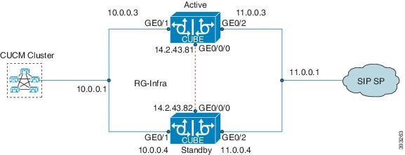


 Feedback