Two Analog Phones
The simplest and most ubiquitous implementation of dial peer configuration involves connecting two standard analog telephones over an IP network. The following two examples illustrate the minimum required configurations necessary to connect two analog phones, where they are attached to the same voice gateway router and where each phone is attached to its own voice gateway router via FXS ports installed in the voice gateway routers in question.
Both Connected to the Same Voice Gateway Router
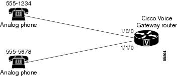
Voice Gateway Router Configuration File
voice-port 1/0/0
!
voice-port 1/0/1
!
!
dial-peer voice 1 pots
 destination-pattern 5551234
 port 1/0/0
!
dial-peer voice 2 pots
 destination-pattern 5555678
 port 1/0/1
Each Connected to Their Own Voice Gateway Routers Using the G.711 Codec

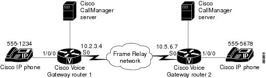
Voice Gateway Router 1 Configuration File
voice-port 1/0/0
!
dial-peer voice 1 pots
 destination-pattern 5551234
 port 1/0/0
!
dial-peer voice 10 voip
 destination-pattern 5555678
 session target ipv4:10.5.6.7
 codec g711ulaw
Voice Gateway Router 2 Configuration File
voice-port 1/0/0
!
dial-peer voice 2 pots
 destination-pattern 5555678
 port 1/0/0
!
dial-peer voice 20 voip
 destination-pattern 5551234
 session target ipv4:10.2.3.4
 codec g711ulaw
Each Connected to Their Own Voice Gateway Routers Using the G.729r8 Codec
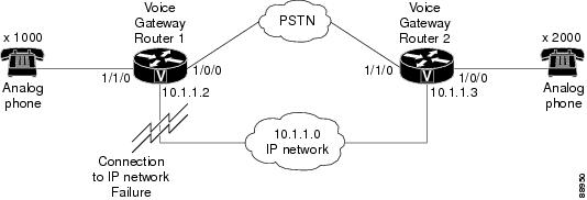
Voice Gateway Router 1 Configuration File
voice class codec 1
 codec preference 1 g729r8
 codec preference 2 g711ulaw
!
voice-port 1/0/0
!
voice-port 1/0/1
!
!
dial-peer voice 1 pots
 destination-pattern 5551234
 port 1/0/0
!
dial-peer voice 2 voip
 destination-pattern 5555678
 voice-class codec 1
 session target ipv4:10.5.6.7
Voice Gateway Router 2 Configuration File
voice class codec 1
 codec preference 1 g729r8
 codec preference 2 g711ulaw
!
voice-port 1/0/0
!
voice-port 1/0/1
!
!
dial-peer voice 1 pots
 destination-pattern 5555678
 port 1/0/0
!
dial-peer voice 2 voip
 destination-pattern 5551234
 voice-class codec 1
 session target ipv4:10.2.3.4


 Feedback