Dial Peer Overview

Configuring dial peers is the key to implementing dial plans and providing voice services over an IP packet network. Dial peers are used to identify call source and destination endpoints and to define the characteristics applied to each call leg in the call connection.

This chapter contains the following sections:

Call Legs

A traditional voice call over the public switched telephone network (PSTN) uses a dedicated 64K circuit end to end. In contrast, a voice call over the packet network is made up of discrete segments or call legs. A call leg is a logical connection between two routers or between a router and a telephony device. A voice call comprises four call legs, two from the perspective of the originating router and two from the perspective of the terminating router, as shown in the figure below.

Figure 1. Dial Peer Call Legs

A dial peer is associated with each call leg. Attributes that are defined in a dial peer and applied to the call leg include the codec, quality of service (QoS), voice activity detection (VAD), and fax rate. To complete a voice call, you must configure a dial peer for each of the four call legs in the call connection.

Depending on the call leg, a call is routed using one of the two types of dial peers:

  • Plain old telephone system (POTS)--Dial peer that defines the characteristics of a traditional telephony network connection. POTS dial peers map a dialed string to a specific voice port on the local router, normally the voice port connecting the router to the local PSTN, PBX, or telephone.

  • Voice-network--Dial peer that defines the characteristics of a packet network connection. Voice-network dial peers map a dialed string to a remote network device, such as the destination router that is connected to the remote telephony device.

Both POTS and voice-network dial peers are needed to establish voice connections over a packet network.

When a voice call comes into the router, the router must match dial peers to route the call. For inbound calls from a POTS interface that are being sent over the packet network, the router matches a POTS dial peer for the inbound call leg and a voice-network dial peer for the outbound call leg. For calls coming into the router from the packet network, the router matches an outbound POTS dial peer to terminate the call and an inbound voice-network dial peer for features such as codec, VAD, and QoS.

The figure below shows the call legs and associated dial peers necessary to complete a voice call.

Figure 2. Matching Call Legs to Dial Peers

The following configurations show an example of a call being made from 4085554000 to 3105551000. The figure below shows the inbound POTS dial peer and the outbound voice over IP (VoIP) dial peer that are configured on the originating router. The POTS dial peer establishes the source of the call (via the calling number or voice port), and the voice-network dial peer establishes the destination by associating the dialed number with the network address of the remote router.

Figure 3. Dial Peers from the Perspective of the Originating Router

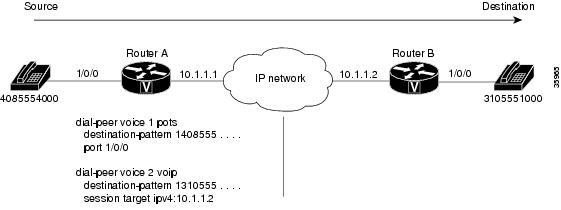
In this example, the dial string 14085554000 maps to telephone number 555-4000, with the digit 1 plus the area code 408 preceding the number. When you configure the destination pattern, set the string to match the local dialing conventions.

The figure below shows the inbound VoIP dial peer and outbound POTS dial peer that are configured on the terminating router to complete the call. Dial peers are of local significance only.

Figure 4. Dial Peers from the Perspective of the Terminating Router

In the previous configuration examples, the last four digits in the VoIP dial peer’s destination pattern were replaced with wildcards. Which means that from Router A, calling any telephone number that begins with the digits "1310555" will result in a connection to Router B. This behavior implies that Router B services all numbers beginning with those digits. From Router B, calling any telephone number that begins with the digits "1408555" will result in a connection to Router A. This behavior implies that Router A services all numbers beginning with those digits.


Note

It is not always necessary to configure the inbound dial peers. If the router is unable to match a configured dial peer for the inbound call leg, it uses an internally defined default POTS or voice-network dial peer to match inbound voice calls. In the example shown in the figure above, dial peer 2 is required only when making a call from Router B to Router A.


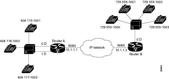
The only exception to the previous example occurs when both POTS dial peers share the same router, as shown in the figure below. In this circumstance, you do not need to configure a voice-network dial peer.

Figure 5. Communication Between Dial Peers Sharing the Same Router

This type of configuration is similar to the configuration used for hairpinning, which occurs when a voice call destined for the packet network is instead routed back over the PSTN because the packet network is unavailable.

POTS Dial Peers

POTS dial peers retain the characteristics of a traditional telephony network connection. POTS dial peers map a dialed string to a specific voice port on the local router, normally the voice port connecting the router to the local PSTN, PBX, or telephone.

Voice-Network Dial Peers

Voice-network dial peers are components on an IP network to which a voice gateway router points via the component’s IP address specified in the session-target command for a particular matching dial peer. The four types of voice-network dial peers (VoIP, voice over ATM (VoATM), voice over Frame Relay (VoFR), and multimedia mail over IP (MMoIP)) are determined according to the given packet network technology and are described as follows:

  • VoIP--Points to the IP address of the destination router that terminates the call.

  • VoFR--Points to the data-link connection identifier (DLCI) of the interface from which the call exits the router.

  • VoATM--Points to the ATM virtual circuit for the interface from which the call exits the router.

  • MMoIP--Points to the e-mail address of the simple mail transfer protocol (SMTP) server. This type of dial peer is used only for fax traffic.

Data Dial Peers

Before Cisco IOS Release 12.2(11)T, a Cisco voice gateway would try to match a voice dial peer before matching and processing a modem call. If a voice dial peer was matched, the call was processed as voice. If there was no voice dial peer match, only then was a call considered to be a modem call. Voice calls always received preference over modem calls. Also, there was no way to assign a subset of addresses in the numbering plan for data calls.

In Cisco IOS Release 12.2(11)T, an interim solution in the form of application called "data_dialpeer" was introduced to enable gateways to identify dial peers. The application enabled the handling of certain matched calls as modem calls. Refer to the Fine-Grain Address Segmentation in Dial Peers feature documentation in Cisco IOS Release 12.2(11)T for more information.

In Cisco IOS Release 12.2(13)T, formal support for data dial peers was released in the form of the Dial-Peer Support for Data Calls feature, which enables the configuration and order assignment of dial peers so that the gateway can identify incoming calls as voice or data (modem). You can use the dial-peer data and dial-peer search commands to perform this configuration. Refer to the "Data Dial Peers" section on page 33 for configuration steps and examples.

Creating a Dial Peer Configuration Table

Before you can configure dial peers, you must obtain specific information about your network. One way to identify this information is to create a dial peer configuration table. This table should contain all the telephone numbers and access codes for each router that is carrying telephone traffic in the network. Because most installations require integrating equipment into an existing voice network, the telephone dial plans are usually preset.

The figure below shows an example of a network in which Router A, with an IP address of 10.1.1.1, connects a small sales branch office to the main office through Router B, with an IP address of 10.1.1.2.


Note

The example in the figure below shows a VoIP configuration. The same concepts also apply to VoFR and VoATM applications. The only change is in the format of the session target.


Figure 6. Sample VoIP Network

Three telephone numbers in the sales branch office need dial peers configured for them. Router B is the primary gateway to the main office; as such, it needs to be connected to the company’s PBX. Four devices need dial peers, all of which are connected to the PBX, configured for them in the main office.

The table below shows the peer configuration table for the example in the figure above.

Table 1. Dial Peer Configuration Table for Sample Voice over IP Network

Dial Peer

Extension

Prefix

Destination Pattern

Type

Voice Port

Session Target

Router A

1

51001

5

1408115....

POTS

0:D

--

2

61002

6

1408116....

POTS

0:D

--

3

71003

7

1408117....

POTS

0:D

--

10

--

--

1729555....

VoIP

--

10.1.1.2

Router B

1

1000, 1001, 1002, 1003

--

1729555....

POTS

0:D

--

10

--

--

1408.......

VoIP

--

10.1.1.1

Codecs

The term codec stands for coder-decoder . A codec is a particular method of transforming analog voice into a digital bit stream (and vice versa) and also refers to the type of compression used. Several different codecs have been developed to perform these functions, and each one is known by the number of the International Telecommunication Union Telecommunication Standardization Sector (ITU-T) standard in which it is defined. For example, two common codecs are the G.711 and the G.729 codecs.

Codecs use different algorithms to encode analog voice into digital bit streams and have different bit rates, frame sizes, and coding delays associated with them. Codecs also differ in the amount of perceived voice quality they achieve. Specialized hardware and software in the digital signal processors (DSPs) perform codec transformation and compression functions, and different DSPs may offer different selections of codecs.

Select the same type of codec at both ends of the call. For instance, if a call was coded with a G.729 codec, it must be decoded with a G.729 codec. Codec choice is configured on dial peers.

The table below lists the H.323, SIP, and MGCP codecs that are supported for voice.

Table 2. Voice Codec/Signaling Support Matrix

Codec

H.323

SIP

MGCP

g711ulaw

Yes

Yes

Yes

g711alaw

Yes

Yes

Yes

g729r81

Yes

Yes

Yes

g729br81

Yes

Yes

Yes

g723ar53

Yes

Yes

Yes

g723ar63

Yes

Yes

Yes

g723r53

Yes

Yes

Yes

g723r63

Yes

Yes

Yes

g726r162

Yes

Yes

Yes

g726r242

Yes

Yes

Yes

g726r32

Yes

Yes

Yes

clear-channel2

Yes

Yes

Yes

iLBC

Yes

Yes

No

1 Annex A is used in the Cisco platforms that are supported in this software release.
2 For dynamic payload types.

For more information, refer to the " Dial Planning " chapter in this document and see the Cisco IOS Voice Port Configuration Guide.

Clear Channel (G.Clear) Codec

G.Clear guarantees bit integrity when transferring a DS-0 through a gateway server, supports the transporting of nonvoice circuit data sessions through a Voice over IP (VoIP) network, and enables the VoIP networks to transport ISDN and switched 56 circuit-switched data calls. With the availability of G.Clear, ISDN data calls that do not require bonding can be supported.

In a transit application, because it is possible to have a mix of voice and data calls, not supporting G.Clear limits the solution to voice-only calls. The end-user application is in charge of handling packet loss and error recovery. This packet loss management precludes the use of clear channel with some applications unless the IP network is carefully engineered.

In an MGCP environment, the voice gateway backhauls the public switched telephony network (PSTN) signaling channel to the call agent. The call agent examines the bearer capability and determines when a G.Clear call should be established.


Note

G.Clear codecs cannot be configured on a T1 channel associated signaling (CAS) trunk for incoming traffic. T1 CAS trunks use least significant bit-robbing for signaling, which causes the data to be incorrect and re-sent from high level protocols. Traffic on an incoming E1 R2 trunk can be configured.


Adaptive Differential PCM Voice Codec G.726

Adaptive differential pulse code modulation (ADPCM) voice codec operates at bit rates of 16, 24, and 32 kbps. ADPCM provides the following functionality:

  • Voice mail recording and playback, which is a requirement for Internet voice mail.

  • Voice transport for cellular, wireless, and cable markets.

  • High voice quality voice transport at 32 kbps.

iLBC Codec

The internet Low Bitrate Codec (iLBC) Has the following benefits:

  • Is designed specifically for packet-based communication.

  • Is royalty free.

  • Provides high-voice quality, even in conditions with high-packet loss.

  • Has a sampling rate of 8 kHz, for narrow band speech.

  • Supports two fixed bit-rate frame lengths:
    • Bit-rate of 13.3 kbps with an encoding frame length of 30 ms
    • Bit-rate of 15.2 kbps with an encoding frame length of 20 ms
  • Is designed to be robust, even with packet loss. iLBC treats each packet independently and recovers from packet loss on the packet immediately following the lost one. By utilizing the entire available frequency band, this codec provides a high voice quality.

Platforms that iLBC Supports

iLBC is supported on Cisco AS5350XM and Cisco AS5400XM Universal Gateways with Voice Feature Cards (VFCs) and IP-to-IP gateways with no transcoding and conferencing.

Using iLBC with SIP

  • For iLBC codecs using SIP, use RFC3952 as a reference for implementation.

  • Mid-call codec parameter changes using SIP are supported. For example, iLBC 'mode' and 'ptime' changes are supported using SIP during the call.

Using iLBC with H.323

  • For iLBC codecs using H.323, a new proposal is written and submitted for approval to ITU. The new proposal is added as 'Annex S' in H245, Version 12 which is used as reference for implementation.

See H245, version 12 document at http://www.packetizer.com/ipmc/h245/

  • Mid-call codec parameter changes using H.323 are not supported.

Toll Fraud Prevention

When a Cisco router platform is installed with a voice-capable Cisco IOS software image, appropriate features must be enabled on the platform to prevent potential toll fraud exploitation by unauthorized users. Deploy these features on all Cisco router Unified Communications applications that process voice calls, such as Cisco Unified Communications Manager Express (CME), Cisco Survivable Remote Site Telephony (SRST), Cisco Unified Border Element (UBE), Cisco IOS-based router and standalone analog and digital PBX and public-switched telephone network (PSTN) gateways, and Cisco contact-center VoiceXML gateways. These features include, but are not limited to, the following:

  • Disable secondary dial tone on voice ports--By default, secondary dial tone is presented on voice ports on Cisco router gateways. Use private line automatic ringdown (PLAR) for foreign exchange office (FXO) ports and direct-inward-dial (DID) for T1/E1 ports to prevent secondary dial tone from being presented to inbound callers.

  • Cisco router access control lists (ACLs)--Define ACLs to allow only explicitly valid sources of calls to the router or gateway, and therefore to prevent unauthorized Session Initiation Protocol (SIP) or H.323 calls from unknown parties to be processed and connected by the router or gateway.

  • Close unused SIP and H.323 ports--If either the SIP or H.323 protocol is not used in your deployment, close the associated protocol ports. If a Cisco voice gateway has dial peers configured to route calls outbound to the PSTN using either time division multiplex (TDM) trunks or IP, close the unused H.323 or SIP ports so that calls from unauthorized endpoints cannot connect calls. If the protocols are used and the ports must remain open, use ACLs to limit access to legitimate sources.

  • Change SIP port 5060--If SIP is actively used, consider changing the port to something other than well-known port 5060.

  • SIP registration--If SIP registration is available on SIP trunks, turn on this feature because it provides an extra level of authentication and validation that only legitimate sources can connect calls. If it is not available, ensure that the appropriate ACLs are in place.

  • SIP Digest Authentication--If the SIP Digest Authentication feature is available for either registrations or invites, turn this feature on because it provides an extra level of authentication and validation that only legitimate sources can connect calls.

  • Explicit incoming and outgoing dial peers--Use explicit dial peers to control the types and parameters of calls allowed by the router, especially in IP-to-IP connections used on CME, SRST, and Cisco UBE. Incoming dial peers offer additional control on the sources of calls, and outgoing dial peers on the destinations. Incoming dial peers are always used for calls. If a dial peer is not explicitly defined, the implicit dial peer 0 is used to allow all calls.

  • Explicit destination patterns--Use dial peers with more granularity than .T for destination patterns to block disallowed off-net call destinations. Use class of restriction (COR) on dial peers with specific destination patterns to allow even more granular control of calls to different destinations on the PSTN.

  • Translation rules--Use translation rules to manipulate dialed digits before calls connect to the PSTN to provide better control over who may dial PSTN destinations. Legitimate users dial an access code and an augmented number for PSTN for certain PSTN (for example, international) locations.

  • Tcl and VoiceXML scripts--Attach a Tcl/VoiceXML script to dial peers to do database lookups or additional off-router authorization checks to allow or deny call flows based on origination or destination numbers. Tcl/VoiceXML scripts can also be used to add a prefix to inbound DID calls. If the prefix plus DID matches internal extensions, then the call is completed. Otherwise, a prompt can be played to the caller that an invalid number has been dialed.

  • Host name validation--Use the "permit hostname" feature to validate initial SIP Invites that contain a fully qualified domain name (FQDN) host name in the Request Uniform Resource Identifier (Request URI) against a configured list of legitimate source hostnames.

  • Dynamic Domain Name Service (DNS)--If you are using DNS as the "session target" on dial peers, the actual IP address destination of call connections can vary from one call to the next. Use voice source groups and ACLs to restrict the valid address ranges expected in DNS responses (which are used subsequently for call setup destinations).

For more configuration guidance, see the Cisco IOS Unified Communications Toll Fraud Prevention paper.