Cisco ONS 15454 and Cisco ONS 15327 TL1 Command Guide, Release 4.6
Bias-Free Language
The documentation set for this product strives to use bias-free language. For the purposes of this documentation set, bias-free is defined as language that does not imply discrimination based on age, disability, gender, racial identity, ethnic identity, sexual orientation, socioeconomic status, and intersectionality. Exceptions may be present in the documentation due to language that is hardcoded in the user interfaces of the product software, language used based on RFP documentation, or language that is used by a referenced third-party product. Learn more about how Cisco is using Inclusive Language.
- Updated:
- March 20, 2015
Chapter: Chapter 5, Ring Provisioning
Ring Provisioning
This chapter provides information and sample procedures for setting up STS or VT circuits over existing path protection and bidirectional line switch ring (BLSR) configurations using TL1, including 1-way drop and continue.

Note ![]() The terms "Unidirectional Path Switched Ring" and "UPSR" may appear in Cisco literature. These terms do not refer to using Cisco ONS 15xxx products in a unidirectional path switched ring configuration. Rather, these terms, as well as "Path Protected Mesh Network" and "PPMN," refer generally to Cisco's path protection feature, which may be used in any topological network configuration. Cisco does not recommend using its path protection feature in any particular topological network configuration.
The terms "Unidirectional Path Switched Ring" and "UPSR" may appear in Cisco literature. These terms do not refer to using Cisco ONS 15xxx products in a unidirectional path switched ring configuration. Rather, these terms, as well as "Path Protected Mesh Network" and "PPMN," refer generally to Cisco's path protection feature, which may be used in any topological network configuration. Cisco does not recommend using its path protection feature in any particular topological network configuration.
Note ![]() Because the ONS 15454/ONS 15327 implements logical path protection, there are no defined east and west ports. Instead, the east STS path for one circuit can exit a different port than the east STS path of another circuit, even though the west STS paths for both circuits may share the same port.
Because the ONS 15454/ONS 15327 implements logical path protection, there are no defined east and west ports. Instead, the east STS path for one circuit can exit a different port than the east STS path of another circuit, even though the west STS paths for both circuits may share the same port.
5.1 1-Way Drop and Continue
The following examples show how to create a 1-way drop and continue cross-connect. The examples use three nodes (Node 1, Node 2, and Node 3) in a ring configuration (Figure 5-1). Node 1 is the source node, Node 2 has the drop and continue, and Node 3 is the destination.
Figure 5-1 1-way drop and continue
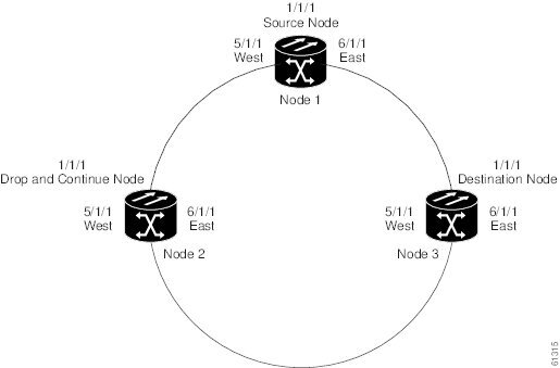
Figure 5-2 shows a circuit diagram example of the orientation of AIDs associated with the ENT-CRS command used to establish drop and continue connections.
Figure 5-2 Orientation of AIDs used to establish drop and continue connections

5.1.1 Sample Node 1 Configuration (Source Node)
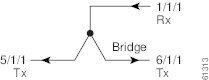
Issue the ENT-CRS-STSn::STS-1-1,STS-5-1&STS-6-1:CTAG::1WAY; command on Node 1.
Figure 5-3 Bridge from 1/1/1 to 5/1/1 and 6/1/1
5.1.2 Sample Node 2 Configuration (Drop and Continue Node)
Issue the ENT-CRS-STSn::STS-5-1&STS-6-1,STS-1-1:CTAG::1WAYDC; on Node 2.
Figure 5-4 Selector between 5/1/1 and 6/1/1 to 1/1/1

5.1.3 Sample Node 3 Configuration (Destination Node)
Issue the ENT-CRS-STSn::STS-5-1&STS-6-1,STS-1-1:CTAG::1WAY; on Node 3.
Figure 5-5 Selector between 5/1/1 and 6/1/1 to 1/1/1
 Feedback