- What’s New in This Chapter
- Core Components
- Key Benefits
- Conference Types
- Architecture
- Role of Cisco Meeting Server
- Role of Cisco TMS
- Role of Cisco TMS Extensions for Microsoft Exchange
- Role of Cisco Meeting Management
- Deployment Overview
- Conference Call Flows
- High Availability for Conferencing
- Security for Conferencing
- Scaling the Conferencing Solution
- Considerations for Multiple Unified CM Clusters
- Conferencing Deployment Process
Conferencing
This chapter describes the components and deployment of video and audio conferencing in an enterprise deployment. The chapter describes the Architecture for conferencing and then outlines the major tasks involved in the Conferencing Deployment Process.
Each major task of the Conferencing Deployment Process starts with an Overview section listing the steps required for that task, followed by a section on the important Deployment Considerations for that task, and then a section (or sections) detailing the deployment tasks listed in the Overview section.
What’s New in This Chapter
Table 3-1 lists the topics that are new in this chapter or that have changed significantly from previous releases of this document.
|
|
|
|
|---|---|---|
Core Components
The core architecture contains these key conferencing elements:
- Cisco Meeting Server for audio and video conferencing as well as conference resource management
- Cisco TelePresence Management Suite (TMS) for conference provisioning, monitoring, and scheduling
- Cisco TelePresence Management Suite Extension for Microsoft Exchange (TMSXE) for interfacing with Microsoft Exchange room and resource calendars
- Cisco Meeting Management for monitoring and managing meetings, as well as provisioning CMS web app users and managing conferencing licenses.
In addition, Cisco TMS architecture includes these non-Cisco components:
Key Benefits
- Simplified and optimized conferencing user experiences with all device types
- Flexible, extendable architecture that supports deployment of one or more permanent, scheduled, and/or instant conference resources
- High availability of conference resources and processes
- Resilience in the video network
- A single tool for hosts to schedule participants and conference rooms for a meeting
- Multiparty licensing enables full access to all conference resources on the bridge
- White glove service to monitor and manage meetings on a single interface
- Browser based application where users can create and participate in meetings
Conference Types
The conferencing solution supports the conference types and conferencing features listed in Table 3-2 .
Architecture
The conferencing architecture consists of Cisco Meeting Server for bridge resources as well as resource management; Cisco TelePresence Management Suite (TMS) for resource provisioning and scheduling; Cisco Meeting Management for conference monitoring and meeting management, conferencing license management, CMS web app user space provisioning; and Cisco Unified Communications Manager (Unified CM) for call processing. SIP call control is used exclusively in this architecture. Use Cisco Meeting Server as the conference bridges for all conference types, and SIP trunks to connect the Cisco Meeting Server with Unified CM (Figure 3-1).
Unified CM communicates with Cisco Meeting Server using XML-RPC over HTTPS to control the conference bridges for instant conferences. Cisco TMS uses the REST API connections to link to the Cisco Meeting Server for provisioning and scheduling conference resources. Cisco Meeting Management and Cisco Meeting Server are connected via REST API, Event subscription, and Call Detail Record (CDR) interfaces to perform meeting management functions. Also, Cisco Meeting Management uses the TMS Booking API to connect with Cisco TMS to manage scheduled meetings. (Figure 3-1)
Figure 3-1 Architecture Overview
For licensing, use and install multiparty licenses along with other feature licenses onto each Cisco Meeting Server. By default, all users in the system use Shared Multiparty plus (SMP+); and if Personal Multiparty plus (PMP+) is desired, PMP+ should be assigned to users via the Cisco Meeting Server API or by provisioning assignment with Cisco Meeting Management. Additional licenses are required for custom layouts and recording and streaming features.
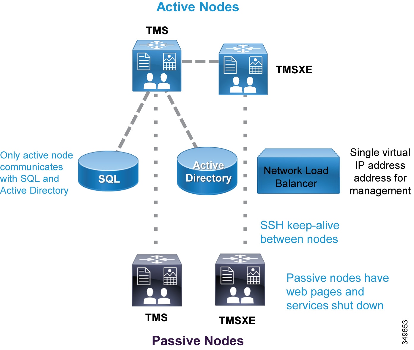
The scheduling architecture consists of an active and a passive node for both Cisco TMS and TMSXE, which are deployed behind a network load balancer. The active node processes the incoming requests, while the passive node runs in standby mode with its web pages and services locked down and refusing all incoming traffic. For large Cisco TMS deployments (see the Sizing chapter), Cisco TMS and TMSXE must be installed on separate virtual machines, as indicated in Figure 3-2. TMS servers are installed in the customer data center that also hosts the organization's SQL deployment. All the server nodes function from an external Microsoft SQL database. Additionally, endpoints, Cisco Meeting Server, and Unified CM are involved in a successful scheduled conference. (Figure 3-2)
Figure 3-2 High-Level View of the Scheduling Architecture
Cisco Meeting Management runs on a separate server outside of Cisco Meeting Server and is dedicated for Cisco Meeting Server deployment only. Cisco Meeting Management users reside in the LDAP directory that it utilizes for user authentication. The users can be assigned as either Cisco Meeting Management Administrators or Operators. LDAP is also leveraged by Cisco Meeting Management to provision Cisco Meeting Server web app users to be able to create their own Spaces using specific templates and permissions. Cisco Meeting Management uses the Event subscription interface and REST API to perform meeting management functions on Cisco Meeting Server. Cisco Meeting Management configures itself as the CDR receiver on Cisco Meeting Server to receive call related events so that it knows when a meeting has started or ended along with other call activities. Cisco Meeting Management uses the TMS Booking API to retrieve information on upcoming scheduled meetings from Cisco TMS. (Figure 3-3)
For compatible versions of Cisco Meeting Server and TMS, refer to the latest version of the Cisco Meeting Management Installation and Configuration Guide, available at
https://www.cisco.com/c/en/us/support/conferencing/meeting-management/products-installation-guides-list.html

Note![]() Cisco Meeting Management requires no extra license other than properly licensed Cisco Meeting Server instance(s).
Cisco Meeting Management requires no extra license other than properly licensed Cisco Meeting Server instance(s).
Figure 3-3 Cisco Meeting Management Architecture

Role of Cisco Meeting Server
Cisco Meeting Server consists of multiple components that provide video conferencing capability (Figure 3-4) and can handle conferences of all types. The Call Bridge component integrates with Unified CM for call control and provides resources to perform conference functions. All Cisco Meeting Server conferences are hosted on CMS Spaces. Spaces are virtual meeting rooms that have audio, video, and content sharing capability and are accessible using the Space URI or directory number. Cisco Meeting Server must integrate with a directory server such as Microsoft Active Directory to import users into the system. During the import process, spaces will be created using the field mapping expressions configuration. All the information for users and Spaces is stored in the database. Participants can join conferences using Cisco or third-party standard video endpoints, Cisco Jabber client, or the browser-based client named CMS web app. The Web Bridge 3 service connects CMS web app users to the Call Bridge and introduces “Call Bridge to Web Bridge” protocol (C2W) to link Call Bridge and Web Bridge 3.
Figure 3-4 Components Inside Cisco Meeting Server

Note![]() Not all Cisco Meeting Server components are shown in Figure 3-4, but only components relevant to the Enterprise Collaboration Preferred Architecture are shown.
Not all Cisco Meeting Server components are shown in Figure 3-4, but only components relevant to the Enterprise Collaboration Preferred Architecture are shown.
CMS web app is a browser-based client that utilizes the WebRTC protocol. With CMS web app, users can log in and join the conference with audio and video along with content sharing. With the CMS web app client, users without an account in Cisco Meeting Server can join the conference as a guest. In addition, users can use CMS web app to run their meetings and perform actions such as view participants, mute and remove participants, start and stop recording, as well as create and edit their own Spaces.
Note![]() CMS web app can be deployed inside or outside of the enterprise network to join a conference, but only deployment inside the enterprise network is covered in this Enterprise Collaboration Preferred Architecture. For deployment outside of the enterprise network, refer to the latest version of the Cisco Meeting Server configuration guides available at https://www.cisco.com/c/en/us/support/conferencing/meeting-server/products-installation-and-configuration-guides-list.html.
CMS web app can be deployed inside or outside of the enterprise network to join a conference, but only deployment inside the enterprise network is covered in this Enterprise Collaboration Preferred Architecture. For deployment outside of the enterprise network, refer to the latest version of the Cisco Meeting Server configuration guides available at https://www.cisco.com/c/en/us/support/conferencing/meeting-server/products-installation-and-configuration-guides-list.html.
Using Cisco Meeting Server for conferences has several benefits, including:
- Scaling easily for small or large deployments, allowing capacity to be added incrementally as needed
- Consistent, intuitive, and optimized conference experiences across all device types
- Unrestricted number of participants in a meeting up to the limit of available underlying hardware when using multiparty licensing
- Single deployment model for all conference types
- A secure collaboration platform using industry standard security architecture and protocols
Role of Cisco TMS
Cisco TMS provides conference scheduling as well as conference room system reservation. Unified CM maintains the configuration control for endpoints, and TMS is then able to push the calendar information to those endpoints. Administrators are able to set the parameters for the default conference for their organization, and then individual conferences will be created according to this template.
Some of the TMS features are not used in the Preferred Architecture – for example, phone books, software management, and reporting functions.
Role of Cisco TMS Extensions for Microsoft Exchange
When end users schedule a meeting in Microsoft Outlook with multiple conference room resources, the Exchange Web Services (EWS) feature of Exchange synchronizes that event into TMS as a scheduled conference. This synchronization is bidirectional, allowing an administrator or support staff to update meetings as well without the need to access the meeting organizer's Outlook event. All endpoint resources within the organization that are intended to be in the conference must be listed on a single Exchange meeting request.
Role of Cisco Meeting Management
Cisco Meeting Management and Cisco TMS work together to provide management and scheduling functions for Cisco Meeting Sever. Cisco Meeting Management provides white glove service for customers, and allows operators to see active meetings, meetings that have ended (up to 7 days), or upcoming scheduled meetings (within the next 24 hours). Operators can view detailed information about meetings, such as participants, meeting duration, and meeting start time. The view on screen for managing meetings can be filtered by activity or status for viewing the relevant display the operator requires.
For active meetings, operators can perform meeting management functions such as:
- Pane placement
- Move or add participants
- Set layout for meeting
- Mute/unmute participants
- Start or stop recording and streaming
- Mute participants
- End the meeting
For individual participants in a meeting operators can:
- View participants call statistics
- Change SIP participants’ layout
- Mute participants audio or video
- Set importance for participant
Users in Cisco Meeting Management belong to one of the user groups, Administrator or Video Operator. Each user group maps to an LDAP group defined inside the directory with users assigned to it. When users log into the portal, Meeting Management authenticates them using the directory and determines their group membership. Administrators have full access to all functions in the Cisco Meeting Management portal. Video Operators only have access to the meeting monitoring and management as well as system status checking functions in the Cisco Meeting Management portal. Local users can also be created for Cisco Meeting Management. Local users can have password policies set as required for security.
Deployment Overview
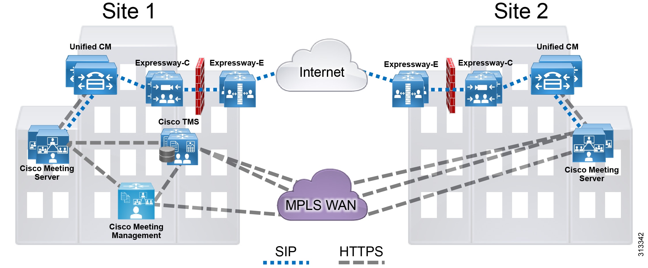
The standard deployment uses multiple Unified CM nodes for call control. Cisco Meeting Server connects to Unified CM with SIP trunks to manage conference resources and to bridge calls. (Figure 3-5) Cisco TMS and Cisco Meeting Management provide conference management facilities and scheduling. In addition to meeting management Cisco Meeting Management manages Cisco Meeting Server licensing and license enforcement. The same conferencing infrastructure is used for both non-scheduled and scheduled conferencing. Cisco Expressway provides the firewall traversal capability to enable business-to-business and mobile and remote access (MRA) calling into the local enterprise. These elements together provide voice and video conferencing for the local enterprise.
Figure 3-5 Standard Deployment

Requirements and Recommendations
- Early Offer messaging is recommended for all SIP trunks connected to Unified CM that carry TelePresence calls.
- Use a single SIP trunk for all conference types (instant, permanent, and scheduled) with a single Cisco Meeting Server.
- Configure Multiparty Licenses in Cisco Meeting Management to host conferences.
- Acquire required certificates for Cisco Meeting Manager as described in the security chapter of this document.
Conference Call Flows
Unified CM provides device registration and routing of voice and video calls between the connected endpoints. Permanent, instant, and scheduled conference calls are all routed over a single SIP trunk to the Call Bridge on Cisco Meeting Server. Each Call Bridge requires a separate SIP trunk. An HTTPS connection is configured on the Unified CM node that carries the XML-RPC requests to the Cisco Meeting Server nodes for instant conferences (see Figure 3-6). When users press the conference softkey on the device to escalate a two-party to three-party call, Unified CM sends an API request to Cisco Meeting Server to create a temporary Space for hosting the conference via this HTTPS connection. Instant, permanent, and scheduled conferences are hosted on Spaces that are created by different components. For more information on Spaces, see section 6. Deploy Cisco Meeting Server Spaces.
Figure 3-6 Unified CM and Cisco Meeting Server SIP Trunk

Instant call flows that are managed by Unified CM cannot be used to add participants to conferences created by any other method, such as scheduled conferences. Other call flows cannot be used to add participants to instant conferences. The instant call escalation method is supported only in an instant conference that was created by it, and conferences generated by other methods cannot be extended by the instant mechanism. This avoids any potential for chained conferences.
Instant Conferences
Instant conferences use an HTTPS XML-RPC connection associated with the SIP trunk between Unified CM and the Call Bridge on Cisco Meeting Server. When a user presses the conference softkey to initiate an instant conference, Unified CM issues an API request through the HTTPS connection to create a temporary Space on Cisco Meeting Server. Unified CM then routes all the participants to that Space through the SIP trunk. When the conference is done, Unified CM issues another API request to delete that Space from Cisco Meeting Server.
Figure 3-7 Instant Conference Call Flow

Permanent Conferences with Cisco Meeting Server Spaces
Permanent conferences are deployed using Cisco Meeting Server spaces. Spaces provide a permanent-type conference and are created as part of the users import process from LDAP either using the Application Programming Interface (API) or Cisco Meeting Management provisioning feature. Users can dial the Space URI at any time to start a meeting. Administrators can specify the Space's attributes (for example: name, username, URIs, and so forth) through the field mappings so that the Spaces can be created using those mappings. Users can then log in using CMS web app client and manage their own Spaces. Connect a SIP trunk between Unified CM and the Call Bridge on Cisco Meeting Server for this conference type. The same SIP trunk is used for other conference types to route conference participants to the Space.
Figure 3-8 Permanent or Scheduled Conference Call Flow
Scheduled Conferences
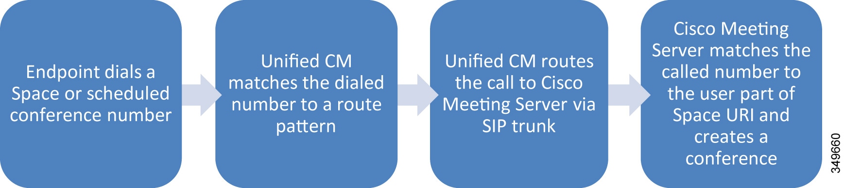
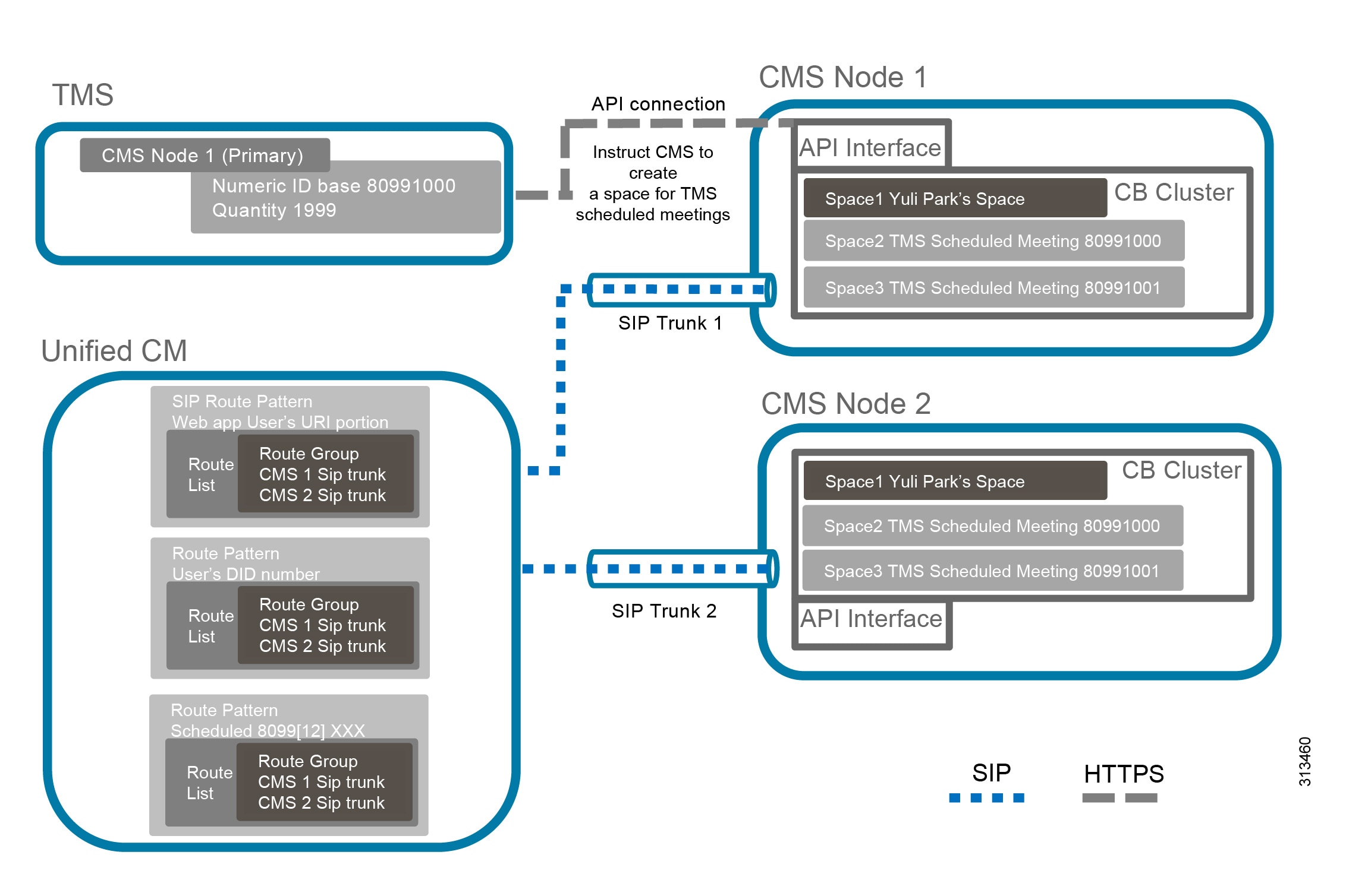
This solution supports scheduling of conferences on Cisco Meeting Server, and scheduling is performed with Cisco TMS. Scheduled conferences require a SIP trunk between Unified CM and the Call Bridge on Cisco Meeting Server. Again the same SIP trunk is used as with other conference types, and Unified CM routes the scheduled conference participants to the destination of the SIP trunk. Add Cisco Meeting Server to Cisco TMS to allow for issuing REST API requests on Cisco Meeting Server through the HTTPS connection. After configuring a range of numeric IDs for scheduled conferences, Cisco TMS creates an inactive Space on Cisco Meeting Server for each numeric ID via the API link. Cisco TMS will then randomly chooses a dial-in number from the range when an organizer schedules a meeting. When it is time to start the scheduled meeting, Cisco TMS activates the Space using the API, and participants can start calling in.
Third-Party Endpoints
Endpoints from other equipment providers can participate in any conferences using standard SIP. Only endpoints registered to Unified CM that support the conference button can initiate an instant conference. Cisco Expressway or Cisco VCS can be used to interwork H.323 calls to SIP, allowing H.323 endpoints to join conferences.
High Availability for Conferencing
High availability must be considered at several levels with the conferencing solution and is achieved in different ways depending on the service being considered.
For both scheduled and non-scheduled conferences, high availability involves Cisco Unified CM, Cisco Meeting Server, and Cisco TMS.
Cisco Meeting Server High Availability
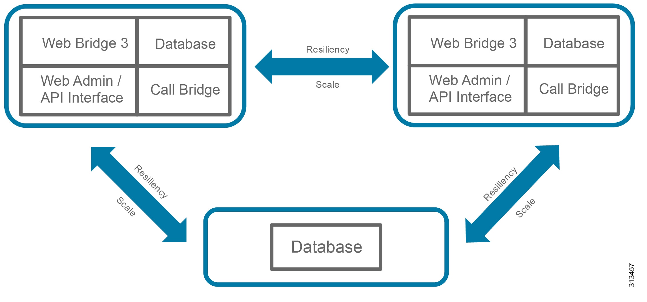
Deploying additional instances of services on one or more servers can provide resiliency for Cisco Meeting Server so that the component instances can share the load, and if one of them fails, the backup instance picks up the load. In addition, Call Bridges and databases can be clustered together to operate as a single instance and Web Bridge 3 instances can be deployed for redundancy. See Figure 3-9.
Figure 3-9 Minimum Components Required for Cisco Meeting Server Cluster with High Availability
Services like Call Bridges and databases can be clustered together to operate as a single instance. Services like a recorder, streamer or Web Bridge 3 have not notion of clustering however, increasing the number of these services across multiple servers will increase the overall capacity of these services. Services like a recorder, streamer or Web Bridge 3 must be configured to work with a specific Call Bridge or Call Bridge group. These services do not interact with non-configured Call Bridges or Call Bridge groups even if they are in the same cluster.
A standard Cisco Meeting Server cluster consists of two or more (up to 24) nodes with Call Bridge service enabled. The maximum round trip time (RTT) between Call Bridges is 300 ms. Call Bridge cluster peers are connected to each other in full mesh via the distribution link. This link is an HTTPS connection used for passing call signaling and control status messages between Call Bridges. Calls can be sent to any Call Bridges in the cluster. If one Call Bridge goes down, Unified CM can route calls to the remaining Call Bridges to join the conferences. In the event that a Call Bridge fails during a live conference, those calls will be dropped and participants will need to dial the same number to join the conference on a new Call Bridge. Using the Unified CM route group and route list construct, calls can be distributed through the SIP trunks to Cisco Meeting Server.
Call Bridges that are configured as a cluster can be put into one or more Call Bridge groups. For Call Bridges within the group, Cisco Meeting Server can intelligently load-balance calls across them and send calls for the same conference to the same Call Bridge whenever possible. When a call is sent to a Call Bridge, Cisco Meeting Server decides to reject or accept the call based on the current load in the Call Bridge. If the current load is less than the preset threshold, the call will be accepted. Otherwise, the call will be rejected and Unified CM will reroute the call to another Call Bridge in the Call Bridge group using the dial plan configuration. If Unified CM cannot find any Call Bridge that accepts the call, the whole call will be rejected. After a Cisco Meeting Server accepts the call, the call could be hosted on the Call Bridge of this Cisco Meeting Server or moved to another Call Bridge with highest priority according to an internal ordered list for the conference. When the call is moved, the target Cisco Meeting Server with the Call Bridge enabled sends an INVITE with Replaces to Unified CM to take over the call. By default, a Call Bridge in a Call Bridge group will reject all calls for new participants at 80% load, and only new distribution calls will be allowed. For network requirements between Call Bridges, RTT should be 100 ms or less between Call Bridges inside the group and 300 ms or less between any two Call Bridges in the same cluster. Call Bridge groups are supported with both Unified CM as well as Cisco Expressway using the same load balancing logic. Table 3-3 shows the maximum RTT allowed between the service components.
|
|
|
|---|---|
Note![]() If Call Bridge groups and load balancing are not used, then calls will not be rejected, but the quality of all calls will be reduced when the load limit is reached. If this happens often, we recommend deploying additional hardware. A review by Cisco engineering is required in designs that require eight or more servers. To engage engineering email them at personalmultiparty@cisco.com.
If Call Bridge groups and load balancing are not used, then calls will not be rejected, but the quality of all calls will be reduced when the load limit is reached. If this happens often, we recommend deploying additional hardware. A review by Cisco engineering is required in designs that require eight or more servers. To engage engineering email them at personalmultiparty@cisco.com.
Note![]() For more information on load balancing calls across meeting servers see Cisco Meeting Server 3.2, White Paper on Load Balancing Calls Across Cisco Meeting Servers located here: https://www.cisco.com/c/en/us/support/conferencing/meeting-server/products-installation-and-configuration-guides-list.html
For more information on load balancing calls across meeting servers see Cisco Meeting Server 3.2, White Paper on Load Balancing Calls Across Cisco Meeting Servers located here: https://www.cisco.com/c/en/us/support/conferencing/meeting-server/products-installation-and-configuration-guides-list.html
The database cluster consists of one master and multiple replicas, up to a maximum of 5 nodes with maximum RTT of 200 ms between databases. The database master can perform both read and write operations, while replicas can only have read access. Call Bridges always connect to the database master for read and write, and all changes made on the master are replicated to the replicas. Call Bridges with a local database automatically connect to the master of the local database cluster, while Call Bridges with no local database have to be connected manually to the database cluster. If the master fails, one of the replicas will become the new master, and other replicas will re-register with this new master. After correcting the failure, the old master will become the replica and register with the new master. In cases where a network partition occurs, only database nodes that can see more than half of the cluster members are considered for promotion to become a master. Likewise, any existing master that cannot see more than half of the cluster members will be demoted to a replica. This ensures that multiple masters are not created. So, if a database cluster consists of an even number (2 or 4) of nodes and the network is partitioned into 2 segments with an equal number of nodes are on each side, the master on one side will be demoted to a replica since it cannot see more than half of the cluster members. In that case, there will be no master in the cluster, and the Call Bridges can still take calls but no database write operations are possible. For this reason, we recommend having an odd number of nodes in the database cluster to ensure that a master is always elected. As a result, the minimum number of database nodes in a cluster is 3.
Call Bridge clusters provide failover protection for a CMS web app client by having more than one Web Bridge 3 instance added. All nodes in a Call Bridge cluster should be able to reach out to a C2W instance for the web bridge3 service to be available for authenticated users and guests. If a Call Bridge cannot establish a TLS connection to the C2W the web bridge3 service shows up as unavailable.
Web bridge3 instances are not aware of the existence/location of the other Web bridge3 instances. The web bridge3 services can be reached by the CMS web app clients via a single DNS A record. To instruct Call Bridges on how to reach the Web Bridge 3, a Web Bridge 3 object is created and a c2w://url is specified. The c2w://url must have a unique hostname/A record to reach each Web Bridge 3 at the interface where the C2W is listening, in this way each Web Bridge 3 can identify the unique specific Call Bridge connection and peer id.
Every Call Bridge in the cluster will continuously communicate with every Web Bridge 3 via C2W interface, unless Call Bridge groups are configured. In Call Bridge groups every Call Bridge will communicate with the Web Bridge 3 instance assigned to the group.
When a guest or authenticated user joins the Web Bridge 3, one of the Call Bridges that are alive connecting via C2W interface will be selected. Call Bridge will reach c2w://url and it will validate that the A record of the URL is present in the as a Subject Alternative Name or Common Name in the certificate presented by the C2W instance. If the validation fails Call Bridge web user interface will show a TLS negotiation error towards the c2w://url. Web Bridge 3 also validates that the certificate presented by the Call Bridge is trusted by the C2W trust store.
Figure 3-10 illustrates the application flow of Web Bridge 3 at a high level.
Figure 3-10 Web Bridge 3: High level application flow

Referring back to Figure 3-9 illustrating the minimum components required for CMS with high-availability. Enable at least 2 instances of each component service (Web Bridge 3 and Call Bridge) in separate servers, and put the Call Bridges into a group. There is no need to activate all services inside each server; activate only the ones that are required. If the deployment requires more capacity than the 2 Call Bridges can handle, additional Call Bridge can be set up in the third server (no need to acquire a fourth server for just the Call Bridge). Table 3-4 lists the minimum Cisco Meeting Server cluster configuration required for various numbers of Call Bridges for a single Unified CM cluster.
TMS High Availability
High availability of a large Cisco TMS deployment includes: Two TMS front-end servers, two servers running TMSXE, a network load balancer, and an external Microsoft SQL database (see Figure 3-2). TMS resiliency supports only two servers – one active node and one passive node – and this model does not increase or decrease the capacity of the TMS deployment. The network load balancer (NLB) is deployed in front of the TMS servers. Inbound traffic to TMS goes through the NLB, which forwards it to the active node. Outbound traffic from TMS is sent directly to the destination without going through the NLB. If the NLB detects a failure on the existing active node, it automatically switches to the new active node without any user intervention.
Cisco Meeting Management High Availability
Cisco Meeting Management does not have the built-in cluster function for resiliency. For high availability, customers can configure two Cisco Meeting Management instances to manage the same Cisco Meeting Server deployment. Each Cisco Meeting Management instance is configured independently and gets data from the connected Cisco Meeting Servers and Cisco TMS. No information is exchanged between the Cisco Meeting Management instances, nor is there failover when a server fails, as such there is no benefit to deploying a load balancer. Cisco Meeting Management users are directed to the address of the appropriate Cisco Meeting Management instance to manage conferences. In the event of a failure with the Cisco Management in use, users are asked to sign in to the other Cisco Meeting Management server while corrective action is taken to resolve issue with original Cisco Meeting Management.
Security for Conferencing
The Preferred Architecture fully supports media and signaling encryption; but for simplicity, the solution presented in this document implements non-secure SIP trunks between Unified CM and Cisco Meeting Server for all conferences. An exception to this is the solution requirement that API communications between unified CM and the Cisco Meeting Server must be encrypted.
Cisco Meeting Server uses secure connections to communicate with external components as well as between internal components, and certificates are required. Use certificate authority (CA) signed certificates to secure the connections between components. Refer to the Security chapter for further detail.
Another level of security can be added to restrict access to the conferences themselves with PINs or passwords. Any scheduled conference or permanent conference can have a PIN set so that all participants are challenged to enter the PIN before being allowed to connect.
Scaling the Conferencing Solution
You can scale the conferencing solution primarily by adding more Call Bridges (up to 24) to a standard Cisco Meeting Server cluster.
In this deployment, based on the dial plan and route group and route list configuration with the SIP trunks in Unified CM, calls can be routed to any Call Bridge within the cluster. If calls for the same conference are routed to different Call Bridges, the audio and video of the last 4 active speakers are exchanged between Call Bridges for participants on one bridge to see the active speakers on the other bridge.
Note![]() Cisco Meeting Server supports clustering with more than 8 Call Bridges, but deployment requires prior approval by Cisco. Contact your local Cisco account team for details.
Cisco Meeting Server supports clustering with more than 8 Call Bridges, but deployment requires prior approval by Cisco. Contact your local Cisco account team for details.
Each Call Bridge can support 450 participants. Thus, the maximum number of participants per conference is 450 with a single server, and up to 2,600 participants across multiple servers in a single cluster.
Considerations for Multiple Unified CM Clusters
For large-scale deployments with multiple Unified CM clusters, use a single Cisco Meeting Server cluster configured with multiple Call Bridge groups, and dedicate one group to each Unified CM cluster.
For example, if your deployment has three Unified CM clusters, then you should deploy a single Cisco Meeting Server cluster with three Call Bridge groups, one in each Unified CM cluster. Each Unified CM cluster should have a SIP trunk to each Call Bridge in its local Call Bridge group. All incoming conference calls to a Unified CM cluster will be handled by the local Call Bridge group. Call Bridges should have their distribution links connected to their peers inside and outside of the groups in full mesh. For the same conference, users can dial in from their Unified CM cluster to reach the local Call Bridge group, and the Call Bridges in different groups will exchange the audio and video of the last 4 active speakers with their peers so that participants can see each other across the bridges. (Figure 3-11)
Figure 3-11 Cisco Meeting Server Deployment with Multiple Unified CM Clusters

For the first Unified CM cluster, refer to the section on Cisco Meeting Server High Availability and Table 3-4 for the design.
For the second Unified CM cluster, expand the Cisco Meeting Server cluster to add 2 extra servers. In each of the servers, enable the web bridge and Call Bridge. No extra database are required for this Unified CM cluster. Connect the Call Bridges to the existing database cluster. Put the Call Bridges into a new Call Bridge group that is used by this second Unified CM cluster, and associate the web bridges with this Call Bridge group. If additional capacity is desired, add an extra server to host a Call Bridge, and put that Call Bridge into the Call Bridge group for this second Unified CM cluster. Table 3-5 illustrates the additional Cisco Meeting Server cluster configuration required for the second Unified CM cluster, based upon the number of additional Call Bridges required.
For the third Unified CM cluster, expand the Cisco Meeting Server cluster to have 2 extra servers. In each of the servers, enable the Web Bridge 3 and Call Bridge. Connect the Call Bridges to the existing database cluster, and add all additional Call Bridges. Put the Call Bridges into a new Call Bridge group that is used by this third Unified CM cluster, and associate the web bridges with this Call Bridge group. If additional capacity is desired, add an extra server to host a Call Bridge, and put that Call Bridge into the Call Bridge group for this third Unified CM cluster. Table 3-6 illustrates the additional Cisco Meeting Server node configuration required for the third Unified CM cluster, based upon the number of additional Call Bridges required.
With three Unified CM clusters and thus three separate Call Bridge groups, the database cluster nodes local to the first Call Bridge group can be distributed among the Call Bridge groups so that each Call Bridge group would have a local XMPP and database cluster node. By migrating two database cluster nodes local to the first Call Bridge group to the second and third Call Bridge groups, respectively, this creates redundancy for the database services across each Call Bridge group. Table 3-7 illustrates this new Cisco Meeting Server cluster configuration.
|
|
|
|---|---|
If the deployment requires a fourth Unified CM cluster, we recommend moving to a Cisco Unified CM Session Management Edition design, which is out of the scope for this document.
The following guidelines apply when expanding the Cisco Meeting Server cluster into different regions for multiple Unified CM clusters:
- A single Cisco Meeting Server cluster should be used for deployment of one or more Unified CM clusters.
- You may deploy up to 8 Call Bridges for the standard Cisco Meeting Server cluster. If the cluster exceeds 8 Call Bridges, acquire Cisco account team approval before deployment.
- Deploy a maximum of 5 databases and an odd number of nodes in the Cisco Meeting Server cluster.
- Round-trip-time (RTT) network requirements:
–![]() Maximum of 300 ms between Call Bridges and 200 ms between databases in the Cisco Meeting Server cluster
Maximum of 300 ms between Call Bridges and 200 ms between databases in the Cisco Meeting Server cluster
Conferencing Deployment Process
To deploy the conferencing solution, perform the following major tasks in the order listed here:
1. Plan the Conferencing Deployment
2. Deploy Cisco Meeting Servers
3. Enable Unified CM for Conferences
5. Deploy Cisco TelePresence Management Suite
6. Deploy Cisco Meeting Server Spaces
7. Deploy Cisco Meeting Management
1. Plan the Conferencing Deployment
Before deploying the conferencing solution, plan for the following aspects:
Requirements
- Configure DNS for Cisco Meeting Server, which needs a number of DNS SRV and A records. For example, Cisco Meeting App uses the _xmpp-client SRV record to look up the XMPP service for user authentication.
- Cisco Meeting Server requires the use of an API client to complete the deployment. Acquire a tool that can be used to issue REST API commands for an update; for example, Postman ( https://www.getpostman.com/) or use the API navigator within CMS web user interface under Configuration > API.
- Refer to the Security chapter of this document for certificate requirements. Information for these requirements can also be found at https://www.cisco.com/c/en/us/support/conferencing/meeting-server/products-installation-and-configuration-guides-list.html
Licensing
Licenses must be installed on various products:
- Cisco TMS must have enough device licenses installed for the deployment.
- Cisco Meeting Server must have enough Multiparty licenses installed on each node running the Call Bridge or enough Multiparty licenses available in the smart account if using Smart Licensing option with Cisco Meeting Management.
- Cisco Meeting Server optional features require an additional license. These features are:
Cisco Meeting Management is required with Cisco Meeting Server for license reporting and integration with Cisco Smart Licensing for license management.
Multiparty is a user-based licensing model recommended for Cisco Meeting Server deployment, and it should be applied to every node with Call Bridge service enabled. It comes with two variations: Personal and Shared. Personal Multiparty Plus (PMP+) is for specific named hosts while Shared Multiparty Plus (SMP+) is for conference room systems or for sharing between users. Each license entitles a user to host a conference with unlimited participants and up to 1080p video resolution. Table 3-8 summarizes the features included in the Personal and Shared Multiparty licenses.
|
|
|
|
|---|---|---|
| Personal and scheduled meetings for all users, unrestricted meeting size, floating licenses |
||
Multiparty licensing is the license model used in the Preferred Architecture.
Cisco TelePresence Management Suite
Before beginning the installation and configuration process, you must decide on several items to align with the specific structure and preferences of your organization. Some specific settings must be used during the configuration process and should be gathered prior to beginning the install process.
Microsoft SQL
Cisco TMS utilizes an external Microsoft SQL database to store all data regarding meetings, users, and systems. During the installation process, TMS and associated software extensions create a number of specific databases. The TMS application does not allow users to log into the web page if communication is not currently active with the tmsng database. This dependency on constant communication with the SQL database requires the SQL database to utilize Microsoft's methods for making the database resilient as well. The databases will vary in size depending upon the deployment size and number of scheduling events; but as a general guideline, 1 GB of initial storage will suffice for most organizations.
Table 3-9 lists the Microsoft SQL specifics required to support Cisco TMS.
|
|
|
|---|---|
AlwaysOn Failover Cluster instances through Windows Server Failover Clusters (WSFC) |
Note![]() While other modes of SQL resiliency are supported by TMS, any method besides AlwaysOn Failover Cluster requires manual adjustments by the TMS administrator during an SQL outage situation.
While other modes of SQL resiliency are supported by TMS, any method besides AlwaysOn Failover Cluster requires manual adjustments by the TMS administrator during an SQL outage situation.
Active Directory
Cisco TMS integrates with many aspects of Microsoft Active Directory, and the server must be added to the organization's domain,. All TMS users must be imported from and authenticated with Active Directory.
During the configuration process, you must enter an AD Service account username and password for TMS to import users. This is a read-only account, and TMS does not modify any information in Active Directory. This account should have access to the highest level of the AD structure that enables all subsequent end users to access its functionality. In organizations with multiple domains, the TMS user account must be associated with the top level domain. An additional service account is required for the TMSXE application for end-user booking of Exchange resources. This should also be a read-only service account, and end user credentials are used for the actual event booking. TMSXE user account permits only the TMSXE application to authenticate and communicate with the Exchange Servers through Exchange Web Services.
Additionally, identify existing, or create new, Groups with AD that will serve to synchronize TMS administrators and end users with scheduling access to TMS.
Note![]() Local machine accounts on the TMS server should not be used because they are not duplicated between front-end servers, and the user credentials would not be available if the other node became active.
Local machine accounts on the TMS server should not be used because they are not duplicated between front-end servers, and the user credentials would not be available if the other node became active.
Email Integration
TMS sends automated emails to users when they schedule meetings, with all connection information included for the participants. During the installation process, you must enter the "from" address that end users will see as the originating for these emails, so select an address such as collabconferencing@ent-pa.com or a similar address not currently used in your organization.
You will also need to enter the SMTP address of the outgoing mail server.
Endpoint Naming Conventions
Endpoints are added to Cisco TMS for two reasons:
- Correlation with Exchange resources for conference resource allocation
- Enabling TMS to provide One Button to Push connection information on the endpoint user interface
As endpoints are added to TMS, use the same character string as the room or resource name in Exchange. This provides uniformity and consistency to end users when system names appear in the call history and fill the text of on-screen labels from conferencing resources.
An organized plan for how to use the folder structure of TMS Systems Navigator will also assist the administrator in having a simplified interface.
Default Conference Parameters for Your Organization
These settings are customizable for each organization and should be used in accordance with your own network considerations, meeting flows, and corporate culture. The default conference settings are used for all meetings scheduled by end users through Outlook. For all possible settings of the default conference, refer to the latest version of the Cisco TelePresence Management Suite Administrator Guide, available at
https://www.cisco.com/c/en/us/support/conferencing/telepresence-management-suite-tms/products-maintenance-guides-list.html
Cisco Meeting Server Space Provisioning
An understanding of how the organization plans to utilize Cisco Meeting Server Spaces requires an understanding of the workflow that end users expect for meetings. Some organizations may choose to leverage the Spaces instead of scheduled resources for certain meeting types, especially in cases where workers are in separate locations and not able to gather in a common conference room.
Location of Servers
Both the active and passive nodes for a redundant TMS deployment must be configured with the same time zone within the server operating system. In addition, this must be the same time zone as the SQL server. Support of TMS redundancy is limited to the same local network for both the active and passive nodes, along with the SQL server.
2. Deploy Cisco Meeting Servers
This section describes the major tasks required to deploy Cisco Meeting Servers and prepare them for use with scheduled and non-scheduled conferences.
Overview
| Deployment Tasks for Cisco Meeting Servers: 1. 2. 3. 4. 5. 6. 7. 8. |
Deployment Considerations
The physical location of a Cisco Meeting Server is important to consider because media traffic flows between it and each participant in the conference. To provide the best experience for participants, centralize the location of the Cisco Meeting Server with Call Bridges and put them into a group for each regional Unified CM cluster.
If the deployment includes CMS Web app or a Web Bridge 3 avoid using the parent domain (for example, ent-pa.com) as the user domain video domain because other components such as Cisco Unified CM IM and Presence Service might have already used it, which could complicate the overall design. We recommend using a sub-domain such as cms.ent-pa.com to create a concise dial plan.
Deploy a 3-node cluster for database; this should cover a majority of deployment scenarios to provide resiliency and high availability.
Create a DNS A record using the same name (for example, join.ent-pa.com) to point to each Web Bridge 3 so it is easy for participants to remember the web bridge URL (from example, https://join.ent-pa.com) used to join the conference and could load balance the CMS Web app connections using a load balancing method.
Deployment Tasks for Cisco Meeting Servers
Cisco Meeting Server cannot take calls without a Call Bridge license. The Call Bridge, multiparty license along with other feature licenses are managed by Cisco Meeting Management and is described in the Cisco Meeting Management section of this chapter.
Go to the Cisco Meeting Server section of the Security chapter for details on how to generate the enterprise CA signed certificates. This will generate 2 certificates; one certificate that is shared for web admin, Call Bridge, Web Bridge 3, and database cluster and the database client certificate which is used for database cluster internal communication.
Web Bridge 3 (skip if this is not a Call Bridge node):
For web admin, use the Mainboard Management Processor (MMP) commands to specify the listening interface and port, install the shared CA signed certificate, and enable the service. This allows the administrator to access the Web interface using the specified listening interface and port. By default, both web admin and web bridge use TCP port 443. If they both use TCP port 443, then they need to use different network interfaces. However, if the same interface is used, one of the services must have a different default port. In that case, we recommend changing the web admin default port to some other used port (for example, TCP port 444).
For the Call Bridge, use MMP commands to specify the listening interface, install the shared CA signed certificate, and restart the service.
Steps to configure the Web Bridge 3 (skip if this is not a Call Bridge node):
1.![]() For Web Bridge 3, use MMP comands to specify the listening interface, commands uses are found in the Security chapter.
For Web Bridge 3, use MMP comands to specify the listening interface, commands uses are found in the Security chapter.
2.![]() Install the full chain certificate which is in the shared certificate and the complete trust chain. The entity must be on the top, then the intermediate chains if applicable and end with the root CA chain.
Install the full chain certificate which is in the shared certificate and the complete trust chain. The entity must be on the top, then the intermediate chains if applicable and end with the root CA chain.
3.![]() Specify the C2W port, it should be a TCP port different than the Web Bridge 3 listening port and web admin listening port if it is running on the same server.
Specify the C2W port, it should be a TCP port different than the Web Bridge 3 listening port and web admin listening port if it is running on the same server.
4.![]() Configure the shared certificate and the complete trust chain that C2W will send to the Call Bridge.
Configure the shared certificate and the complete trust chain that C2W will send to the Call Bridge.
5.![]() Configure the Root Certificate Authority chain in the C2W trust store to validate Call Bridge certificate.
Configure the Root Certificate Authority chain in the C2W trust store to validate Call Bridge certificate.
6.![]() Create a Web Bridge 3 object in Cisco Meeting Server to configure the c2w url.
Create a Web Bridge 3 object in Cisco Meeting Server to configure the c2w url.
7.![]() Navigate to the web admin interface of the Cisco Meeting Server and navigate to Configuration > API. Use the filter field to find object “/api/v1/webBridges” and expand the list.
Navigate to the web admin interface of the Cisco Meeting Server and navigate to Configuration > API. Use the filter field to find object “/api/v1/webBridges” and expand the list.
8.![]() Click on “create new” and enter the c2w “url: c2w://us-cms-1.ent-pa.com:9999” and click on “create”.
Click on “create new” and enter the c2w “url: c2w://us-cms-1.ent-pa.com:9999” and click on “create”.
9.![]() The web bridge 3 connects to the call bridge after accepting the connection from the CMS Web app client, and therefore it needs to trust the certificate from call bridge.
The web bridge 3 connects to the call bridge after accepting the connection from the CMS Web app client, and therefore it needs to trust the certificate from call bridge.
Repeat the steps above for every node in the cluster hosting a Web Bridge 3 instance
Set up the database cluster
On each database node, use the MMP commands to specify the network interface used by the database, and install the shared CA signed certificate. Select one node as the master and run the MMP command to initialize the database. Go to each database replica node, and run the MMP command to join the database with the cluster. On all nodes that have the Call Bridge without a local database, install the second certificate and run the MMP command to connect to the cluster. Ensure that the command execution status is successful before moving on to the next command. This completes the database cluster setup.

Warning![]() Data in the replica database will be overwritten by the master after the replica joins the cluster.
Data in the replica database will be overwritten by the master after the replica joins the cluster.
Setup the Call Bridge cluster.
On each Call Bridge node, go to the web interface (Configuration -> Cluster) and configure a Unique name (for example, callbridge1) under Call Bridge identity for the Call Bridge. After that, go back to the cluster configuration (Configuration -> Cluster) on one of the Call Bridge nodes, fill in the Clustered Call Bridges with the information for all Call Bridges, using the sample in Table 3-10 , and leave other fields blank or as default:
|
|
|
|
|---|---|---|
| Address column is the URL and port number used to access the web interface |
||
The Clustered Call Bridges configuration will appear in all Call Bridge nodes from the web interface. These are the distribution links used by the Call Bridges to pass call signal and status messages between peers for distributed conferences.
Each Call Bridge should have an outbound dial plan rule configured for each of its peers so that it routes calls directly to its peer instead of through a call control. Configure an outbound rule to each of the peers based on the ip addresses of the peers as show in Table 3-11 .
|
|
|
|
|
|
|---|---|---|---|---|
For each Web Bridge 3 deployed, the Call Bridge needs to know the c2w://URL for accessing the Web Bridge 3. Run the POST method on the /webBridges node using the URL parameter from each row in Table 3-12 .
|
|
|
|---|---|
Using the same name (for example, join.ent-pa.com) for each web bridge, create a DNS A record that resolves to the IP address of the interface used by the web bridge.
Use an API (POST /callBridgeGroups) with the parameter loadBalancingEnabled set to true to create a Call Bridge group with the load balancing option enabled, and write down the returned Call Bridge group GUID. For each Call Bridge, use an API (PUT /callBridges) to set the callBridgeGroup parameter to the <callBridgeGroup GUID> for adding the Call Bridge to the group. Use an API (PUT /system/configuration/cluster) to set the loadLimit parameter value for the maximum load on the server platform, using the platform dependent value as specified in the latest version of the white paper on Load Balancing Calls Across Cisco Meeting Servers, available at,
https://www.cisco.com/c/en/us/support/conferencing/meeting-server/products-installation-and-configuration-guides-list.html
For each web bridge, use an API (PUT /webBridges) to set the callBridgeGroup parameter to the <callBridgeGroup GUID> to associate the web bridge with the Call Bridge group so that only Call Bridges in the group will attempt to connect to the web bridge.
At this point, a complete Cisco Meeting Server cluster should be configured. Browse to one of the web admin pages and update the call settings parameters in the web interface (Configuration -> General) using the values in Table 3-13 .
|
|
|
|
|---|---|---|
Summary
After completing the above tasks, the Cisco Meeting Servers will be ready to add to Unified CM.
3. Enable Unified CM for Conferences
This section describes the major tasks required to enable Unified CM for conferences with the Cisco Meeting Server cluster.
Overview
| Deployment Tasks to Enable Unified CM for Instant Conferences: 1. 2. 3. Configure each conference bridge with the username and password created on Cisco Meeting Server with API privilege. This step must be repeated for each Call Bridge enabled in the Cisco Meeting Server cluster. For example, if there are three Call Bridges in the cluster, there should be three conference bridges configured. 4. 5. |
| Deployment Tasks to Enable Unified CM for Permanent and Scheduled Conferences: 6. 7. 8. |
Deployment Considerations
Unified CM is the first point of logic that decides how to route a call to Cisco Meeting Server to start the conference. Unified CM has different configuration procedures for instant and permanent or scheduled conferences because the mechanism for joining each type of conference is different.
Note![]() The endpoint used to initiate an instant conference must have a conference button. Endpoints that do not have a conference button can still be participants in an instant conference, but they must be added to the conference by an endpoint that has a conference button.
The endpoint used to initiate an instant conference must have a conference button. Endpoints that do not have a conference button can still be participants in an instant conference, but they must be added to the conference by an endpoint that has a conference button.
Deployment Tasks to Enable Unified CM for Instant Conferences
It is important to understand that the SIP trunk in Unified CM should point to the call bridge in the Cisco Meeting Server, while the API connection should point to the web admin interface and port. The API connection must be secured using HTTPS hence Unified CM should trust the certificate presented by the Web admin, in this case the shared certificate. Upload the root certificate of the Certificate Authority that signed the shared certificate into the Tomcat Trust store before adding Cisco Meeting Server as Conference Bridge (CFB). The same SIP trunk can be used for all conference types. Each call bridge node within the Cisco Meeting Server cluster requires a unique set consisting of a SIP trunk and an API connection from the conference bridge in Unified CM.
SIP trunks to Cisco Meeting Server require a customized SIP profile and SIP trunk security profile in order to support calls in all scenarios. To create the SIP profile, copy the Standard SIP Profile for TelePresence Conferencing and name the copy Standard SIP Profile for CMS, then change the settings as indicated in Table 3-14 .
To create the SIP trunk security profile, copy the Non Secure SIP Trunk Profile and name the copy Security SIP Trunk Profile for CMS, then change the settings as indicated in Table 3-15 .
SIP trunks inform Unified CM where to route SIP traffic. In the case of instant conferences, Unified CM will use the destination ip of the trunk to send the direct API requests, and they are used in the conference bridge configuration (Figure 3-12). SIP trunks connected to the Call Bridge in Cisco Meeting Server can be configured to be secure; but for the purpose of this guide, they are assumed to be configured as non-secure.
Figure 3-12 Cisco Unified CM Instant Configuration

Conference bridge configuration provides two key pieces of information to Unified CM: the API credentials to communicate with Cisco Meeting Server and the destination address for that communication (Figure 3-12). The username and password should match those for the API user configured in Cisco Meeting Server. Unified CM should trust the Certificate Authority that signed the shared certificate, make sure that the root CA certificate exists in the tomcat trust store of Unified CM. The SIP trunk configured in the conference bridge indicates to Unified CM where to send the HTTPS API traffic. Configure each SIP trunk with the settings indicated in Table 3-16 . In addition, each Unified CM cluster should have a unique Conference Bridge Prefix configured in the conference bridges. The prefix does not affect operations in a single Unified CM cluster; but in multi-cluster Unified CM deployments, this prefix would prevent two Unified CM clusters from assigning the same meeting number to different instant conferences at the same time.
|
|
|
|
|---|---|---|
Name of the SIP trunk pointing to Cisco Meeting Server node 1 with the Call Bridge enabled |
||
This will allow the ASCII Alerting Name to be transmitted to devices that support UTF-8 characters |
||
This setting is recommended on all SIP trunks. It makes sure that outbound calls to SIP do not require intra-cluster control signaling between Unified CM call processing subscribers. |
||
|
|
||
As defined in the Call Control chapter |
||
|
|
||
|
|
||
Use the same Calling Search Space as configured for Inbound Calls above. |
||
Once all conference bridges are configured, they can be added to media resource groups (MRG). Each media resource group should contain one conference bridge from each Call Bridge in the Cisco Meeting Server node, so that if communication with one Call Bridge node is not possible, then calls can be routed to another node.
Each media resource group can then be added to its own media resource group list (MRGL). The media resource group list can be assigned to devices or the device pool in Unified CM and used when those devices escalate a point-to-point call to a conference call using the conference button.
Inside Cisco Meeting Server, the Space used by the instant conference is created dynamically through the HTTPS API connection when a user presses the conference button on the device to initiate the escalation. That Space will be deleted through the API connection after the conference ends.
Deployment Tasks to Enable Unified CM for Permanent and Scheduled Conferences
Permanent and scheduled conferences are configured on Unified CM in a similar way to instant conferences, but they require a dial plan to be configured rather than media resources (see Figure 3-13). Use the same SIP trunk and SIP profile for permanent and scheduled conferences that you created for instant conferences, with the settings indicated in Table 3-16 .
Figure 3-13 Scheduled and Permanent conferences dial plan for Cisco Unified CM and Cisco Meeting Server Spaces
Create a route group for all the SIP trunks created for scheduled conferences. Add the route group into a route list. The route list is chosen when a call matches a route pattern that points to it.
To route calls through the SIP trunk to the Cisco Meeting Server, configure a route pattern for the route list. The route pattern should match with the alias range configured for the scheduled conferences, as indicated in Table 3-17 . Spaces for scheduled conferences are created when the administrator creates the numeric ID ranges for scheduled conferences in Cisco TMS, and one Space will be created for each number ID. Refer to section 5. Deploy Cisco TelePresence Management Suite for details.
|
|
|
|
|
|---|---|---|---|
More details on deployment and route pattern configuration for Cisco Meeting Server permanent conferences are discussed in section 6. Deploy Cisco Meeting Server Spaces.
Summary
After you complete the deployment tasks outlined above, Unified CM should be able to communicate with Cisco Meeting Server.
4. Deployment Tasks for Active Control
ActiveControl is negotiated using IX application media between the Call Bridge and Endpoints to enable users to control their meeting experience directly from the endpoint without external interventions such as a 3rd party application or an operator. Some features that become available with ActiveControl negotiation are meeting rosters, muting/unmuting participants, video layout control, unlocking/locking the meeting and raise hand, among others. It is worth mentioning that IX application media is also required when setting up Multistream support.
ActiveControl utilizes the IX media negotiation within the SDP in SIP signaling in Cisco devices running a software version that supports ActiveControl. ActiveControl is enabled by default in Meeting Server however it is necessary to grant permissions to participants to use the feature. The permissions are controlled by the callLegProfiles which are objects that exist within the API hierarchy.
Configure the callLegProfile at the system level so all participants will get the configured permissions and if a specific set of permissions is required you can apply a more specific callLegProfile to other hierarchies such as space level, accessMethod level or tenant level.
The list of supported features that ActiveControl enables vary depending on the version of the client. To take advantage of all the Active Control based features supported in Cisco Meeting Server check the supported versions in the compatibility matrix. The call path between the Endpoints and CMS should support IX media application negotiation end to end.
1.![]() Enable ActiveControl in CE Endpoint
Enable ActiveControl in CE Endpoint
a.![]() Navigate to Configuration > Conference > ActiveControl Mode and set it ON.
Navigate to Configuration > Conference > ActiveControl Mode and set it ON.
2.![]() Enable ActiveControl in UC Manager:
Enable ActiveControl in UC Manager:
a.![]() Select the trunk that points to Meeting Server.
Select the trunk that points to Meeting Server.
b.![]() Confirm the name of SIP profile assigned.
Confirm the name of SIP profile assigned.
c.![]() Navigate to the SIP profile:
Navigate to the SIP profile:
d.![]() Device > Device Settings > SIP Profile >.
Device > Device Settings > SIP Profile >.
e.![]() Find and edit the SIP Profile assigned to the trunk pointing to Meeting Server.
Find and edit the SIP Profile assigned to the trunk pointing to Meeting Server.
f.![]() Navigate down to SDP information section and select “Allow IX application Media” and save changes.
Navigate down to SDP information section and select “Allow IX application Media” and save changes.
g.![]() Restart the trunk or devices that has the SIP Profile assigned.
Restart the trunk or devices that has the SIP Profile assigned.
Note![]() If security is required a secure SIP profile is needed on the Endpoint to negotiate encrypted IX. The call path must also use TLS end-to-end for encrypted IX to be successfully negotiated. Active control is not supported in h323 and interworked call flows.
If security is required a secure SIP profile is needed on the Endpoint to negotiate encrypted IX. The call path must also use TLS end-to-end for encrypted IX to be successfully negotiated. Active control is not supported in h323 and interworked call flows.
3.![]() Configure callLegProfile to enable permissions to use the ActiveControl features enabled.
Configure callLegProfile to enable permissions to use the ActiveControl features enabled.
a.![]() Create a callLegProfile object in Cisco Meeting Server.
Create a callLegProfile object in Cisco Meeting Server.
b.![]() Navigate to the web admin interface of the Cisco Meeting Server and navigate to Configuration > API. Use the filter field to find object “/api/v1/callLegProfiles” and expand the list.
Navigate to the web admin interface of the Cisco Meeting Server and navigate to Configuration > API. Use the filter field to find object “/api/v1/callLegProfiles” and expand the list.
c.![]() Click on “create new” and enter set as true the attributes you want to set up. For instance “addParticipantAllowed”, just keep in mind if you leave one attribute unset it’s going to inherit the permission from an object in the parent hierarchy. Once you are done click on “create” and a new callLegProfile id will be created.
Click on “create new” and enter set as true the attributes you want to set up. For instance “addParticipantAllowed”, just keep in mind if you leave one attribute unset it’s going to inherit the permission from an object in the parent hierarchy. Once you are done click on “create” and a new callLegProfile id will be created.
d.![]() Apply the callLegProfile to an object in at the hierarchy.
Apply the callLegProfile to an object in at the hierarchy.
e.![]() Set the desired level, for example, at the system level “ /api/v1/system/profiles”
Set the desired level, for example, at the system level “ /api/v1/system/profiles”
f.![]() Navigate to Configuration > API. Use the filter to find object “/api/v1/system/profiles”
Navigate to Configuration > API. Use the filter to find object “/api/v1/system/profiles”
g.![]() Click on “View or Edit” and enter the callLegProfile id previously generated and click on modify.
Click on “View or Edit” and enter the callLegProfile id previously generated and click on modify.
5. Deploy Cisco TelePresence Management Suite
This section describes the deployment tasks for Cisco TMS for scheduled conferences using Cisco Meeting Server.
Overview
| Deployment Tasks for Cisco TMS High Availability: 1. 2. 3. |
| Deployment Tasks for Cisco TMS Basic Configuration: 4. |
| Deployment Tasks for Cisco TMS for Scheduled Conferences: 7. 8. 9. 10. |
Deployment Tasks for Cisco TMS High Availability
This section describes the tasks required to deploy Cisco TMS with high availability.
Install and Configure Cisco TMS on Active and Passive Nodes
Cisco TelePresence Management Suite (TMS) should be installed for redundant deployments according to the guidelines in the latest version of the Cisco TelePresence Management Suite Installation and Upgrade Guide, available at
https://www.cisco.com/c/en/us/support/conferencing/telepresence-management-suite-tms/products-installation-guides-list.html
- Install the application on the primary server.
- Point to the external SQL resource configured in the planning stage.
- Make note of the encryption key.
- Verify basic operation by logging into the web portal and enabling TMS redundancy.
- Install the application on the second server using the encryption key from the first server, and using the same SQL credentials as the first server.
Both servers will access the single SQL database that holds all conferencing and configuration data. In the active and passive node configuration, a single encryption key and certificate are used for both servers. Having this encryption key and certificate on each server allows for all communications from end users to TMS, and from TMS to managed devices, to be done using secure protocols.
Install and Configure Network Load Balancer (NLB)
The specifics of the network load balancing configuration are left to the instructions of the load balancer chosen by the customer. The following are functional requirements that must be configured:
- Forward HTTP, HTTPS, and SNMP traffic to the active node.
- Configure the network load balancer probe to the Probe URL within Cisco TMS.
- Push all traffic to the active node.
The Cisco TMS server sends outbound communications directly to managed devices without routing that traffic through the NLB. However, all return communications from managed devices and all web portal requests must be routed through the NLB. The communication path permits end users and endpoints to use a single address, regardless of which TMS server node is in active mode.
Configure TMS Network Settings to the FQDN of the TMS address configured on the network load balancer. This setting within TMS will populate the address that the managed devices use to initiate communications to TMS. By using a FQDN of tms.ent-pa.com that resolves to the load balancer, all inbound traffic from endpoints or end user web clients will be directed through the NLB and resolve to the active node. (See Figure 3-14.)
Figure 3-14 NLB Directs Communications from Managed Devices to the Active TMS Node

Configure File Sharing Between Active and Passive Node Servers
While the SQL database is used for all operational data, some application specific files are stored within the file structure of the host server. These customizable files are added by the TMS application and must be synchronized between the two servers when using a redundant deployment. The files include software and images that can be uploaded to Cisco TMS, and images created by Cisco TMS.
In a default installation, the files are located at:
C:\Program Files\TANDBERG\TMS\Config\System\
C:\Program Files\TANDBERG\TMS\Data\GenericEndpoint\
C:\Program Files\TANDBERG\TMS\Data\SystemTemplate\
C:\Program Files\TANDBERG\TMS\wwwTMS\Data\CompanyLogo\
C:\Program Files\TANDBERG\TMS\wwwTMS\Data\ExternalSourceFiles\
C:\Program Files\TANDBERG\TMS\wwwTMS\Public\Data\SystemSoftware\
Use the Distributed File System (DFS) function within the Windows Server operating system to complete this replication process between the two servers. DFS will keep these folds in sync between the two servers when the "Full mesh" configuration is used.
Deployment Tasks for Cisco TMS Basic Configuration
Perform the following additional configuration tasks during the installation of Cisco TMS to make the deployment function as intended in the Preferred Architecture:
Active Directory Integration, Group Structure, and Users
Verify that all of the information is correctly entered for your Active Directory service account.
Note![]() Make sure all of your settings for AD connectivity are correct, and test the connection. Other AD interfacing commands within TMS might not display errors, even if AD synchronization is not functioning.
Make sure all of your settings for AD connectivity are correct, and test the connection. Other AD interfacing commands within TMS might not display errors, even if AD synchronization is not functioning.
Build a group structure to match your organizational needs using Active Directory Groups.
Three different groups are created by default during the TMS installation:
These groups may be modified to meet customer needs, but they cannot be removed. By default, all groups have the same access permissions as Site Administrator.
These default groups are limited to manual entry of users; therefore, groups should be imported from Active Directory, and existing Active Directory Groups should be used to manage end user access to TMS functions. Be sure to consider groups for support desk personnel and technical administrators as well as end users who schedule conferences.
For additional information about groups, see the latest version of the Cisco TelePresence Management Suite Administrator Guide, available at
https://www.cisco.com/c/en/us/support/conferencing/telepresence-management-suite-tms/products-maintenance-guides-list.html
Using the Import from AD feature allows for a single point of end user job function management. When employees are added or removed, or job functions change and organizational Active Directory groups are modified, TMS permissions are automatically updated.
Once you have imported groups from Active Directory, assign appropriate permissions to each group. On the screen that appears, simply uncheck any permissions that you do not want that group to have. Failure to restrict these permissions can result in unintended configuration changes.
Also, be sure to select the appropriate default group for all users.
Note![]() Anyone accessing Cisco TMS will be added automatically to the Users group, and this cannot be unselected. De-select any permissions that the administrator does not want everyone within the organization to have.
Anyone accessing Cisco TMS will be added automatically to the Users group, and this cannot be unselected. De-select any permissions that the administrator does not want everyone within the organization to have.
Once permissions are set for groups, import users using the Synchronize All Users with AD function. Depending upon organization size and number of groups involved, the synchronization can take many minutes to complete.
Note![]() Users will not appear in the list of users until they log into TMS for the first time.
Users will not appear in the list of users until they log into TMS for the first time.
System Navigator Folder Structure
The TMS System Navigator utilizes a folder structure to group devices logically for the administrator. Build a folder structure to match your organization’s physical deployment. These folders are visible only to the administrators, not to end users. Arrange the folders according to the logical flow for your organization. For example, create a folder for each geography, and then create a sub-folder for the infrastructure and another folder for conference room endpoints. Folders within the System Navigator may contain endpoints and/or infrastructure devices that receive connection instructions from TMS.
Default Conference Settings
Before scheduling conferences, the administrator should understand the end user community usage model as well as any endpoint limitations. Important Cisco TMS settings to consider include:
One Button to Push enables end users to see a calendar of the day’s meetings for a particular room and to launch the connection to the conference. Cisco TMS gives users 72 hours worth of calendar information per request.
This setting is per endpoint. Adjust the bandwidth to the desired setting for your network. To allow for HD main channel and maximum resolution of content, the default bandwidth for non-room system video devices should be set to 2048 kbps. Any endpoint that has a lower setting for maximum bandwidth will join at its maximum bandwidth.
Allow Participants to Join 5 minutes Early
This setting should be selected to allow for slight variations of end-user time interfaces. Allowing users to join prior to the exact time of the TMS server provides a more consistent end-user experience and prevents end users from receiving an "unable to connect" message if they attempt to connect to a meeting a few minutes before the meeting start time.
Modify Email Templates within TMS
Cisco TMS contains the templates used to notify conference organizers. However, Cisco TMSXE can inject errors, warnings, and informational text into email messages sent by Cisco TMS. These messages can be modified by the administrator. Avoid removing or changing text in curly brackets – for example, {MEETING_TITLE}, {CONTACT_HOST}, and so forth – because these are variables that embed other specific content from the scheduled event.
Look at all email templates to ensure that communications automatically generated by TMS align with your intended procedures. Many of these templates might be rather simplistic and are intended to be enhanced by individual organizations. The templates may be modified using any standard HTML editor.
Deployment Tasks for Cisco TMS for Scheduled Conferences
For Cisco TMS to build scheduled conferences, you must add the needed components into TMS as systems. Unified CM is added to TMS to allow the TMS scheduling mechanisms be aware of the call control entity for all devices. TMS does not control any settings on Unified CM, but it does communicate directly to conference room endpoints managed by Unified CM. (See Figure 3-15.)
Figure 3-15 Cisco TMS Communicates Directly with Unified CM Managed Endpoints

Integrate Cisco Meeting Server with Cisco TMS
To allow Cisco TMS to perform scheduling and conference control for scheduled conferences, add one Cisco Meeting Server node from each Cisco Meeting Server cluster.
Cisco TMS must be configured with a range of numeric IDs, and these are used by Cisco TMS to determine where a scheduled call is placed.
Add one Cisco Meeting Server from each Cisco Meeting Server cluster to Cisco TMS. Add them to the appropriate folder using an administrator account configured on the Cisco Meeting Server. For each Cisco Meeting Server configured in Cisco TMS, set the parameters as listed in Table 3-18 .
After adding Cisco Meeting Server, specify the alternate IP Network Settings in the Cisco Meeting Server settings as listed in Table 3-19 . The alternate IP Cisco Meeting Server takes over the operations in case the first Cisco Meeting Server fails.
|
|
|
|
|---|---|---|
User configured in the Cisco Meeting Server with the IP address specified in the alternate IP |
||
Configure the conference alias and identify a numeric range for Cisco Meeting Server to use as part of the dial plan and as designated in the SIP trunks. Table 3-20 lists the Extended settings for Cisco Meeting Server to specify the numeric ID range for scheduled calls.
|
|
|
|---|---|
This is the first number in the scheduled conferencing range of the dial plan. |
|
Specify the number of numeric IDs required for scheduled conferences. |
Save the configuration to add Cisco Meeting Server. For each numeric ID, Cisco TMS will create an inactive Space using the numeric ID as the URI user part on the Cisco Meeting Server. These Spaces are used to host scheduled conferences created by Cisco TMS. When it is time to start the scheduled conference, Cisco TMS will activate the Space on Cisco Meeting Server, and participants can begin calling in.
Cisco TMS will populate the dial plan numbers provided in the previous steps into both E.164 aliases and SIP URIs. However, the implementation of E.164 logic within TMS differs from its use elsewhere in the Preferred Architecture. TMS associates an E.164 alias with H.323 communication only. It is therefore necessary to adjust the integrated ticket system of TMS to ignore certain warnings for the Cisco Meeting Server.
Once the Cisco Meeting Server has been added to TMS, adjust the Ticket Filters for this entry by adding the filter for Gatekeeper Mode Off.
To use Cisco Meeting Server for scheduled calls, you must edit the Cisco Meeting Server settings within Cisco TMS. H.323 dialing should be disabled in both directions, Allow Booking should be enabled, and SIP dialing should be enabled in both directions.
The numeric ID range used must be configured so that the scheduled conference number range matches that configured on Unified CM. Edit the Extended Settings of the Cisco Meeting Server in Cisco TMS, as listed in Table 3-21 . The domain should match the domain configured in Cisco Meeting Server. The numeric ID should match the route pattern configured for the trunk to Cisco Meeting Server from Unified CM.
It is important to configure Cisco TMS to use Cisco Meeting Server for scheduling, otherwise scheduling will fail. In Administrative Tools > Configuration > Conference Settings, edit the settings as shown in Table 3-22 .
|
|
|
|
|---|---|---|
Prefers Cisco Meeting Server for scheduling over other devices |
Integrate Unified CM with TMS
While Unified CM administers the conference room endpoints for all other aspects of configuration and management, the Unified CM cluster must be added into TMS to allow for booking and connection initiation. To add Unified CM to TMS, perform the following tasks:
- Create an Application User for Cisco TMS within Unified CM
- Add the Publisher for each Unified CM Cluster in Your Environment
Adding multiple Unified CM clusters requires adherence to the dial plan configuration outlined in the Call Control chapter.
Create an Application User for Cisco TMS within Unified CM
This application user allows TMS to communicate with endpoints controlled by Unified CM. This user must be assigned all of the conference room devices within Unified CM that will be scheduled. This user must also be added to a user group just for Cisco TMS, with the following roles:
- Standard AXL API Access
- Standard CTI Enabled
- Standard SERVICEABILITY
- Standard CCM Admin Users
- Standard RealtimeAndTraceCollection
For more information, refer to the latest version of the Administration Guide for Cisco Unified Communications Manager and IM and Presence Service, available at
https://www.cisco.com/c/en/us/support/unified-communications/unified-communications-manager-callmanager/products-maintenance-guides-list.html
Add the Publisher for each Unified CM Cluster in Your Environment
Adding the Unified CM publisher to TMS makes TMS aware of the call control authority for its endpoints. Without knowledge of Unified CM, the TMS scheduling engine cannot properly utilize the full functionality of your deployment, and connection failures could occur.
Add the publisher by the same method used for other devices, by using the application user you created in the above step for the user name and password when prompted by TMS.
Add Conference Room Endpoints to TMS
Rather than adding devices by IP address or DNS name, use the From List tab and then select Unified CM. Select all the conference room TelePresence devices that you wish to have available through the scheduling interfaces of TMS. Make sure the DN for each endpoint in Unified CM complies with the E.164 guidelines listed in the Call Control chapter.
Install and Configure TMS Extensions for Microsoft Exchange
Cisco TelePresence Management Suite Extension for Microsoft Exchange (Cisco TMSXE) is an extension for Cisco TelePresence Management Suite that enables videoconference scheduling via Microsoft Outlook, and it replicates Cisco TMS conferences to Outlook room calendars.
This software extension to TMS requires a license key to activate the functionality within TMS. This key must be installed in TMS before installing the TMSXE software. For deployments with more than 50 scheduled endpoints, TMSXE must be installed on its own server or virtual machine instance.
Before installing Cisco TMSXE, make sure both Outlook and Exchange are already set up so that users are able to book meetings that include room mailboxes (see Figure 3-16). This integration is licensed either by groups of endpoints or as an Application Integration license key. The correct key must be procured and entered into TMS before proceeding with the installation. If both option keys are added, only the Application Integration Package option will be used by Cisco TMS
Cisco TMSXE may use Microsoft Exchange Resources that are either on-premises, Office 365 hosted deployments, or hybrid customer deployments. Consult the Microsoft Exchange administration and deployment guides for any guidelines or recommendations that might apply to specific customer environments.
Figure 3-16 Sample Flow for Scheduling a Conference by an End User
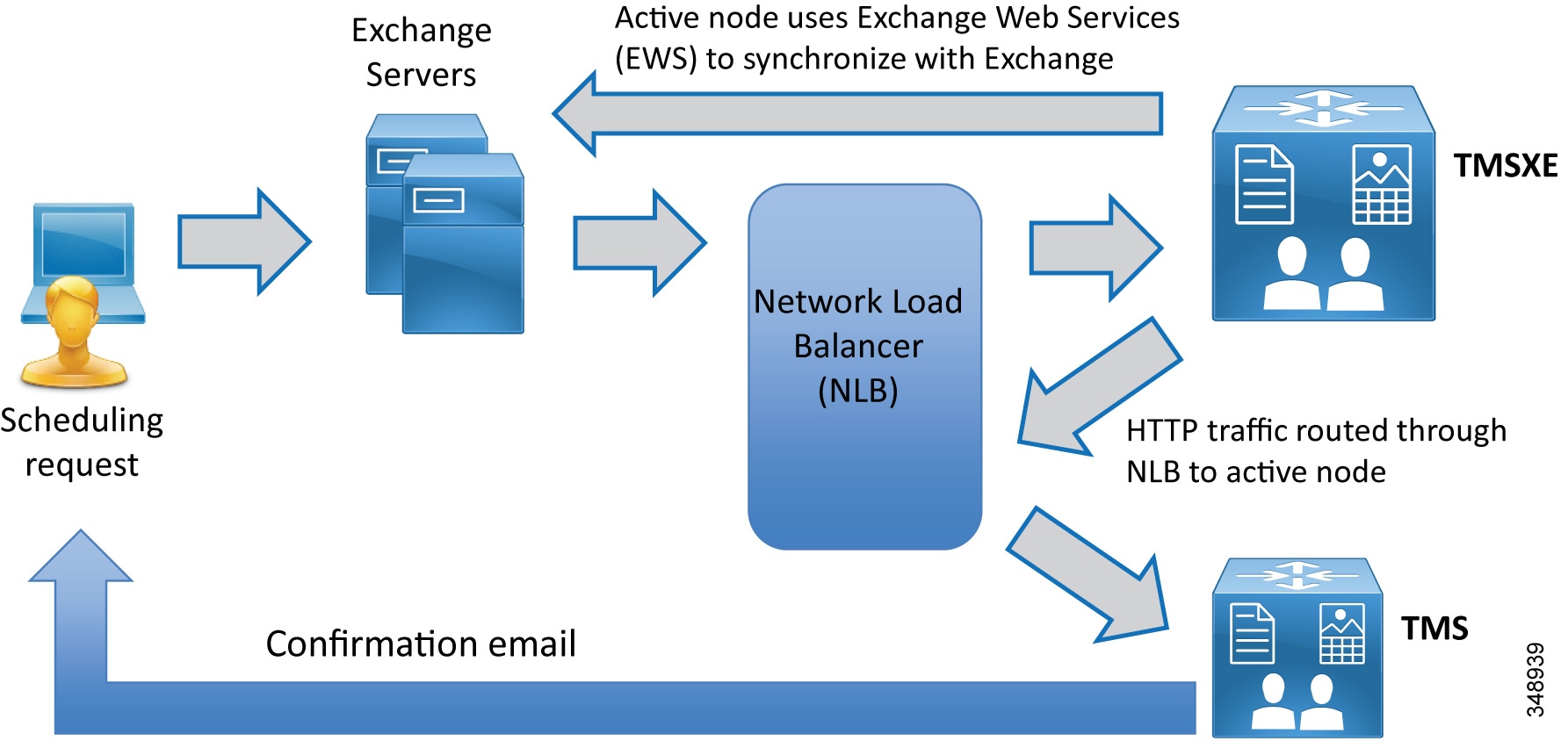
Once the per-system option key has been activated in Cisco TMS, the Allow Remote Bookings setting determines whether each system is using a license. This setting allows the administrator to select which endpoints are able to be booked by end users and consume one of the individual endpoint licenses. This setting is void and hidden if the Application Integration Package option is used.
Before endpoints can be added to Cisco TMSXE, they must be represented by a room mailbox in Exchange. To simplify TMSXE setup, we recommend using the endpoint's Cisco TMS display name as the mailbox name (with any spaces removed). This provides commonality across all methods by which end users would see the system name appear.
Special Notes About Privacy Features of Exchange:
All room mailboxes added to Cisco TMSXE must be configured to handle booking subjects and privacy settings in the same way. This means that the following settings must be applied to either all or none of the mailboxes:
We recommend not using this feature so that support staff is able to identify a particular meeting in the Conference Control Center. Also, this will allow the meeting title to appear on the One Button to Push interface of capable endpoints.
Use of this setting should be considered very carefully, and will depend upon organizational culture and practices. Keep in mind that if one person schedules meetings for multiple groups, those meetings will be listed by that scheduler's user name and not by the meeting subject, which might be more beneficial. On the other hand, if meetings are scheduled by their respective hosts, then it would be easy to identify "Bob's meeting" instead of remembering the specific meeting title. For most organizations, we recommend not using this setting.
While the "private" flag is respected within the Outlook client, it is not supported by Cisco TMS, and meeting subjects will be freely viewable:
–![]() On endpoints that support the Meetings calendar, if other individuals also have use of a room used for a meeting where the subject title should not be public within the organization. (For example, if a "Merger meeting" for the chief executive is scheduled in a room also used by lower-level employees who would not need to have knowledge of a pending merger, those lower-level employees would be able to see the meeting on a room system calendar.)
On endpoints that support the Meetings calendar, if other individuals also have use of a room used for a meeting where the subject title should not be public within the organization. (For example, if a "Merger meeting" for the chief executive is scheduled in a room also used by lower-level employees who would not need to have knowledge of a pending merger, those lower-level employees would be able to see the meeting on a room system calendar.)
–![]() If a booking that has a "private" flag in Exchange has its participants or recurrence pattern modified in Cisco TMS, the "private" flag will be removed when these changes are replicated to Exchange.
If a booking that has a "private" flag in Exchange has its participants or recurrence pattern modified in Cisco TMS, the "private" flag will be removed when these changes are replicated to Exchange.
- Create a TMSXE user in Active Directory and import that user into TMS.
- In TMS, the user needs to be in a new or existing group with the following permissions enabled under Booking:
Cisco TMSXE and TMS communicate using HTTPS. The certificate also allows for secure communications between the TMSXE server and the Exchange environment. As with the TMS application server, the same certificate is loaded on both the active and passive nodes of TMSXE, and the certificate DNS entry points to the entry of the Network Load Balance address used for TMSXE.
- Select the TMS Booking Service.
- Select the appropriate redundancy option for active or passive nodes.
- Complete the software installation on both active and passive nodes.
Once both the active and passive nodes have been installed, configure the Network Load Balancer with the probe URL for each node.
Configure TMS connection information using the TMSXE account created in Active Directory to allow the TMSXE application to communicate with the TMS application.
Configure Exchange Web Services (EWS) to allow TMSXE to communicate with the Exchange servers for user and resource mailboxes. The credentials used for this connection are also the same TMSXE credentials used elsewhere.
Align Exchange resources to TMS System IDs. This may be done individually or by using a.csv file as outlined in the latest version of the Cisco TelePresence Management Suite Extension for Microsoft Exchange Deployment Guide, available at
https://www.cisco.com/c/en/us/support/conferencing/telepresence-management-suite-extensions/products-installation-guides-list.html
Summary
After you complete the deployment tasks outlined above, Cisco TMS will be configured to communicate with Cisco Meeting Server for scheduled conferencing.
6. Deploy Cisco Meeting Server Spaces
This section describes the major tasks required to deploy Cisco Meeting Server Spaces.
Overview
| Deployment Tasks for Unified CM for Cisco Meeting Server Permanent Conferences: 1. 2. 3. |
| Deployment Tasks for Cisco Meeting Server to Create Spaces: 4. |
Deployment Considerations
Cisco Meeting Server Spaces are similar to permanent conferences created in the TelePresence infrastructure that resides in the enterprise's data center. Each Space has a unique set of video addresses that a user can call into to start a meeting at any time, and the video addresses can be in the format of numeric aliases or SIP URIs. Each Space can be associated with an individual user and can be created through LDAP user synchronization.
Cisco Meeting Server Spaces provide an easy way for participants to join a conference regardless of where those participants are located. Everyone dials into the same virtual meeting room from their laptop, telepresence room, desktop endpoint, or mobile device.
Deploying Spaces involves the deployment of Unified CM and Cisco Meeting Server. The following sections describe the high-level process for deploying each component for Spaces.

Tip![]() Before deploying Spaces, decide on the format of the conference aliases (numeric or SIP URI).
Before deploying Spaces, decide on the format of the conference aliases (numeric or SIP URI).
Deployment Tasks for Unified CM for Cisco Meeting Server Permanent Conferences
The main function of Unified CM is to handle call routing to and from Cisco Meeting Server. Connect Unified CM to Cisco Meeting Server with a SIP trunk enabled for Early Offer. (Use the same trunk as previously configured for scheduled conferences: SIP_TRUNK_CMS1.) When a user dials the Space alias, the call is sent to Call Bridge on Cisco Meeting Server via the SIP trunk. Similarly, Cisco Meeting Server can send calls to Unified CM through the SIP trunk for auto-dial participants. The conference alias has two formats: SIP URI or numeric. The dial plan design should include the call routing for both the numeric alias and SIP URI for Spaces. For dial plan design details, refer to the Call Control chapter.
A Cisco Meeting Server Space can be created for each individual user, and the Space numeric alias can be based upon the user's DID number. Table 3-23 shows the Space numeric alias ranges for a deployment using the dial plan example from Call Control chapter.
|
|
|
|
|---|---|---|
For numeric aliases, configure a route pattern for each site that routes to the Cisco Meeting Server route list for permanent conferences, as shown in Table 3-24 .
|
|
|
|
|
|---|---|---|---|
For SIP URIs, use the specified domain as the domain part when provisioning users. The domain configured in this document is cms.ent-pa.com. For example, participants can dial <username> .space@cms.ent-pa.com to join the conference on Cisco Meeting Server. Web app users are also reachable by dialing <username> @cms.ent-pa.com, for example, from a Unified CM registered device. Configure a Domain Routing SIP Route Pattern with the Cisco Meeting Server domain that routes calls to the Cisco Meeting Server route list for permanent conferences, as shown in Table 3-25 .
|
|
|
|
|---|---|---|
Deployment Tasks for Cisco Meeting Server to Create Spaces
Note![]() The tasks in this section are deployed using Cisco Meeting Server API Navigator available in the web user interface of the Cisco Meeting Server. For API details, refer to the latest version of the Cisco Meeting Server API Reference Guide, available at https://www.cisco.com/c/en/us/support/conferencing/meeting-server/products-programming-reference-guides-list.html.
The tasks in this section are deployed using Cisco Meeting Server API Navigator available in the web user interface of the Cisco Meeting Server. For API details, refer to the latest version of the Cisco Meeting Server API Reference Guide, available at https://www.cisco.com/c/en/us/support/conferencing/meeting-server/products-programming-reference-guides-list.html.
Cisco Meeting Server must have the Multiparty licenses applied before it can host conferences. Each user should be given a license if Personal Multiparty Plus (PMP+) is desired. To assign PMP+, the user should be associated with a user profile object that has the hasLicense field set to true. If the hasLicense field is false or does not exist in the user profile object, the user has no license and Shared Multiparty Plus (SMP+) will be used. User profiles specify the capabilities for the users. This can also be accomplished by provisioning the user in Cisco Meeting Management. In Cisco Meeting Management provisioning, when adding a user import select User properties. Assign Personal Multiparty Plus (PMP+) to imported users. Administrators can also use the API to create a userProfile object (POST /userProfiles) using the parameters as listed in Table 3-26 , and set the hasLicense field to true.
|
|
|
|
|---|---|---|
All users in Cisco Meeting Server reside in the LDAP directory. The user profile object (created previously) should be used as one of the parameters to synchronize the users from the directory to Cisco Meeting Server, and all imported users will be associated with that user profile. The ldapServers, ldapMappings, and ldapSources objects are required to create the user synchronization process.
ldapServers specifies the location, credentials, and other attributes to access the server. Use the parameters as listed in Table 3-27 to create the ldapServers object (POST /ldapServers).
|
|
|
|
|---|---|---|
ldapMappings allows you to specify the attributes related to the Space; for example, name, username, URI, and so forth. The attributes can be created based upon the attributes from Microsoft Active Directory (see Table 3-28 ). Use the parameters as listed in Table 3-28 to create the ldapMappings object (POST /ldapMappings).
|
|
|
|
|---|---|---|
Note that the prefix for Space secondary URI varies depending on the site, and the last three digits are extracted from the user's DID number. Using the dial plan example from the Call Control chapter, the SJC site has prefix 80044, RTP site has prefix 80051, and RCD site has prefix 80065. Hence, the ldapMappings object will be created three times, one for each site.
After importing the user with the mappings in Table 3-28 , the user has the username <username> @cms.ent-pa.com, which can be used to sign in to the Cisco Meeting App. The user has an associated Space with primary URI <username> .space@ <domain> and secondary URI 80044XXX@ <domain>. The domain is based on the domain name configured in the call matching table for incoming calls inside Cisco Meeting Server (see Table 3-30 ).
LDAP Sources are used to combine the LDAP Server, LDAP Mapping, user profile, and LDAP filter into a single source so that a specific group of users can be imported into Cisco Meeting Server. Use the parameters as listed in Table 3-29 to create the ldapSources object (POST /ldapSources).
|
|
|
|
|---|---|---|
Note that the ID of the object can be retrieved using the GET operation. For example, to retrieve the ID of the ldapMapping object, use GET /ldapMappings. Also, each site will have different filter so that users at each site will be imported based on the Active Directory group to which the users belong. For example, SJC users should belong to sjcgroup Active Directory group, RTP users should belong to rtpgroup Active Directory group, and RCD users should belong to rcdgroup Active Directory group. Hence, three ldapSource objects will be created using the site-specific ldapMapping and filter.
After all LDAP Sources are created, use the ldapSyncs object (POST /ldaySyncs) to start the user synchronization immediately. When the synchronization is done, users from all sites and a Space for each imported user should be created in Cisco Meeting Server.
Note![]() Spaces can be created using an API or manually by users in the Cisco Meeting App.
Spaces can be created using an API or manually by users in the Cisco Meeting App.
Next, create dial plan rules in Cisco Meeting Server to handle incoming calls. Browse to one of the web admin interfaces and add the domains to the call matching table of incoming calls configured in the web interface (Configuration -> Incoming Calls) using the values in Table 3-30 . The domains are cms.ent-pa.com and top level domain ent-pa.com match incoming calls to sip URIs that are mapped according to the information in table Table 3-30 , and FQDN and IP address of all Call Bridges (us-cms-1.ent-pa.com, us-cms-2.ent-pa.com and us-cms-3.ent-pa.com).
|
|
|
|
|
|
|
|---|---|---|---|---|---|
All SIP URI calls that are dialed to cms.ent-pa.com are either for the Spaces or Cisco Meeting App users. Users calling into the Spaces using numeric dialing will hit the rules for the top level domain or the Call Bridge FQDNs or IP addresses.
Summary
After you complete the deployment tasks outlined above, users can sign into their Space using Web app to specify PIN, add members, and customize other preferences. Users can then dial the SIP URI or numeric alias to start the meeting.
7. Deploy Cisco Meeting Management
This section describes the major deployment tasks for Cisco Meeting Management.
Overview
| Deployment Tasks for Cisco Meeting Management: 1. 2. 3. 5. 6. |
Cisco meeting Management is the platform for managing the Cisco Meeting Server solution. Cisco Meeting Management displays active meeting information with controls for managing those meetings, manages Cisco Meeting Server licenses, as well as providing administrators the ability to provision users and space templates on managed Cisco Meeting Servers.
Deployment Considerations
Cisco Meeting Management is mandatory with Cisco Meeting Server 3.0 or later and requires no additional licensing. Cisco Meeting Management can manage a single CMS call bridge to multiple clustered call bridges. Sizing Cisco Meeting Management depends on the call volume expected and the size of the Cisco Meeting Server deployment. Cisco Meeting Management reports on license utilization and manages the licensing with Cisco Smart Software Licensing.
Cisco Meeting Management uses LDAP directory for user authentication and LDAP groups to map the user group that determines the user's role. At least 2 LDAP directory groups are required for the deployment, create one group (e.g. CMMAdmin) for the administrators and another group (e.g. CMMOperator) for the video operators. Then decide on which user should belong to which group and assign users to the corresponding groups before proceeding with first-time setup.
Deployment Tasks for Cisco Meeting Management
Deploy Cisco Meeting Management OVA
Meeting Management is available as an OVA file on cisco.com for all customers with a Cisco Meeting Server support contract. During the deployment of the Cisco Meeting Management OVA network settings are configured for the Cisco Meeting Management.
For details on first-time setup, refer to the latest version of the Cisco Meeting Management Installation and Configuration Guide, available at
https://www.cisco.com/c/en/us/support/conferencing/meeting-management/products-installation-guides-list.html
Connect Cisco Meeting Management to Cisco TMS
Cisco Meeting Management uses the TMS Booking API connection to retrieve information about upcoming TMS scheduled meetings as well as for access to the TMS address books. In the Cisco Meeting Management web interface go to Settings -> TMS and use the values shown in Table 3-31 for configuration information.
|
|
|
|
|---|---|---|
Then go to Settings -> NTP and add the NTP server. The same NTP server should be used for Cisco Meeting Server and TMS in order to synchronize the time among the three components.
Add Cisco Meeting Server call bridges to be managed
Add all call bridges within the cluster into Cisco Meeting Management for monitoring and management. Go to the Servers page and add a call bridge (any call bridge within the cluster) using the values in Table 3-32 for the configuration.
|
|
|
|
|---|---|---|
Use the auto-discovered Call Bridge option to add the rest of Call Bridges within the cluster into Cisco Meeting Management. Cisco Meeting Management needs to know the Call Bridge that is added to TMS in order to show the scheduled meetings. To do so, the administrator needs to associate the Cisco Meeting Server cluster with TMS. Click on the Associate cluster with TMS link on top of the cluster table and use the values in Table 3-33 for the configuration.
|
|
|
|
|---|---|---|
Configure licensing mode
As of version 3.0 Cisco Meeting Management is required for licensing the Cisco Meeting Server. There are 3 modes for licensing the Cisco Meeting Server:
- Traditional licensing; which requires that valid license files are installed on all call bridges
- Smart licensing; which requires a Smart Account with the appropriate licensing in the Smart licensing Virtual account
- No licensing; used in resilient Cisco Meeting Management deployments
Note![]() All Cisco Meeting Servers must be configured to an instance of Cisco Meeting Management. In resilient deployments of Cisco Meeting Management only configure 1 Cisco Meeting Management for Smart Licensing. Having 2 Cisco Management server configured for Smart Licensing results in double counting of licenses available in the Smart account.
All Cisco Meeting Servers must be configured to an instance of Cisco Meeting Management. In resilient deployments of Cisco Meeting Management only configure 1 Cisco Meeting Management for Smart Licensing. Having 2 Cisco Management server configured for Smart Licensing results in double counting of licenses available in the Smart account.
To enable Traditional licensing for call bridges:
Select Traditional from the Licensing tab in Cisco Meeting Management Licensing page
To enable Smart licensing for call bridges:
Sign in to your Cisco Smart Software Manager account and generate a token. Copy this token and enter it into the Cisco Meeting Management when prompted.
Go to the Settings > Licensing tab in Cisco Meeting Management and select Change
Select Smart Licensing and Save
Select Register and paste the token copied previously
Choose Smart Licensing and Save
Once registered go to the Cisco Meeting Management Licensing page and allocate Cisco Meeting Server licenses as required for the deployment
Note![]() Cisco Meeting Management has a Trial option that does not require licensing and is useful for testing CMS or optional features.
Cisco Meeting Management has a Trial option that does not require licensing and is useful for testing CMS or optional features.
Cisco meeting management enforces license compliance at different time thresholds. See Figure 3-17 for the enforcement work flow to maintain compliance.
Figure 3-17 Licensing enforcement workflow

Configure LDAP settings and LDAP user groups
All users in Cisco Meeting Management reside in the LDAP directory that Meeting Management utilizes for user authentication. Therefore, after logging into the portal for the first-time, configure the LDAP server, user search base, and authentication information using the values in Table 3-34 .
|
|
|
|
|---|---|---|
|
|
||
|
|
||
|
|
||
Cisco Meeting Management uses the LDAP group to map the user group and thus determine the user access privilege in the portal. At this point, map the LDAP group (CMMGroup) created previously for the administrator so that users can login to continue the setup. Use the example shown in Table 3-35 to configure the group mapping.
|
|
|
|
|---|---|---|
After the first-time setup is complete, log into the Cisco Meeting Management portal using one of the administrator (user in CMMAdmin LDAP group) credentials. Once logged in, go to Settings -> CDR to set up the CDR receiver address using the IP address or FQDN of the Cisco Meeting Management server (for example, https://10.x.x.68). Cisco Meeting Management uses this address to construct the CDR receiver URI string in the Call Bridges to receive call related events.
Go to Users -> User Groups and use the values shown in Table 3-36 for the configuration.
|
|
|
|
|---|---|---|
Configure CMS web app user provisioning
This section describes the major tasks for configuring Cisco Meeting Management to enable user provisioning.
An administrator can use Cisco Meeting Management to provision users and spaces for Cisco Meeting Servers managed by the Cisco Meeting Management. Cisco Meeting Management leverages LDAP to enable provisioning.
Supported LDAP implementations are:
Note![]() If Cisco Meeting Server LDAP has been configured by using the Cisco Meeting Server web user interface the configuration must be removed from Cisco Meeting Server web user interface configuration page before configuring Cisco meeting Management for LDAP.
If Cisco Meeting Server LDAP has been configured by using the Cisco Meeting Server web user interface the configuration must be removed from Cisco Meeting Server web user interface configuration page before configuring Cisco meeting Management for LDAP.
Configuration Tasks for Cisco Meeting Management user/space provisioning
Refer to Table 3-34 in Deployment Tasks for Cisco Meeting Management for the LDAP details needed to configure provisioning in Cisco Meeting Management.
The number of PMP+ licenses is also required.
Add LDAP server(s) for provisioning in Cisco Meeting Management by going to Servers > Setup provisioning
In the Servers page click Set up provisioning and enter details for the LDAP server(s)
Default port numbers for LDAP server
Note![]() Changes in configuration of Cisco Meeting Management must be committed, otherwise, changes are lost if Cisco Meeting Management is restarted.
Changes in configuration of Cisco Meeting Management must be committed, otherwise, changes are lost if Cisco Meeting Management is restarted.
Import users by going to the Provisioning page Import users and define which users will be imported for provisioning. The users are a subset of users in an LDAP server configured above. Multiple user imports can be configured as needed. However, it is recommended that users are only configured in one import as Cisco Meeting Management cannot differentiate between users to add to groups.
- Go to Servers > Set up provisioning
- On Import users tab select Add user import
- Add a name that distinguishes the import defined.
- From the drop down menu for LDAP servers select the LDAP server to apply the user import.
- Enter Base DN for the search starting point for users
- Enter LDAP search filters as desired.
- Enter Login user mapping as desired.
- Enter Display name as desired.
- For each group of users sign-in user name mapping ie: $sAMAccountName$@example.com and display name mapping ie: $cn$.
- If desired check the Assign Personal Multiparty Plus (PMP+) license to imported users check box.
Once provisioning for users is configured additional provisioning permissions can be defined.
Automatically create spaces for users:
This configuration automatically creates spaces for users using existing space templates or templates created for automatically created spaces. Rules are created to map subsets of users to templates. The spaces created automatically are not activated until the provisioned web app users logs and selects to enable the space.
The ability for provisioned Cisco Meeting Server web app users to create spaces is done by assigning specific templates to specific user imports. On the Provisioning page > Allow users to create spaces tab templates are selected or created and assigned to specific groups of users.
In order for users to be imported and have the provisioning settings applied Cisco Meeting Management and the configured LDAP servers must be synchronized. Cisco meeting Management LDAP synch can also be used for synchronizing any changes to LDAP such as added or removed users.
On the Provisioning page under the LDAP sync tab LDAP sync can be initiated as well as scheduled. Syncs can be triggered manually as needed from this tab or can be scheduled at regular intervals.
Restart Cisco Meeting Management to save configured settings
Changes will not be applied before you have committed them. After you have committed the changes, template settings will take effect immediately. Changes to LDAP server details and any changes that affect users will take effect next time the Meeting Server is synchronized with the LDAP servers.
Create a backup of Cisco Meeting Management
It is recommended that you always create a new backup before you make any changes to Meeting Management. The backup contains:
In the Cisco Meeting Management interface go to Settings > Backup and Restore > Download backup file. Save the file in a secure location.
Summary
After you complete the deployment tasks outlined above, video operators can login to the Cisco Meeting Management portal to monitor and manage meetings for Cisco Meeting Server. CMS web app users are also provisioned as required for user spaces, templates and permissions for creating their own spaces.
Related Documentation
For additional information about Cisco Meeting Server, refer to the latest version of the following documents, available at the links provided below:
https://www.cisco.com/c/en/us/support/conferencing/meeting-server/products-installation-and-configuration-guides-list.html
https://www.cisco.com/c/en/us/support/conferencing/meeting-server/products-programming-reference-guides-list.html
https://www.cisco.com/c/en/us/support/conferencing/meeting-server/products-release-notes-list.html
- Cisco Meeting Management documentation https://www.cisco.com/c/en/us/support/conferencing/meeting-management/series.html - Configuration
- Cisco Meeting Server web app documentation https://www.cisco.com/c/en/us/support/conferencing/cisco-meeting-app/series.html
 Feedback