- What’s New in This Chapter
- Prerequisites
- Unified Messaging with Cisco Unity Connection
- Architecture
- Cisco Unity Connection Deployment Process
- Prerequisites
- Deployment Overview
- 1. Provision the Unity Connection Cluster
- Publisher
- Subscriber
- Unity Connection Mailbox Stores
- Prerequisite for Unity Connection Cluster Deployment When the Servers Are to Be Installed in the Same Building
- Prerequisite for Unity Connection Cluster Deployment When the Servers Are to Be Installed in Separate Buildings
- To Deploy Unity Connection Cluster
- 2. Configure Unified CM for Unity Connection Integration
- 3. Unity Connection Base Configuration
- Service Activation
- Database Replication
- Unified CM Integration
- Voicemail Port Audio Codec Configuration
- System Settings
- Phone System Settings
- Port Group Settings
- Voice Messaging Port Sizing Considerations
- Port Settings
- Active Directory Integration
- Unity Connection Partitions and CSS
- Restriction Tables
- Class of Service
- User Provisioning
- Unity Connection User Self Enrollment
- 4. Enable Single Inbox
- Perquisites for Enabling Single Inbox with Unity Connection
- Unity Connection Certificate Management
- Confirm the Exchange Authentication and SSL Settings for Unity Connection
- Configure SMTP Proxy Addresses in Unity Connection
- Create Unified Messaging Services Account in Active Directory and Grant Permissions for Unity Connection
- SMTP Smart Host
- Unified Messaging Service
- Unified Messaging Account
- Voice Mail User COS
- Install ViewMail for Outlook on User Workstations
- 5. Enable Visual Voicemail
- 6. Voice Mail in SRST Mode
- 7. HTTPS Internetworking of Two Unity Connection Clusters
Voice Messaging
This chapter describes the voice messaging services included in the Preferred Architecture for Enterprise Collaboration. This chapter explains how to implement Unified Messaging with Cisco Unity Connection. It contains a description of the core architecture as well as details about the deployment process.
What’s New in This Chapter
Table 5-1 lists the topics that are new in this chapter or that have changed significantly from previous releases of this document.
|
|
|
|
|---|---|---|
Prerequisites
Before deploying the core applications for the Preferred Architecture, ensure that:
- Cisco Unified Communications Manager (Unified CM) is deployed and functioning.
- Microsoft Active Directory is installed, and the integration for each application is understood.
- The Call Control chapter of this document is understood and implemented.
Unified Messaging with Cisco Unity Connection
Cisco Unity Connection enables unified messaging for the Cisco Preferred Architecture for Enterprise Collaboration. This section provides the information and instructions for deploying Unity Connection for voice messaging and unified messaging along with features such as single inbox and visual voicemail. This section also covers networking between two Unity Connection clusters.
Core Components
Key Benefits
–![]() Cisco Unified IP Phones, TelePresence endpoints, Jabber, and mobile devices
Cisco Unified IP Phones, TelePresence endpoints, Jabber, and mobile devices
Architecture
The Preferred Architecture uses a centralized deployment model for voice messaging and call processing, as described in this section.
Centralized Messaging and Centralized Call Processing
As shown in Figure 5-1, with centralized messaging Unity Connection is located in the same site as the Unified Communications Manager (Unified CM) cluster. Remote branch sites located over the WAN from the central site rely on the centralized Unity Connection for unified messaging services. Unity Connection integrates with Unified CM using SIP for call control and RTP for the media path. Each Unity Connection cluster consists of two server nodes providing high availability and redundancy.
Figure 5-1 Architecture Overview

At the remote branch site, Cisco Unified Survivable Remote Site Telephony (SRST) is installed as a backup call agent, which is integrated with the central Unity Connection server. In the event of an IP WAN outage, all the phones at the remote branch register with SRST, which is preconfigured to send all the unanswered and busy calls to the central Unity Connection server via the PSTN.
Role of Unified CM
Unified CM provides call control capabilities and forwards calls to Unity Connection in the event that a called phone is either busy or unanswered. If a user presses the message button on the phone or dials the voicemail pilot number from an outside network, then Unified CM routes the call to Unity Connection.
Role of Unity Connection
In a centralized messaging deployment, Unity Connection provides users with the ability to store and retrieve voicemails. Typically calls forwarded to Unity Connection are direct calls or are due to a called extension that is either busy or unanswered. Message Waiting Indicator (MWI) is displayed on the endpoint for any new messages stored for the user. With each call, the following call information is typically passed between the phone system and Unity Connection:
- The extension of the called party
- The extension of the calling party (for internal calls) or the phone number of the calling party (if it is an external call and the phone system supports caller ID)
- The reason for the forward (the extension is busy, does not answer, or is set to forward all calls)
If the call is forwarded because the called party did not answer the call, Unity Connection plays the called user’s standard greeting. If the call was forwarded because the called phone was busy, Unity Connection plays the called user’s busy greeting.
Unity Connection handles direct calls differently than forwarded calls. When Unity Connection receives a call, it first attempts to determine whether the caller is a user. It does this by identifying whether the caller ID matches a user’s primary or alternate extension. If Unity Connection finds a match, it assumes that a user is calling and it asks for that user’s voicemail PIN. If Unity Connection determines that the caller ID is not associated with a user, then the call is sent to the opening greeting. An opening greeting is the main greeting that outside callers hear when they reach the Unity Connection auto-attendant.
Role of Microsoft Exchange
Unity Connection is integrated with Microsoft Exchange to enable the Single Inbox feature. Single Inbox in Unity Connection enables unified messaging and synchronizes voice messages between Unity Connection and Microsoft Exchange. This enables users to retrieve voicemail using their email client.
This chapter focuses on Unified Messaging with Microsoft Exchange. Unity Connection can also be integrated with IBM Lotus Sametime instant messaging application, allowing users to play their voice messages using Lotus Sametime. For more information on this topic, refer to the Unity Connection documentation available at
High Availability for Unified Messaging
Figure 5-2 shows Unity Connection in an active/active pair, allowing the Unity Connection servers to be installed in the same or separate buildings to provide high availability and redundancy. Both servers in the active/active pair are running Unity Connection, both accept calls and HTTPS requests, and both servers store user information and messages. In the event that only one server in the clustered pair is active, Unity Connection preserves the complete end-user functionality, including voice calls and HTTPS requests. However, Unity Connection port capacity for calls will be reduced by half, to that of a single server.
Figure 5-2 Unity Connection Cluster
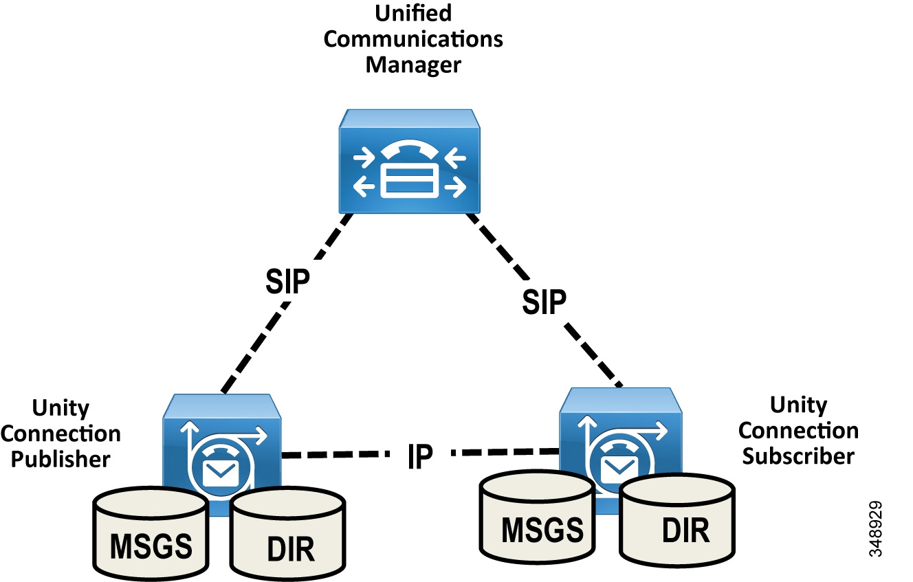
All user client and administrator sessions (for example, IMAP and Cisco Personal Communications Assistant) and administration traffic (for example, Cisco Unity Connection Administration, the Bulk Administration Tool, and backup operations) connect to the Unity Connection publisher server. If the publisher server stops functioning, the user client and administrator sessions can connect to the Unity Connection subscriber server.
This topology requires two separate Unified CM SIP trunks pointing to each Unity Connection server node in the cluster. This configuration provides both high availability and redundancy. Unified CM should be configured to route all calls to the Unity Connection subscriber node first. If the subscriber server is unavailable or all the ports of the subscriber are busy, then calls are routed to the publisher node. Given the SIP integration between Unified CM and Unity Connection, trunk selection is achieved via Unified CM route pattern, route list, and route group constructs (see Figure 5-3). Both trunks are part of the same route group and assigned to the same route list, and the trunks within the route group are ordered using a top-down trunk distribution algorithm. This approach allows Unified CM to control the preference of the Unity Connection server node selection during both normal and failover operation.
Figure 5-3 Unity Connection SIP Trunk Selection

Unity Connection supports using Single Inbox with Microsoft Exchange Database Availability Groups (DAGs) for high availability. The DAGs are deployed according to Microsoft recommendations. Unity Connection also supports connecting to a client access server (CAS) array for high availability. This section does not cover Microsoft Exchange high availability deployment. For more information about Exchange high availability deployments, refer to the Microsoft Exchange product information available at https://www.microsoft.com/.
Licensing Requirements
The licenses for Unity Connection are managed by Cisco Smart Software Manager. To use the licensed features on Unity Connection, valid licenses for the features must be available within the customer's Cisco Smart Software Manager licensing account, and Unity Connection must communicate with the Cisco Smart Software Manager service to access and use the licenses. Cisco Smart Software Manager provides web-based centralized, simplified, and enterprise-wide management of user-based licensing.
Unified Messaging Requirements
- Unity Connection supports Microsoft Exchange, Microsoft Business Productivity Online Suite (BPOS) Dedicated Services, and Microsoft Office 365 cloud-based Exchange for Single Inbox.
- Exchange servers and Active Directory domain controllers/global catalog servers (DC/GCs) can be installed in any hardware virtualization environment supported by Microsoft. Refer to Microsoft Exchange product information available at https://www.microsoft.com/ for more information about supported hardware platforms.
- The Microsoft Exchange message store can be stored in any storage area network configuration supported by Microsoft. Refer to Microsoft Exchange product information available at https://www.microsoft.com/ for more information about supported storage area network.
- For every 50 voice messaging ports on each server, 7 Mbps of bandwidth is required between Unity Connection and Microsoft Exchange for message synchronization.
- The default Unity Connection configuration is sufficient for a maximum of 2,000 users and 80 milliseconds of round-trip latency between Unity Connection and the Exchange servers. For more than 2,000 users and/or more than 80 milliseconds of latency, you can change the default configuration. For more information, see the information on latency in the latest version of the Design Guide for Cisco Unity Connection, available at
https://www.cisco.com/c/en/us/support/unified-communications/unity-connection/products-implementation-design-guides-list.html
Scaling Unity Connection
A Unity Connection cluster consists of a maximum of two nodes, one publisher and one subscriber in an active/active deployment. Under normal operation, call processing load balancing does not occur in an active/active deployment. Unified CM is configured to route all calls to the Unity Connection subscriber server first. If all ports are busy or if the subscriber server is unavailable, then calls are routed to the publisher. When sizing Unity Connection, consider the following aspects:
- Total number of current and future users
- Required voice messaging storage capacity
- Number of voicemail ports supported with each platform
- Whether encryption is enabled
For more information on Unity Connection scaling, see the Sizing chapter.
Cisco Unity Connection Deployment Process
This section describes how to deploy Cisco Unity Connection in the Preferred Architecture.
Prerequisites
Before deploying the unified messaging architecture, ensure that:
- Cisco Unified CM is installed and configured for call control (see the Call Control chapter).
- Microsoft Exchange is installed and configured as an email server.
Deployment Overview
For the purposes of this Preferred Architecture, we assume a centralized messaging deployment model serving three sites in the US: SJC, RCD, and RTP. The deployment of centralized messaging starts with the Unity Connection cluster installation followed by further provisioning and configuration. To deploy centralized unified messaging with Cisco Unity Connection, perform the following tasks in the order listed here:
1. Provision the Unity Connection Cluster
2. Configure Unified CM for Unity Connection Integration
3. Unity Connection Base Configuration
7. HTTPS Internetworking of Two Unity Connection Clusters

Note![]() Only non-default and other configuration field values are specified in this document. If a field configuration value is not mentioned, then the default value should be assumed.
Only non-default and other configuration field values are specified in this document. If a field configuration value is not mentioned, then the default value should be assumed.
1. Provision the Unity Connection Cluster
When clustering Unity Connection server nodes, one server is designated as the publisher server in the server pair while the other server is designated as the subscriber server.
Publisher
In Unity Connection only two servers are supported in a cluster for active/active high availability. The publisher server is the first to be installed, and it publishes the database and message store, replicating this information to the other subscriber server in the cluster.
Subscriber
Once the software is installed, the subscriber server node subscribes to the publisher to obtain a copy of the database and message store.
Unity Connection Mailbox Stores
During installation, Unity Connection automatically creates:
- A directory database for system configuration information (user data, templates, classes of service, and so forth).
- A mailbox store database for information on voice messages (who each message was sent to, when it was sent, the location of the WAV file on the hard disk, and so forth).
- An operating system directory for voice message WAV files.
Prerequisite for Unity Connection Cluster Deployment When the Servers Are to Be Installed in the Same Building
- For inbound and outbound calls to Unity Connection, the TCP and UDP ports of the firewall must be open as listed in the chapter on IP Communications Required by Cisco Unity Connection in the latest version of the Security Guide for Cisco Unity Connection, available at
https://www.cisco.com/c/en/us/support/unified-communications/unity-connection/products-maintenance-guides-list.html
- For a cluster with two virtual machines, both must have the same virtual platform overlay.
- The servers must not be separated by a firewall.
- Both Unity Connection servers must be in the same time zone.
- Both Unity Connection server nodes must integrate to the same phone system.
- Both Unity Connection servers must have the same enabled features and configurations.
Prerequisite for Unity Connection Cluster Deployment When the Servers Are to Be Installed in Separate Buildings
- For inbound and outbound calls to Unity Connection, the TCP and UDP ports of the firewall must be open as listed in the chapter on IP Communications Required by Cisco Unity Connection in the latest version of the Security Guide for Cisco Unity Connection, available at
https://www.cisco.com/c/en/us/support/unified-communications/unity-connection/products-maintenance-guides-list.html
- For a cluster with two virtual machines, both must have the same virtual platform overlay.
- Both Unity Connection server nodes must integrate to the same phone system.
- Both Unity Connection servers must have the same enabled features and configurations.
- Depending on the number of voice messaging ports on each Unity Connection server node, the connectivity between the server nodes must have the following guaranteed bandwidth with no steady-state congestion:
–![]() For every 50 voice messaging ports on each server, 7 Mbps of bandwidth is required.
For every 50 voice messaging ports on each server, 7 Mbps of bandwidth is required.
–![]() Maximum round-trip latency must be no more than 150 milliseconds (ms).
Maximum round-trip latency must be no more than 150 milliseconds (ms).
To Deploy Unity Connection Cluster
- Determine which VMware Open Virtual Archive (OVA) template you want to deploy for the Unity Connection node based on the maximum number of ports and the maximum number of users. Refer the section on Scaling Unity Connection.
- Add both the Unity Connection nodes as host A records in the enterprise domain name service (DNS) server. For example, set the publisher Unity Connection hostname as US-CUC1.ent-pa.com and the subscriber hostname as US-CUC2.ent-pa.com.
- Determine the network parameters required for the installation:
–![]() Host name, IP address, network mask, and default gateway. Ensure that the hostname and IP address match the previous DNS configuration.
Host name, IP address, network mask, and default gateway. Ensure that the hostname and IP address match the previous DNS configuration.
–![]() Network Time Protocol (NTP) server IP addresses
Network Time Protocol (NTP) server IP addresses
- Download the appropriate OVA file from the Cisco website.
- Deploy the Unity Connection publisher and subscriber server nodes using the VMware vSphere Client.
- Install the Unity Connection publisher and subscriber nodes with Cisco Prime Collaboration Deployment.
For details, see the section on Cisco Prime Collaboration Deployment in the Collaboration Management Services chapter.
Note![]() Optionally, the Unity Connection cluster can be deployed manually. In that case, first deploy the Unity Connection publisher node using the preferred OVA on the VMWare host, then install the Unity Connection package manually on this publisher node. Once the publisher node installation completes, repeat the process for the subscriber node (deploy the OVA on the VMWare host and manually installing the Unity Connection package).
Optionally, the Unity Connection cluster can be deployed manually. In that case, first deploy the Unity Connection publisher node using the preferred OVA on the VMWare host, then install the Unity Connection package manually on this publisher node. Once the publisher node installation completes, repeat the process for the subscriber node (deploy the OVA on the VMWare host and manually installing the Unity Connection package).
2. Configure Unified CM for Unity Connection Integration
Before Unity Connection communicates with Unified CM, certain tasks must be performed on Unified CM. Unity Connection communicates to Unified CM over a SIP trunk. This section provides an overview of the tasks required to integrate Unified CM with Unity Connection.
Unity Connection Application Username and Server for End User PIN Synchronization
To simplify end user PIN management, enable PIN synchronization between Unified CM and Unity Connection. With PIN synchronization an end user can use the same PIN for multiple purposes, including voice mail access, Extension Mobility, and Conference Now. The PIN is synchronized whether a user changes their PIN number using the Unified CM Self-Care Portal or the Cisco Unity Connection Personal Communications Assistant (PCA).
First, confirm that an application user is configured to match the Unity Connection system administrator account username and password. (For example, administrator.) Assuming the system administrator account names and passwords are the same for Unified CM and Unity Connection, this account is already configured.
Next, add new Unity Connection application servers for both publisher and subscriber nodes as shown in Table 5-2 .
Note![]() When enabling end-user PIN synchronization between Unified CM and Unity Connection, it is important make sure the assigned PIN authentication rule on Unified CM matches the assigned voicemail authentication rule on Unity Connection in terms of minimum credential length and expiration. Failure to align these authentication rules can result in PIN synchronization errors and login failures, and might require administrator intervention.
When enabling end-user PIN synchronization between Unified CM and Unity Connection, it is important make sure the assigned PIN authentication rule on Unified CM matches the assigned voicemail authentication rule on Unity Connection in terms of minimum credential length and expiration. Failure to align these authentication rules can result in PIN synchronization errors and login failures, and might require administrator intervention.
Note![]() Unity Connection and Unified CM must both contain the far-end server or root CA certificate loaded to tomcat-trust in order for PIN synchronization to work. For more details on certificate management, refer to the Security chapter.
Unity Connection and Unified CM must both contain the far-end server or root CA certificate loaded to tomcat-trust in order for PIN synchronization to work. For more details on certificate management, refer to the Security chapter.
SIP Trunk Security Profile
As far as media and signaling encryption is concerned, this guide assumes they are not used and instead non-secure SIP trunks are implemented between Unified CM and Unity Connection server nodes. Create a new SIP Trunk Security Profile for Unity Connection with device security mode set to Non Secure. Table 5-3 lists the SIP trunk security profile settings.
SIP Profile
Configure a SIP profile for the SIP trunk to Unity Connection. Copy the standard SIP profile and rename it to Unity Connection SIP Profile. Select the checkbox Use Fully Qualified Domain Name in SIP Requests to prevent the IP address of the Unified CM server from showing up in SIP calling party information sent by Unified CM. Ensure that the checkbox Enable OPTIONS Ping to monitor destination status for Trunks with Service Type "None (Default)" is checked so that the system tracks the status of connectivity to the Unity Connection node.
When the OPTIONS Ping is enabled, each node running the trunk's SIP daemon will periodically send an OPTIONS Request to each of the trunk's destination IP addresses to determine its reachability and will send calls only to reachable nodes. A destination address is considered to be "out of service" if it fails to respond to an OPTIONS Request, if it sends a Service Unavailable (503) response or Request Timeout (408) response, or if a TCP connection cannot be established. The overall trunk state is considered to be "in service" when at least one node receives a response (other than a 408 or 503) from a least one destination address. SIP trunk nodes can send OPTIONS Requests to the trunk's configured destination IP addresses or to the resolved IP addresses of the trunk's DNS SRV entry. Enabling SIP OPTIONS Ping is recommended for all SIP trunks because it allows Unified CM to track the trunk state dynamically rather than determining trunk destination state on a per-node, per-call, and time-out basis.
SIP Trunk
Create two separate SIP trunks, one for each Unity Connection server node in the cluster. Table 5-4 lists the SIP trunk settings.
|
|
|
|
|---|---|---|
Enter the device pool for Unity Connection. (See the Call Control chapter.) |
||
This ensures that outbound calls using the SIP trunk do not require intra-cluster control signaling between Unified CM call processing subscribers. |
||
|
|
||
VoiceMail (Refer to the Call Control chapter for more about CSS configuration.) |
CSS assigned contains all the on-net destinations such as DIDs, non-DID numbers, and URI partitions. If the CSS does not include all these partitions, then the MWI Unsolicited Notify messages from Unity Connection will not reach user phones. |
|
This ensures that the redirecting Information Element, the first redirecting number, and the call forward reason are sent and accepted as a part of incoming messages. Unity Connection uses the first redirecting number to answer the call. |
||
|
|
||
This option determines whether Unified CM inserts a directory number, a directory URI, or a blended address that includes both the directory number and directory URI, in the SIP identity headers for outgoing SIP messages. |
||
This ensures that the redirecting Information Element, the first redirecting number, and the call forward reason are sent and accepted as a part of outgoing messages. Unity Connection uses the first redirecting number to answer the call. |
||
|
|
||
Enter the fully qualified domain name (FQDN) of Unity Connection server. |
||
See Table 5-3 . |
||
See the SIP Profile section. |
||
Route Group
Create a separate route group RG_CUC for the Unity Connection cluster. The route group contains the SIP trunks to the Unity Connection subscriber and publisher nodes. Ensure that the SIP trunk that connects to the subscriber node (US_CUC2_SIP_Trunk) appears first in the list, followed by the publisher node (US_CUC1_SIP_Trunk). The route group distribution algorithm should be set to the Top Down trunk selection method. A route group configured with the Top Down distribution algorithm ensures that the calls are always sent to the Unity Connection subscriber server node (US-CUC2) first. If the Unity Connection subscriber server node is busy or unavailable, then the calls are sent to the publisher server node (US-CUC1).
Route List
Create a separate route list RL_CUC for the Unity Connection cluster. The route list should contain only the Unity Connection route group (RG_CUC) created previously. Ensure that the options Enable this Route List and Run on all Active Unified CM Nodes are selected.
Route Pattern
Create a separate route pattern for the voicemail pilot number pointing to the Unity Connection route list created above. This number must match the voicemail pilot number. Table 5-5 shows the route pattern configuration example.
|
|
|
|---|---|
Voice Mail Pilot
The voicemail pilot number designates the directory number that users dial to access voice messages. Unified CM automatically dials the voicemail pilot number when a user presses the Messages button on an IP endpoint. A single voicemail pilot number is created for all three sites. Table 5-6 shows the voicemail pilot configuration example.
|
|
|
|---|---|
Voicemail users located at remote sites can check their messages from the PSTN by dialing the voicemail access number from their own DID range. A separate translation pattern is created to translate the voicemail PSTN access number to the voicemail pilot number. Table 6 shows the translation pattern configuration for the voicemail pilot.
|
|
|
|---|---|
|
|
|
Additional translation patterns would be created for other remote sites.
Voicemail Profile
A voicemail profile is assigned to each user's phone line on all endpoint devices and Extension Mobility profiles. The profile enables users to press the Messages button on an endpoint for one-touch access to the voicemail system. If Unity Connection is integrated with a single phone system, we recommend using the default voicemail profile. During the initial provisioning of a line on an endpoint device, the default voicemail profile (None) is assigned to the directory number. For the users who do not require voicemail access, no voicemail profile is assigned to their endpoint lines. Table 5-8 shows the settings for the voicemail profile configuration example.
|
|
|
|---|---|
3. Unity Connection Base Configuration
Service Activation
- After Unity Connection installation is complete, login to Cisco Unified Serviceability and activate the DirSync service on the publisher server node.
- Under Unified Serviceability, Navigate to Tools –> Control Centre-Feature Services. Verify that the Cisco DirSync service is started on publisher server node.
- Under Unity Connection Serviceability, Navigate to Tools –> Service Management. Verify the status of services on the publisher and subscriber Unity Connection server nodes. Table 5-9 shows the services status for this deployment.
Database Replication
After activating services on both publisher and subscriber Unity Connection server nodes, confirm that the subscriber node can connect to the publisher node. Also check the database replication status using the OS Command line interface (CLI) command show perf query class "Number of Replicates Created and State of Replication" on both the nodes
Unified CM Integration
Each Unity Connection cluster is integrated with the co-located Unified CM cluster. This provides a simple integration model with each Unity Connection cluster dedicated to a Unified CM cluster. While SIP trunks are configured on the Unified CM for interconnectivity into the Unity Connection cluster, voicemail ports are used for capacity and licensing purposes on the Unity Connection system. This section discusses design considerations, capacity planning, and configuration settings of the voicemail ports.
Voicemail Port Audio Codec Configuration
In Unity Connection, a call in any audio codec format that is supported by Unity Connection SIP signaling will always be transcoded to PCM linear. From PCM linear, the recording is encoded in the system-level recording audio codec system-wide setting in Unity Connection Administration. G.711 mu-law is the default.
In this section, we refer to the audio codec that is negotiated between the calling device and Unity Connection as the line codec, and the audio codec that is set as the system-level recording audio codec as the recording codec.
Supported line codecs (advertised codecs):
Supported recording codecs (system-level recording audio codecs):
Because transcoding is inherent in every connection, there is little difference in system impact when the line codec differs from the recording codec. For example, using G.729a as the line codec and G.711 mu-law as the recording codec does not place a significant additional load on the Unity Connection server for transcoding. However, the iLBC or G.722 codecs require more computation to transcode, and therefore they place a significant additional load on the Unity Connection server. Consequently, a Unity Connection server can support only half as many G.722 or iLBC connections as it can G.711 mu-law connections.
For this example topology, the system recording codec is left at default (G.711 mu-law). The supported line codes are set to G.729 and G.711 mu-law. Using this default configuration, the users located at the same site of Unity Connection will use G711 mu-law. For the users located over the WAN from the centralized Unity Connection servers, the selected line codec will be G.729.
Use of the G.722 or iLBC codec as line codecs or advertised codecs reduces the number of voice ports that can be provisioned on the Cisco Unity Connection server. For more information on the number of voice ports supported for each platform overlay when using G.722 or iLBC codecs, refer to the documentation on Virtualization for Cisco Unity Connection.
System Settings
Just as with the Unified CM call control system, OAuth with refresh token is needed for the Unity Connection voicemail system. You must enable OAuth with refresh tokens on the system and configure the Unified CM publisher node as the authorization (Authz) server.
Navigate to Cisco Unity Connection Administration > System Settings > Enterprise Parameters and under the SSO and OAuth Configuration section, set OAuth with Refresh Login Flow to Enabled.
Next navigate to System Settings > Authz Servers and click the Add New button to add an Authz server. Table 5-10 lists the Authz Server settings for adding and configuring the Unified CM publisher as the AuthZ server.
Phone System Settings
Phone system integration enables communication between Unity Connection and Unified CM. We recommend using default PhoneSystem if Unity Connection is integrated with single Unified CM cluster. Table 5-11 shows the Phone System settings.
Note![]() When enabling end-user PIN synchronization between Unified CM and Unity Connection, it is important make sure the assigned PIN authentication rule on Unified CM matches the assigned voicemail authentication rule on Unity Connection in terms of minimum credential length and expiration. Failure to align these authentication rules can result in PIN synchronization errors and login failures, and might require administrator intervention.
When enabling end-user PIN synchronization between Unified CM and Unity Connection, it is important make sure the assigned PIN authentication rule on Unified CM matches the assigned voicemail authentication rule on Unity Connection in terms of minimum credential length and expiration. Failure to align these authentication rules can result in PIN synchronization errors and login failures, and might require administrator intervention.
Port Group Settings
A port group is used to control the SIP communications between the Unified CM and Unity Connection clusters. The port group allows the system to restrict and specify which Unified CM servers the Unity Connection server will accept SIP messages from, and the order and preference that the Unity Connection servers will use to route outbound calls to the Unified CM servers. The Unity Connection servers are configured to mirror the Unified CM SIP routing design for Unity Connection, hence outbound routing should be configured on Unity Connection servers to prefer the first available Unified CM subscriber node. Table 5-12 provides the port group settings.
Voice Messaging Port Sizing Considerations
Each Unity Connection server in a cluster must have voice messaging ports designated for the following dial-in function in case either server has an outage:
Further, each Unity Connection server must have voice messaging ports designated for the following dial-out functions:
- Sending message waiting indications (MWIs)
- Performing message notifications
- Allowing telephone record and playback (TRAP) connections
We recommend reserving 20% of the total number of voicemail ports on the system for message notification, dial out MWI, and TRAP to reduce the possibility of call blocking on the ports for answering calls versus ports dialing out.
Port Settings
As discussed in the previous section, ports will be either incoming or outgoing ports. Table 5-13 shows a voicemail port allocation configuration example, and Table 5-14 provides the configuration template for answer port configuration.
|
|
|
|
|---|---|---|
The configuration shown in the Table 5-14 should also be used to create voicemail dial out ports. However, in the case of dial out ports, uncheck the Answer Call parameter and check the Perform Message Notification, Send MWI Requests, and Allow TRAP Connection parameters instead.
Active Directory Integration
Unity Connection supports Microsoft Active Directory synchronization and authentication for Unity Connection web applications such as Cisco Personal Communications Assistant (PCA) for end users, which rely on authentication against Active Directory. Likewise IMAP email applications that are used to access Unity Connection voice messages are authenticated against the Active Directory. For telephone user interface or voice user interface access to Unity Connection voice messages, numeric passwords (PINs) are still authenticated against the Unity Connection database. These PINs are synced with the Unified CM system PINs when PIN synchronization is enabled between Unity Connection and Unified CM.
The administrator account must be created in the Active Directory that Unity Connection will use to access the sub-tree specified in the user search base. We recommend using an account dedicated to Unity Connection, with minimum permissions set to "read" all user objects in the search base and with a password set to never expire.
Ensure that the Unified CM Mail ID field is synchronized with the Active Directory mail field. During the integration process, this causes values in the LDAP mail field to appear in the Corporate Email Address field in Unity Connection. Unity Connection uses Corporate Email Address in the Unified Messaging account to enable Single Inbox.
Unity Connection integrates with Active Directory to enable importing of user information. Integrating Unity Connection with an Active Directory provides several benefits:
- User creation — Unity Connection users are created by importing data from the Active Directory.
- Data synchronization — Unity Connection is configured to automatically synchronize user data in the Unity Connection database with data in the Active Directory.
- Single set of credentials — Configure Unity Connection to authenticate user names and passwords for Unity Connection web applications against the Active Directory, so that users do not have to maintain multiple application passwords.
Refer the Call Control chapter for Active Directory settings.
Unity Connection Partitions and CSS
All the users for this deployment are configured in the default calling search space (US-CUC1 Search Space), which contains the default partition (US-CUC1 partition).
Restriction Tables
Unity Connection uses restriction tables to prevent the voicemail system from calling unauthorized telephone numbers. These rules are normally configured to explicitly match either allowed or blocked numbers. For this deployment, the Unity Connection system is not using restriction rules for call blocking from the voicemail system but instead is using the SIP trunk incoming calling search space (CSS) to prevent unauthorized calling from Unity Connection. The SIP trunk CSS is set to allow Unity Connection to dial only on-net destinations. Table 5-15 lists the Default Transfer restriction table settings.
|
|
|
|
|---|---|---|
Unity Connection contains four additional restriction tables for Default Fax, Default Outdial, Default System Transfer, and User-defined and Automatically-Added Alternate Extensions. These restriction tables can also be disabled using the settings mentioned in Table 5-15 .
Class of Service
Class of service (CoS) defines limits and features for users of Unity Connection voice mail. Class of service is typically defined in a User Template, which is then applied to the user's account when it is created. For this deployment, the default Voice Mail User COS is associated with all users.
User Provisioning
Import the users into Unity Connection by using the user template from the Active Directory server. The user template contains settings that are common to a group of users. Users inherit the common settings from the user template when their account is created. Separate user templates should be created for each site in the local time zone. Table 5-16 provides the user template settings.
|
|
|
|
|---|---|---|
|
|
||
Generate SMTP Proxy Address from the Corporate Email Address |
||
|
|
||
|
|
Basing new user settings on a template minimizes the number of settings to be modified on individual user accounts, making the job of adding users quicker and less prone to error.
Note that any subsequent user template changes (after the creation of user accounts using the template) are not applied to existing user accounts; that is, the common settings are picked up from the template at user account creation time only. An individual user's settings can be changed after the template has been used to create a Unity Connection account without affecting the template or other users.
The web application password should not be changed here because Unity Connection is integrated with LDAP and user authenticates from Active Directory. You have to give these PINs and passwords to users so that they can sign in to the Unity Connection system telephone user interface (TUI) and to the Cisco Personal Communications Assistant (PCA).
Select the options Allow Users to Use the Messaging Assistant and Allow Users to Use the Web Inbox and RSS Feeds under Voice Mail User COS class of Service to allow users to access their web inbox using Cisco PCA.
Import the users from LDAP using the template created above.
Unity Connection User Self Enrollment
End users must enroll as Unity Connection users. The Unity Connection administrator should provide an ID (usually the user’s desk phone extension) and a temporary PIN (set during User Provisioning) for each user. The first-time enrollment conversation is a set of prerecorded prompts that guide users to do the following tasks:
- Record user name.
- Record a greeting that outside callers hear when the user does not answer the phone.
- Change user PIN. (User's new PIN will be propagated to Unified CM with PIN synchronization.)
- Choose whether to be listed in the directory. (When the user is listed in the directory, callers who do not know the user’s extension can reach the user by spelling or saying user’s name.)
Unity Connection users can dial the voicemail pilot number from an IP endpoint within the organization or from the outside network for the self-enrollment process. If the user is calling from an extension number that is unknown to Unity Connection, either from within your organization or from outside, the user must press * (star key) when Unity Connection answers to continue the self-enrollment process. If the user hangs up before enrollment finishes, the first-time enrollment conversation plays again the next time the user signs in to Unity Connection.
4. Enable Single Inbox
Single Inbox, one of the unified messaging features in Unity Connection, synchronizes voice messages in Unity Connection and Microsoft Exchange mailboxes. When a user is enabled for a Single Inbox, all Unity Connection voice messages that are sent to the user, including those sent from Unity Connection ViewMail for Microsoft Outlook, are first stored in Unity Connection and immediately replicated to the user's Exchange mailbox. This section explains configuration tasks required for integrating Unity Connection with Microsoft Exchange to enable Single Inbox.
Perquisites for Enabling Single Inbox with Unity Connection
- Before enabling the Single Inbox feature, ensure that Microsoft Exchange is configured and users can send and receive emails.
- Microsoft Active Directory is required for Unified Messaging service account authentication.
- Unity Connection users are imported and configured for basic voice messaging. See the section on User Provisioning.
Unity Connection Certificate Management
When you install Cisco Unity Connection, local self-signed certificates are automatically created and installed to secure communication between Cisco PCA and Unity Connection, and between IMAP email clients and Unity Connection. This means that all the network traffic (including usernames, passwords, other text data, and voice messages) between Cisco PCA and Unity Connection is automatically encrypted, and the network traffic between IMAP email clients and Unity Connection is automatically encrypted, if you enable encryption in the IMAP clients.
We recommend using certificates issued by a certificate authority (CA). In this case the Unity Connection self-signed Tomcat certificates are replaced with a multi-server certificate issued and signed by the enterprise’s CA. For more information on this process, refer to the Security chapter.
Confirm the Exchange Authentication and SSL Settings for Unity Connection
Confirm that the Exchange server is configured for the desired web-based authentication mode (NT LAN Manager, or NTLM, is recommended) and web-based protocol (HTTPS is recommended). The authentication mode must match on both Exchange and Unity Connection for them to communicate.
Select the option to validate certificates signed by an external CA for Exchange servers and Active Directory domain controllers. Obtain and install the enterprise CA root certificate on both the Exchange and domain controller servers.
Configure SMTP Proxy Addresses in Unity Connection
When Single Inbox is configured, Unity Connection uses SMTP proxy addresses to map the sender of a message that is sent from Unity Connection ViewMail for Microsoft Outlook to the appropriate Unity Connection user, and to map recipients to Unity Connection users.
For example, suppose an email client is configured to access Unity Connection with the email address aross@ent-pa.com. This user records a voice message in ViewMail for Outlook and sends it to user ahall@ent-pa.com. Unity Connection then searches the list of SMTP proxy addresses for aross@ent-pa.com and ahall@ent-pa.com. If these addresses are defined as SMTP proxy addresses for the Unity Connection users ahall and aross respectively, Unity Connection delivers the message as a voice message from the Unity Connection user aross to the Unity Connection user ahall.
The SMTP proxy address for the user is automatically created when you import the users via the user template. In the user template, select the Generate SMTP Proxy Address from the Corporate Email Address option for creating the SMTP proxy address. Refer to the section on User Provisioning for more information.
Create Unified Messaging Services Account in Active Directory and Grant Permissions for Unity Connection
Single Inbox requires an Active Directory account (called the Unified Messaging Services account), and the account must have the rights necessary for Unity Connection to perform operations on behalf of users. Unity Connection accesses Exchange mailboxes using the Unified Messaging Services account. When creating the Unified Messaging Services account, follow these guidelines:
- Do not create an Exchange mailbox for the account.
- Do not add the account to any administrator group.
- Do not disable the account, otherwise Unity Connection cannot use it to access Exchange mailboxes
Sign in to a server on which the Exchange Management Shell is installed and assign the ApplicationImpersonation Management role to the Unified Messaging Services account for Unity Connection using the following command:
new-ManagementRoleAssignment -Name: RoleName -Role:ApplicationImpersonation -User:' Account '
SMTP Smart Host
Unity Connection relays the message to the user email address using SMTP Smart Host. When a Unity Connection user receives a new message, Unity Connection can send a text notification to an email address. With this type of notification, you can configure Unity Connection to include a link to Cisco PCA in the body of the email message. Under the user configuration, navigate to the Edit Notification Device page for the user and select the option to Include a Link to the Cisco Unity Connection Web Inbox in Message Text. Table 5-17 lists the SMTP Smart Host configuration.
|
|
|
|---|---|
Unified Messaging Service
In Unity Connection Administration, expand Unified Messaging, then select Unified Messaging Services.
- Unified Messaging Services define the type of Microsoft Exchange and authentication method that Unity Connection will use to communicate with Microsoft Exchange.
- Configure Unified Messaging Services to communicate with a specific Exchange server using an FQDN.
- Configure the Unity Connection Unified Messaging Services for the same web-based authentication mode (NTLM recommended) and web-based protocol (HTTPS recommended) that is configured on Microsoft Exchange.
- Enter the Active Directory account credentials created in the section Create Unified Messaging Services Account in Active Directory and Grant Permissions for Unity Connection.
- Select the options to Access Exchange Calendar and Contacts and Synchronize Connection and Exchange Mailboxes (Single Inbox) to enable Unified Messaging features.
- If the Exchange server certificate is signed by the enterprise CA, then Unity Connection will automatically validate the SSL certificate from Exchange because the enterprise CA root certificate is installed in the trust store.
Unified Messaging Account
In Unity Connection Administration, expand Users then select Users. On the Edit User Basics page, in the Edit menu, select Unified Messaging Account s.
- When you create a user account, Unity Connection does not automatically create a unified messaging account for that user. A unified messaging account can be created for one user or multiple users. Use the Bulk Administration Tool (BAT) to create the unified messaging account for large number of users.
- Unified messaging requires that you enter the Exchange email address for each Unity Connection user. On the Unified Messaging Account page, select Use Corporate Email Address: None Specified to cause Unity Connection to use the corporate email address specified on the Edit User Basics page as the Exchange email address.
- In the Active Directory integration, the Unified CM Mail ID field is synchronized with the Active Directory mail field. This causes values in the LDAP mail field to appear in the Corporate Email Address field in Unity Connection.
For more information on creating unified messaging accounts for multiple users with the Bulk Administration Tool, refer to the latest version of the System Administration Guide for Unity Connection, available at
https://www.cisco.com/c/en/us/support/unified-communications/unity-connection/products-maintenance-guides-list.html
Voice Mail User COS
Edit the Voice Mail User Class of Service (Class of Service –> Voice Mail User COS) to enable the user for Single Inbox. In the Licensed Features select the option to Allow Users to Access Voicemail Using an IMAP Client and/or Single Inbox. Also select the option to Allow IMAP Users to Access Message Bodies.
Install ViewMail for Outlook on User Workstations
Cisco ViewMail for Microsoft Outlook provides a visual interface from which users can send, listen to, and manage their Unity Connection voice messages from within Outlook. Download Unity Connection ViewMail for Microsoft Outlook from the Cisco website and install it on each user workstation. After installing ViewMail, open the ViewMail settings or Options tab and associate an email account with a Unity Connection server. Enter the user information and Unity Connection server details.
When using another email client to access Unity Connection voice messages in Exchange, or in cases when ViewMail for Outlook is not installed, note the following:
- The email client treats Unity Connection voice messages like emails with.wav file attachments.
- When a user replies to or forwards a Unity Connection voice message, the reply or forward is treated like an email, even if the user attaches a.wav file. Message routing is handled by Exchange, not by Unity Connection, so the message is never sent to the Unity Connection mailbox for the recipient.
5. Enable Visual Voicemail
Visual Voicemail provides access to Unity Connection directly from the voicemail tab on Jabber clients. Users can view a list of voice messages and play messages from Jabber. Users can also delete voice messages.
Unity Connection Configuration
- Ensure that the Unity Connection users are imported and configured for basic voice messaging. Refer to the section on User Provisioning.
- Ensure that the Unity Connection Connection Jetty service and Connection REST Service are up and running. Both services are activated during Service Activation under the Optional Services category.
- Ensure that Class of Service is enabled for voicemail access from the IMAP client. Refer the section on Voice Mail User COS.
- Edit the Unity Connection Voice Mail Class of Service (CoS) to allow users to use web inboxes. Under the Features tab, select the option to Allow Users to Use Unified Client to Access Voicemail.
- Select the following options under the API settings (System Settings > Advanced):
–![]() Allow Access to Secure Message Recordings through Cisco Unity Connection Messaging Interface (CUMI)
Allow Access to Secure Message Recordings through Cisco Unity Connection Messaging Interface (CUMI)
–![]() Display Message Header Information of Secure Messages through CUMI
Display Message Header Information of Secure Messages through CUMI
Unified CM Configuration
Add a Voicemail UC service for each Unity Connection server node. Table 5-18 shows the voicemail UC service configuration.
Apply the Voicemail UC service created previously to the Standard Service Profile (User Management –> User Settings –> Service Profile). Ensure that the Voicemail UC service created for Unity Connection publisher (us-cuc1.ent.pa.com) is set to the primary profile and the Unity Connection subscriber (us-cuc2.ent.pa.com) is set to the secondary profile. To synchronize credentials for the voicemail service, select Unified CM - IM and Presence from the Credentials source for voicemail service drop-down list.
6. Voice Mail in SRST Mode
With the centralized messaging deployment model, during a WAN outage the branch site’s Survivable Remote Site Telephony (SRST) routes the unanswered and busy calls to the central Unity Connection. Incoming calls that reach a busy signal, calls that are unanswered, and calls made by pressing the message button are forwarded to Unity Connection. This configuration allows phone message buttons to remain active. To enable this functionality, configure POTS dial peer access to Unity Connection through PRI.
When calls are routed over the PSTN to Unity Connection, Redirected Dialed Number Information Service (RDNIS) is critical. Incorrect RDNIS information can affect calls to voicemail that are rerouted over the PSTN. If the RDNIS information is not correct, the call will not reach the voicemail box of the dialed user but will instead receive the automated attendant prompt, and the caller might be asked to reenter the extension number of the party they wish to reach. This behavior is primarily an issue when the telephone carrier is unable to ensure RDNIS across the network. There are numerous reasons why the carrier might not be able to ensure that RDNIS is properly sent. Check with your carrier to determine whether it provides guaranteed RDNIS delivery end-to-end for your circuits.
Unified CM Configuration
Ensure that the settings mentioned in Table 5-19 are enabled in Unified CM configuration for the SIP trunk to the central site PSTN gateway.
Branch SRST Router Configuration
Configure the following command on the branch site SRST router to enable voicemail access over PRI.
7. HTTPS Internetworking of Two Unity Connection Clusters
Figure 5-4 shows HTTPS internetworking of two Unity Connection clusters. HTTPS networking connects multiple Unity Connection clusters so that they can share directory information and exchange of voice messages. You can join two or more Unity Connection servers or clusters to form a well-connected network, referred to as a Unity Connection site. The servers that are joined to the sites are referred to as locations. Within a site, each location uses HTTPS protocol to exchange directory information and SMTP protocol to exchange voice messages with each other.
Within a site, Unity Connection locations automatically exchange directory information, so that a user in one location can dial out to or address messages to a user in any other system by name or extension, provided that the target user is reachable in the search scope of the originating user. The networked systems function as though they share a single directory.
Figure 5-4 HTTPS Internetworking of Two Unity Connection Clusters
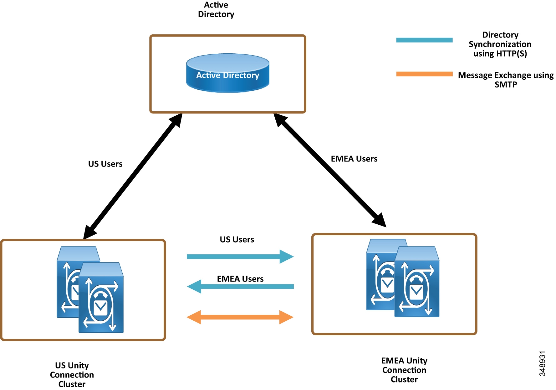
In HTTPS networking, Unity Connection clusters are joined together using a hub-and-spoke topology. In this topology, all the directory information among the spokes is shared through the hub that connects the spokes. The number of Unity Connection locations that can be connected in an HTTPS network and the maximum number of users in HTTPS networking depend on the deployed OVA template. For more information on the maximum number of supported locations and maximum directory size, refer to the information on directory object limits in the latest version of the System Requirements for Cisco Unity Connection, available at
https://www.cisco.com/c/en/us/support/unified-communications/unity-connection/products-installation-guides-list.html
In HTTPS networking, the directory replication is accomplished by means of a Feeder service and a Reader service running on each location in the network. The Reader service periodically polls the remote location for any directory changes since the last poll interval. The Feeder service checks the change tracking database for directory changes and responds to poll requests with the necessary information.
In the HTTPS networking, when the publisher server of a cluster location is up and running, it is responsible for the synchronization of directory information. However, if the publisher server is down, the subscriber server takes the role of synchronizing directory information.
Depending upon the server of a cluster (publisher or subscriber) with which the directory synchronization is being performed, the directory synchronization can be either of the following types:
- Standard — Specifies that the directory synchronization is done by the publisher server with the connected locations.
- Alert — Specifies that the publisher server is unreachable and the subscriber server is responsible for providing directory information to the connected locations. However, the subscriber server has the directory information stored that was last synchronized with the publisher server when it was running.
In the event of a publisher failure, directory synchronization occurs in the Alert mode. During the Alert mode, the connected nodes in the HTTPS network have limited access to directory synchronization with the subscriber. The limited access means that the connected nodes can fetch only the directory information that was last synchronized with the publisher when it was running. When the publisher comes up, the nodes that are directly connected to the publisher synchronize the updated directory information through the publisher. Therefore, the key benefit of the Alert mode is that the connected nodes remain synchronized with the subscriber server even when the publisher is down.
The clusters that are networked together are directly accessible through TCP/IP port 25 (SMTP).In addition, both locations must be able to route to each other via HTTPS on port 8444.
For the purposes of this deployment documentation, HTTPS internetworking is configured between the US and EMEA Unity Connection clusters. Table 5-20 shows the server node information of both clusters that are joined using HTTPS networking.
|
|
|
|
||
|---|---|---|---|---|
|
|
|
|
|
|
To set up HTTPS networking between two Unity Connection clusters, perform the following tasks.
Check the Display Name and SMTP Domain of Each Unity Connection Server
Create the HTTPS Network Between Unity Connection Clusters
- To create an HTTPS network of Unity Connection servers, start by linking two clusters together by creating an HTTPS link and then ensuring that the subscribers of each cluster are added for the SMTP Access.
- On each Unity Connection publisher, add a new HTTPS link. Table 5-21 shows the HTTPS Link settings.
Configure SMTP Access for Cluster Subscriber Servers
In an HTTPS network that includes a Unity Connection cluster server pair, you can join only the publisher server of the pair to the network. In order for all locations in the network to communicate directly with the cluster subscriber server node when the subscriber is the primary server, all network locations should be configured to allow SMTP connections from the subscriber server.
In this example we are adding the EMEA subscriber to the SMTP configuration of the US publisher, as well as adding the US subscriber to the EMEA publisher SMTP configuration.
- In the US cluster on the US publisher, add the EMEA subscriber to the SMTP configuration (System Settings). In the Edit menu, select Search IP Address Access List. On the New IP Address page, enter the IP address of an EMEA subscriber server (< IP_Address_EMEA_CUC2 >). Ensure that the Allow Connection option is selected.
- Repeat the above steps on the EMEA cluster publisher, emea-cuc1.ent-pa.com, to add the US cluster subscriber IP address.
Replication Between the Locations
After creating the HTTPS network, verify that the complete database is replicated between the two locations added to network. When initial replication begins, it can take a few minutes to a few hours for the data to be fully replicated between all locations, depending on the size of your directory.
Open the HTTP(S) Link created in the above step, and check the following values:
Indicates the time stamp of the last time the local reader service attempted to poll the remote location feeder service for directory changes on the remote locations, regardless of whether a response was received.
Indicates the time stamp of the last time the local reader service encountered an error while attempting to poll the remote location feeder service. If the value of this field is 0, or if the Time of Last Synchronization value is later than the Time of Last Error value, replication is likely to be progressing without problems.
Indicates the number of users that the local Unity Connection location has synchronized from the remote location.
Add Remote Location Partition to Local Unity Connection CSS
When you initially set up a network between locations, users that are provisioned on the US cluster will not able to send voice messages to users on the EMEA cluster because the users in each location are in separate partitions and separate user search spaces that do not contain the partitions of users in the other locations.
- Edit the us-cuc1 calling search space (CSS) configured for the US Unity Connection server to include the EMEA location Unity Connection server partition emea-cuc1.
- Edit the emea-cuc1 CSS configured for the EMEA Unity Connection server to include the US location Unity Connection server partition us-cuc1.
Related Documentation
For additional information about voice messaging and Cisco Unity Connection, refer to the latest version of the following documents, available at the links provided below:
https://www.cisco.com/c/en/us/support/unified-communications/unity-connection/products-implementation-design-guides-list.html
https://www.cisco.com/c/en/us/support/unified-communications/unity-connection/products-maintenance-guides-list.html
https://www.cisco.com/c/en/us/support/unified-communications/unity-connection/products-maintenance-guides-list.html
 Feedback