Cisco DRaaS with Zerto Virtual Replication and VMware Virtual SAN Book
Bias-Free Language
The documentation set for this product strives to use bias-free language. For the purposes of this documentation set, bias-free is defined as language that does not imply discrimination based on age, disability, gender, racial identity, ethnic identity, sexual orientation, socioeconomic status, and intersectionality. Exceptions may be present in the documentation due to language that is hardcoded in the user interfaces of the product software, language used based on RFP documentation, or language that is used by a referenced third-party product. Learn more about how Cisco is using Inclusive Language.
- Updated:
- July 28, 2014
Chapter: DRaaS Application
- Zerto Virtual Replication Architecture
DRaaS Application
Several options exist in the choice of technology for the implementation of DRaaS, which is associated with varying levels of cost, complexity, and operational models. A summary of technology options for the implementation is presented in Figure 3-1.
Figure 3-1 Many Approaches to DRaaS

The hypervisor-based replication technology is one of the recommended implementations for Cisco's DRaaS System architecture. It is delivered in partnership with The Zerto Virtual Replication (ZVR) product offering because of the value and the differentiation ZVR provides delivering DR services for virtual-to-virtual (V2V) workloads.
Layer 2 Extensions and IP mobility using Overlay Transport Virtualization (OTV) and Locator/ID Separation Protocol (LISP) to support partial failovers and active-active scenarios are part of the VMDC Virtual Services Architecture (VSA) 1.0 solution. The solution presents heterogeneous, storage, and infrastructure-agnostic data replication capabilities for the creation and offer of DR solution offerings. The system offers continuous data protection (CDP)-based recovery with the ability to roll back to any point in time. The system provides guaranteed application consistency for most of the widely-used industry applications.
Zerto Virtual Replication Architecture
ZVR and workflow orchestration is a powerful DR solution for organizations that have virtualized environments. ZVR functions at the hypervisor layer, replicating the changes made on the servers at the production site to one or more recovery locations, including the CSP sites. ZVR provides robust workflow orchestration of the failover, migration, and failback operations while allowing complete failover testing that is not disruptive to the production environment. For the CSP, ZVR is an important technological advance that opens up a whole new set of DRaaS and in-the-cloud cost-effective service offerings.
Since ZVR is "VM-aware," it is possible to select only the VMs that need to be protected which in turn saves storage space at the secondary site as well as network bandwidth between sites. Further, ZVR does not require similar storage between sites, which allows for cheaper or repurposed storage to be used at the target site. The CSP site can be added as a target site as well since ZVR has no hardware dependencies. This presents compelling options to the customer in using one solution for protecting all of their servers, including lower-tier VM protection to any site, public or private.
For the CSP, having the same data protection platform that the customer is using simplifies and accelerates the sales and on-boarding process by removing the barriers to adoption. Additionally, ZVR is natively multi-tenant, so the internal deployment on the CSP infrastructure is non-disruptive.
ZVR allows for very granular protection since the VMware VM VMDKs are being replicated. For application protection, multiple VMs can be put into application affinity groupings called Virtual Protection Groups (VPGs). Virtual machines that are in a VPG have write-order fidelity, which means that the recovery points-in-time are consistent across all the VMs in the VPG.
A hypervisor-based replication solution aligns with the capabilities of the hypervisor, extending the flexibility, agility and benefits of virtualization to BC/DR.
In summary, Zerto Virtual Replication:
- Removes deployment barriers with a storage agnostic solution that installs seamlessly into the existing infrastructure.
- Supports multiple VMware vSphere versions, mixed VMware licensing levels, VMware vCloud environments.
- Provides a centralized DR management solution, regardless of the VM placement.
- Is completely virtual-aware so the customer can make changes to the production environment without impacting existing BC/DR processes.
- Enables hybrid cloud services. VM portability between private and public clouds is simple with very low recovery times when using ZVR.
- Provides the technical infrastructure for secure and segmented multi-tenant DR access
However, providing DR services is different from providing other cloud-based services:
- In a DRaaS scenario, the customer may manage and have complete control over the production data, or the CSP may provide a partial or complete managed service. In either case, the CSP must ensure the availability of the data and adapt as the customer’s infrastructure changes.
- When customers leverage an ICDR service, the CSP manages the production and DR sites. The VMs are typically replicated from one CSP data center to another CSP data center as a managed service or as managed co-located data centers. The customers have the ability to interact with their applications as if they were locally hosted.
What is consistent in both scenarios is that the customers have deeper ties to their data when compared to other cloud-based services because they often need to access the actual VMs running the applications.
CSPs are challenged to provide a multi-tenant service that bridges together and connects dissimilar data centers from customers to the CSP's cloud as well as having customer-initiated tests and failovers.
Helping the CSP Provide a Dynamic DR Platform
At the core of the Zerto design philosophy is to simplify DR while providing powerful replication, recovery, and testing with no impact on the environment. ZVR makes VMs more geographically portable and simplifies the technology behind the DR that the CSP provides to customers. With ZVR 3.0, Zerto improves the management experience by adding multi-tenant cloud management and customer-initiated enablement technologies with Zerto Cloud Manager (ZCM) and the Zerto Self Service Portal (ZSSP).
The ZCM allows the CSP to provide resources from multiple CSP data centers and define service level templates called Service Profiles to multiple customers via a unified administrative interface. From the customer perspective, the CSP provides the ZSSP, which is a web-based portal that enables self-initiated provisioning, testing, and failover capability through a private, intuitive administration interface.
By making DR easier to provide and consume, Zerto helps the CSP reach the enterprise IT Manager better by offering DR options that were previously unfeasible or cost-prohibitive. The CSP can offer services ranging from fully managed DR to providing DR for only a portion of the Enterprise’s VMs where a hybrid cloud-based DR approach is a better solution.
Zerto helps drive new service offering innovation for the CSPs. For example, a growing service offering from CSPs using ZVR is “reverse DR.” This configuration uses the CSP’s cloud as the primary site while the customer’s site or sites serve as the DR targets. This is an attractive option to many customers because it allows the customer to use less or older hardware for their DR locally and leverage the power and availability of the CSP’s equipment.
Zerto Cloud Manager: Enablement for Cloud DR Resource Management
CSPs regularly host the same customer in multiple global locations. ZVR's unique architecture can easily support replication between sites around the world.
While ZVR creates an advantage for CSPs by enabling them to replicate to and from anywhere, it introduces the need for a centralized interface that consolidates information from multiple sites to make management and reporting easier and more accurate.
Zerto has created the Zerto Cloud Manager (ZCM) to deliver centralized management for DR in the cloud. The ZCM consolidates and streamlines resource information into a single interface to make multi-site, multi-tenant, dynamic DR environments easier to manage. The automated consolidation and reporting on cloud usage increases the confidence of customers that they will be billed accurately on their infrastructure usage.
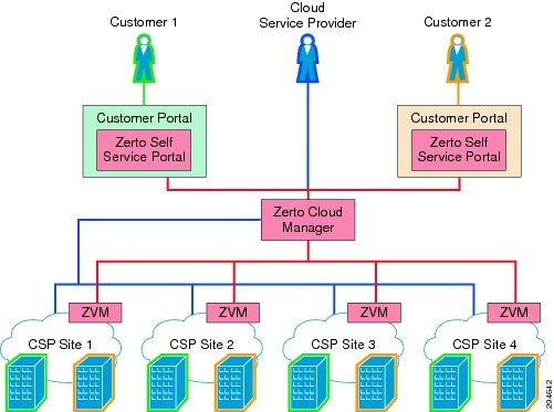
As shown in Figure 3-2, the ZCM manages all of the information from the ZVM at each location in a central user interface.
Figure 3-2 An Example ZVR Deployment

ZCM is the "manager of managers," which is to say the ZCM interfaces with each site’s ZVM and allows the CSP administrator to have a single point of management. The administrator can view all of the individual site configurations and statuses, create and manage VPGs, conduct failover tests, migrations or actual failovers, and generate reports, alerts and billing information.
Service Profiles
As self-service customers grow to be a larger percentage of the CSP customer base, streamlined workflows and repeatable processes are needed to better meet customer expectations and keep CSP costs low.
Service Profiles give policy-based management and automation capabilities to CSPs to ensure SLAs and service offerings are always consistent. Service Profiles reduce the administrative effort of the CSP by providing a customer-initiated capability to protect VMs.
Service Profiles enable a CSP to define structured service offerings with specific SLA parameters, including RPO, journal maximum size, history, and service level expectations. New Service Profiles can be added to a pool of existing Service Profiles that the CSP has predefined. These profiles make self-service much simpler, decreasing the learning curve for CSP customers, who simply select a profile from a drop-down list. Customers are also able to choose or update the Service Profile selection at the VPG creation stage if they have the proper permissions.
As seen in Figure 3-3, a CSP may have three Service Profiles: Gold, Silver and Bronze. These Service Profiles are created in the ZCM and can be presented to multi-tenant customers. Service Profiles are controlled with permissions set by the CSP to limit customer profile selections to only predefined profiles, or create their own custom Service Profile.

Enablement for Cloud DR Resource Consumption: Zerto Self Service Portal
DR requires an infrastructure level of integration between CSPs and customers. Depending on the service level requirements, cloud-based DR presents a unique challenge for CSPs because it often requires a two-way interaction that most cloud providers are not prepared to provide.
When customers want a fully managed service, the CSP manages both sides of the DR as their own administrative resources can readily meet that need. However, when customers want a more interactive hybrid DR service that requires that both CSP and the customer have infrastructure level administrative access, the CSP often has to create a customized DR portal to meet the customer access needs.
To help CSPs overcome the challenge of having to develop a custom portal just for DR, Zerto created the Zerto Self Service Portal (ZSSP). The ZSSP gives customers streamlined access to administrative functions and provides CSPs a way to quickly deploy a complete cloud-based DR solution.
The ZSSP is designed to be an out-of-the-box DR portal solution. Having a fully functioning browser-based service portal available without a great deal of coding or scripting enables CSPs to quickly introduce DR as part of their existing portal or as a stand-alone portal. CSPs are able to quickly offer a robust DR service for faster ROI.
ZSSP Features
The ZSSP incorporates all of the APIs that were commonly requested by CSPs in production. Providing these APIs enables the CSP to rapidly roll out a more automated client experience.
ZCM enables the ZSSP by providing CSPs with the capability to offer a single point-of-view portal for their customers to view the status of their SLAs and manage the DR or migration status of their VMs regardless of the actual location of those VMs.
Figure 3-4 ZVM and the Zerto Self Service Portal
Being browser-based, the ZSSP enables unprecedented management of business continuity and disaster recovery. Administrators can monitor service levels, perform non-disruptive tests, and perform actual failovers from many different devices, including many mobile devices.
Storage
Storage is the main component in the Cisco DRaaS 2.0 system. Proper storage sizing and deployment is critical for delivering an optimized service to customers. The following storage efficiency feature is recommended at the CSP recovery site:
- Thin Provisioning —Thin provisioning is a good method for optimizing utilization of available storage. It relies on an on-demand allocation of blocks of data versus the traditional method of allocating all the blocks up front. This method eliminates all the unused space, which increases utilization efficiencies. The best practice is to enable thin provisioning at the storage level or at the hypervisor level to avoid management challenges.

Note![]() In the DRaaS 2.0 system, because Zerto is capable of creating VMs using thin provisioning in the cloud, it is recommended to implement thin provisioning at the hypervisor layer. In the DRaaS 2.0 system, because Zerto is capable of creating VMs using thin provisioning in the cloud, it is recommended to implement thin provisioning at the hypervisor layer.
In the DRaaS 2.0 system, because Zerto is capable of creating VMs using thin provisioning in the cloud, it is recommended to implement thin provisioning at the hypervisor layer. In the DRaaS 2.0 system, because Zerto is capable of creating VMs using thin provisioning in the cloud, it is recommended to implement thin provisioning at the hypervisor layer.
The following storage efficiency features are specific to EMC VNX when using vBlock as the Integrated Compute Stack (ICS) architecture:
- FAST Cache —EMC FAST Cache technology is an extension of existing DRAM cache in that it allocates certain flash drives to serve as FAST Cache. The benefit is that hotter data from applications running inside the VM will be copied to FAST Cache. Hence, these applications will see improved response time and throughput since the I/O is now serviced from flash drives. In DRaaS environments, FAST Cache is useful during concurrent customer site failovers and during the onboarding of new customers. In general, FAST Cache should be used in cases where storage performance needs to improve immediately for I/O that is burst-prone.
- FAST VP —Data has a lifecycle and as data progresses through this lifecycle, it experiences varying levels of activity. When data is created, typically it is accessed very frequently. As it ages, it is accessed less often. This is often referred to as data being temporal in nature. EMC FAST VP is a simple and elegant solution for dynamically matching storage requirements with changes in the frequency of data access. FAST VP segregates disk drives into the following three tiers: Extreme Performance Tier (flash drives); Performance Tier (Serial Attached SCSI (SAS) drives for EMC VNX); and Capacity Tier (Near-Line SAS (NL-SAS) drives for EMC VNX platforms).
–![]() You can use FAST VP to reduce TCO and/or to increase performance. A target workload requiring a large number of Performance Tier drives can be serviced with a mix of tiers and a much lower drive count. In some cases, nearly two-thirds reduction in drive count is achieved. In other cases, performance throughput can double simply by adding no more than 10% of a pool's total capacity in flash drives.
You can use FAST VP to reduce TCO and/or to increase performance. A target workload requiring a large number of Performance Tier drives can be serviced with a mix of tiers and a much lower drive count. In some cases, nearly two-thirds reduction in drive count is achieved. In other cases, performance throughput can double simply by adding no more than 10% of a pool's total capacity in flash drives.
–![]() FAST VP and FAST Cache can be used together to improve storage system performance.
FAST VP and FAST Cache can be used together to improve storage system performance.
–![]() Customers with a limited number of flash drives can create FAST Cache and storage pools consisting of performance and capacity drives. For performance, FAST Cache will provide immediate benefits for any burst-prone data, while FAST VP will move warmer data to performance drives and colder data to capacity drives.
Customers with a limited number of flash drives can create FAST Cache and storage pools consisting of performance and capacity drives. For performance, FAST Cache will provide immediate benefits for any burst-prone data, while FAST VP will move warmer data to performance drives and colder data to capacity drives.
–![]() FAST Cache is storage system-aware so that storage system resources are not wasted by unnecessarily copying data to FAST Cache if it already exists on flash drives. If FAST VP moves a slice of data to the Extreme Performance Tier, FAST Cache will not promote that slice into FAST Cache - even if it has met the FAST Cache criteria for promotion.
FAST Cache is storage system-aware so that storage system resources are not wasted by unnecessarily copying data to FAST Cache if it already exists on flash drives. If FAST VP moves a slice of data to the Extreme Performance Tier, FAST Cache will not promote that slice into FAST Cache - even if it has met the FAST Cache criteria for promotion.
–![]() When initially deploying flash drives in a storage system, the recommendation is to use them for FAST Cache. FAST Cache will track I/Os smaller than 128 KB and requires multiple cache hits to 64 KB chunks. This will initiate promotions from performance or capacity drives to Flash Cache and, as a result, I/O profiles that do not meet this criteria are better served by flash drives in a pool or RAID group.
When initially deploying flash drives in a storage system, the recommendation is to use them for FAST Cache. FAST Cache will track I/Os smaller than 128 KB and requires multiple cache hits to 64 KB chunks. This will initiate promotions from performance or capacity drives to Flash Cache and, as a result, I/O profiles that do not meet this criteria are better served by flash drives in a pool or RAID group.
The following storage efficiency features are specific to NetApp when using FlexPod as an integrated stack within VMDC:
- Flash Cache —NetApp Flash Cache speeds access to data through real-time intelligent caching of recently read user data and NetApp metadata. It is effective for random read-intensive workloads, including database, e-mail, and file services. The combination of intelligent caching and NetApp data storage efficiency technologies enables the virtual storage tier, which promotes hot data to performance media in real time without moving the data, allowing you to scale performance and capacity while achieving the highest level of storage efficiency in the industry.
- Flash Pool —Flash Pool is a technology that allows flash technology in the form of solid-state disks (SSDs) and traditional hard disk drives (HDDs) to be combined to form a single Data onTap aggregate. When SSD and HDD technologies are combined in a Data onTap aggregate, the NetApp storage system takes advantage of the latency and throughput benefits of SSD while maintaining the mass storage capacity of the HDD.
–![]() A Flash Pool is built from a Data onTap aggregate in a two-step process. Essentially, it is the addition of SSDs into an aggregate that provides a high-bandwidth, low-latency location that is capable of caching random reads and random overwrites.
A Flash Pool is built from a Data onTap aggregate in a two-step process. Essentially, it is the addition of SSDs into an aggregate that provides a high-bandwidth, low-latency location that is capable of caching random reads and random overwrites.
Note This feature does not require a license and works with any NetApp SSDs and a consistent type of HDD per Flash Pool. That is, SSD and SAS performance drives can be combined to make a Flash Pool or SSD and SATA capacity drives can be combined to make a Flash Pool. You cannot combine SSD, SAS, and SATA into a single Flash Pool.
–![]() As a key component of the NetApp Virtual Storage Tier, Flash Pool offers a real-time, highly efficient implementation of automated storage tiering. Fine-grain promotion of hot data elements, combined with data deduplication and thin cloning, enables optimal performance and optimal use of flash storage technology.
As a key component of the NetApp Virtual Storage Tier, Flash Pool offers a real-time, highly efficient implementation of automated storage tiering. Fine-grain promotion of hot data elements, combined with data deduplication and thin cloning, enables optimal performance and optimal use of flash storage technology.
- De-duplication —NetApp de-duplication is an integral part of the NetApp Data onTap operating environment and the WAFL file system, which manages all data on NetApp storage systems. De-duplication works "behind the scenes," regardless of what applications you run or how you access data, and its overhead is low.
–![]() NetApp de-duplication is a key component of NetApp's storage efficiency technologies, which enable users to store the maximum amount of data for the lowest possible cost.
NetApp de-duplication is a key component of NetApp's storage efficiency technologies, which enable users to store the maximum amount of data for the lowest possible cost.
–![]() NetApp de-duplication is a process that can be triggered when a threshold is reached, scheduled to run when it is most convenient, or run as part of an application. It will remove duplicate blocks in a volume or LUN.
NetApp de-duplication is a process that can be triggered when a threshold is reached, scheduled to run when it is most convenient, or run as part of an application. It will remove duplicate blocks in a volume or LUN.
In summary, steady-state storage considerations include:
- FAST VP from EMC.
- Flash Pool from NetApp.
- During the steady state replication, the target storage will have the information about the I/ O characteristics and data blocks.
- NetApp Flash Cache and EMC FAST Cache are useful in dealing with unpredicted I/O needs that can be observed during the recovery of multiple customer environments during a disaster.
- NetApp Flash Pool and EMC FAST VP are useful efficiency features that help the CSP to use storage space more efficiently during a steady-state replication scenario. Warmer data gets moved to the faster drives and cold data gets moved to the capacity disks automatically.
- NetApp de-duplication and storage thin provisioning reduces the total storage footprint required to support customer workloads.
Compression
To ensure efficient use of the WAN between sites, replication data sent from one site to another should be compressed before it is sent. This helps to reduce the WAN bandwidth required for data replication. This can be accomplished by using a dedicated external device or by using technologies that are incorporated in the DRaaS 2.0 solution, such as the integrated compression capability available in ZVR.
ZVR can perform data compression, which is a good option for customers who do not want to have a dedicated device for this functionality. It is an ideal choice for customers who have fewer servers being protected.
However, there are advantages of going with an external dedicated compression appliance, including:
- Better handling of data compression and management as the dedicated hardware will be used only for this functionality. This offloads the processing load from DR component that does the compression.
- Compression of non-DR related traffic, optimizing the overall WAN bandwidth usage.
- Easier troubleshooting of contention issues.
Dedicated Cisco WAN Optimization Products
Network links and WAN circuits are sometimes characterized by high latency, packet loss, and limited capacity. WAN optimization devices can be used to maximize the amount of replicated data that can be transmitted over a link.
A WAN Optimization Controller (WOC) is an appliance that can be placed in-line or out-of-path to reduce and optimize the data that is to be transmitted over the WAN. These devices are designed to help mitigate the effects of packet loss, network congestion, and latency while reducing the overall amount of data transmitted over the network. In general, the technologies utilized in accomplishing this are TCP acceleration, data deduplication, and compression. WAN and data optimization can occur at varying layers of the OSI stack, whether they be at the Network and Transport Layers, the Session, Presentation, and Application layers, or just to the ata (payload) itself.
Cisco Wide Area Application Services (WAAS) devices can be used for data optimization. The WAAS system consists of a set of devices called Wide Area Application Engines (WAE) that work together to optimize TCP traffic over the network. Cisco WAAS uses a variety of transport flow optimization (TFO) features to optimize TCP traffic intercepted by the WAAS devices. TFO protects communicating devices from negative WAN conditions, such as bandwidth constraints, packet loss, congestion, and retransmission. TFO includes optimization features such as compression, windows scaling, Selective ACK, increased buffering, BIC TCP, and TCP Initial Window Size Maximization.
Cisco WAAS uses Data Redundancy Elimination (DRE) and LZ compression technologies to help reduce the size of data transmitted over the WAN. These compression technologies reduce the size of transmitted data by removing redundant information before sending a shortened data stream over the WAN. By reducing the amount of transferred data, WAAS compression reduces network utilization and application response times.
When a WAE uses compression to optimize TCP traffic, it replaces repeated data in the stream with a much shorter reference and then sends the shortened data stream out across the WAN. The receiving WAE uses its local redundancy library to reconstruct the data stream before passing it along to the destination. The WAAS compression scheme is based on a shared cache architecture in which each WAE involved in compression and decompression shares the same redundancy library. When the cache that stores the redundancy library on a WAE becomes full, WAAS uses a FIFO algorithm (first in, first out) to discard old data and make room for new.
Note![]() For more information about Cisco WAAS technologies, visit: For more information about Cisco WAAS technologies, visit: http://www.cisco.com/go/waas.
For more information about Cisco WAAS technologies, visit: For more information about Cisco WAAS technologies, visit: http://www.cisco.com/go/waas.
Zerto Virtual Replication
Compression within ZVR is enabled by a simple checkbox when configuring the VPG. Zerto and Cisco tested the Zerto compression capability and the results exceeded an average of 50% bandwidth savings between sites, depending on the compressibility of the data. Each VRA that operates on each host in the VMware cluster is responsible for the compression. Having this distributed model of compression minimizes the CPU and RAM impact on the host system.
Encryption
Encryption of data-in-transit and data-at-rest is the best method of enforcing the security and privacy of data, regardless of where it resides. Data-in-transit encryption is necessary to keep the data secure while in transit. The network connection between sites must be secure and the data must be protected. The use of IPsec or SSL to encrypt WAN connections ensures that no visibility occurs at the packet level if any of the datagrams are intercepted in transit.
ZVR does not support encryption natively. Encryption of data-in-transit between the sites can be accomplished using an external device, such as the Cisco Adaptive Security Appliance (ASA). The Cisco ASA 55xx Series is a purpose-built platform that combines superior security and VPN services for enterprise applications. The Cisco ASA 55xx Series enables customization for specific deployment environments and options, with special product editions for secure remote access (SSL/IPSec VPN).
The Cisco ASA 55xx Series SSL/IPsec VPN Edition uses network-aware IPsec site-to-site VPN capabilities. This allows customers to extend their networks securely across low-cost Internet connections to the CSP site.
Encryption of data-at-rest can add further security to the storage environment on the CSP's data center. Any external key manager can be used in conjunction with SAN fabrics and storage arrays to secure data-at-rest.
In the control plane, ZVR uses HTTPS to encrypt communications with other components in the system, including:
ZVR Disaster Recovery Workflow
Zerto Virtual Replication provides a number of operations to recover VMs at the peer site, as shown in the following sections.
The Move Operation
Use the Move operation to migrate protected VMs from the protected (source) site to the recovery (target) site in a planned migration.
When you perform a planned migration of the VMs to the recovery site, Zerto Virtual Replication assumes that both sites are healthy and that you planned to relocate the VMs in an orderly fashion without data loss.
The Move operation follows these basic steps:
Step 1![]() Gracefully shut down the protected VMs to ensure data integrity. If the machines cannot be gracefully shut down, for example, when VMware Tools is not available, an Administrator can manually shut down the machines before starting the Move operation or specify as part of the operation a forced power off the VMs. If the machines cannot be gracefully shut down automatically and are not manually shut down and the Move operation is not set to forcibly power them off, the Move operation stops and ZVR rolls back the VMs to their original status.
Gracefully shut down the protected VMs to ensure data integrity. If the machines cannot be gracefully shut down, for example, when VMware Tools is not available, an Administrator can manually shut down the machines before starting the Move operation or specify as part of the operation a forced power off the VMs. If the machines cannot be gracefully shut down automatically and are not manually shut down and the Move operation is not set to forcibly power them off, the Move operation stops and ZVR rolls back the VMs to their original status.
Step 2![]() Insert a clean checkpoint. This avoids potential data-loss since the VMs are not powered on and the new checkpoint is created after all I/Os have been written to disk.
Insert a clean checkpoint. This avoids potential data-loss since the VMs are not powered on and the new checkpoint is created after all I/Os have been written to disk.
Step 3![]() Transfer to the recovery site all the latest changes that are still being queued to pass to the recovery site, including the new checkpoint.
Transfer to the recovery site all the latest changes that are still being queued to pass to the recovery site, including the new checkpoint.
Step 4![]() Create the VMs at the remote site in the production network and attach each VM to its relevant disks, based on the checkpoint inserted in Step 2.
Create the VMs at the remote site in the production network and attach each VM to its relevant disks, based on the checkpoint inserted in Step 2.
Step 5![]() Power on the VMs in the recovery site making them available to the user. If applicable, the boot order defined in the VPG settings is used to power on the machines in a specified order.
Power on the VMs in the recovery site making them available to the user. If applicable, the boot order defined in the VPG settings is used to power on the machines in a specified order.
Step 6![]() Run basic tests on the machines to ensure their validity to the specified checkpoint. Depending on the commit/rollback policy that was specified for the operation after testing, either the operation is committed—finalizing the Move—or rolled back, aborting the operation. You can also configure the move operation to automatically commit the move, without testing.
Run basic tests on the machines to ensure their validity to the specified checkpoint. Depending on the commit/rollback policy that was specified for the operation after testing, either the operation is committed—finalizing the Move—or rolled back, aborting the operation. You can also configure the move operation to automatically commit the move, without testing.
Step 7![]() The source VMs are removed from the inventory.
The source VMs are removed from the inventory.
Step 8![]() The data from the journal is promoted to the machines. The machines can be used during the promotion and ZVR ensures that the user sees the latest image, even if this is partially data from the journal. That is, when accessing the migrated VM, ZVR can present data both from the disks and from the journal, to ensure that information is current.
The data from the journal is promoted to the machines. The machines can be used during the promotion and ZVR ensures that the user sees the latest image, even if this is partially data from the journal. That is, when accessing the migrated VM, ZVR can present data both from the disks and from the journal, to ensure that information is current.
If reverse replication was specified —the disks used by the VMs in the source site are used for the reverse protection. A Delta Sync is performed to make sure that the two copies—the new target site disks and the original source site disks—are consistent.
If reverse replication was not specified —the VPG definition is saved but the state is left at “Needs Configuration” and the disks used by the VMs in the source site are deleted. Thus, if reverse protection is not set the original disks are not available and a full synchronization will be required.
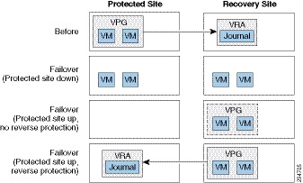
Figure 3-5 shows the positioning of the VMs before and after the completion of a Move operation.

Note![]() The Move operation without reverse protection does not remove the VPG definition but leaves it in a “Needs Configuration” state. The Move operation without reverse protection does not remove the VPG definition but leaves it in a “Needs Configuration” state.
The Move operation without reverse protection does not remove the VPG definition but leaves it in a “Needs Configuration” state. The Move operation without reverse protection does not remove the VPG definition but leaves it in a “Needs Configuration” state.
The Failover Operation
Use the Failover operation following a disaster to recover protected VMs to the recovery site. A failover assumes that connectivity between the sites might be down, and thus the source VMs and disks are not removed, as they are in a planned Move operation.
When you set up a failover, you always specify a checkpoint to which you want to recover the VMs. When you select a checkpoint—either the latest auto-generated checkpoint, an earlier checkpoint, or a user-defined checkpoint—ZVR makes sure that VMs at the remote site are recovered to this specified point-in-time.
Note![]() To identify the checkpoint to use, you can perform a number of consecutive test failovers, each to a different checkpoint until the desired checkpoint for recovery is determined. To identify the checkpoint to use, you can perform a number of consecutive test failovers, each to a different checkpoint until the desired checkpoint for recovery is determined.
To identify the checkpoint to use, you can perform a number of consecutive test failovers, each to a different checkpoint until the desired checkpoint for recovery is determined. To identify the checkpoint to use, you can perform a number of consecutive test failovers, each to a different checkpoint until the desired checkpoint for recovery is determined.
The Failover operation has the following basic steps:
Step 1![]() Create the VMs at the remote site in the production network and attach each VM to its relevant disks, configured to the checkpoint specified for the recovery.
Create the VMs at the remote site in the production network and attach each VM to its relevant disks, configured to the checkpoint specified for the recovery.
Note![]() The source VMs are not touched since the assumption is that the production site is down. The source VMs are not touched since the assumption is that the production site is down.
The source VMs are not touched since the assumption is that the production site is down. The source VMs are not touched since the assumption is that the production site is down.
Step 2![]() Power on the VMs, making them available to the user. If applicable, the boot order, defined in the VPG settings to power on the machines in a specified order, is used.
Power on the VMs, making them available to the user. If applicable, the boot order, defined in the VPG settings to power on the machines in a specified order, is used.
Step 3![]() Run basic tests on the machines to ensure their validity to the specified checkpoint. Depending on the commit/rollback policy that was specified for the operation after testing, either the operation is committed—finalizing the Move—or rolled back, aborting the operation. You can also configure the failover operation to automatically commit the move, without testing.
Run basic tests on the machines to ensure their validity to the specified checkpoint. Depending on the commit/rollback policy that was specified for the operation after testing, either the operation is committed—finalizing the Move—or rolled back, aborting the operation. You can also configure the failover operation to automatically commit the move, without testing.
Step 4![]() If the source site is still available, for example after a partial disaster, and reverse protection is possible and specified for the failover operation, the source VMs are powered off and removed from the inventory. The disks used by the VMs in the source site are then used for the reverse protection. A Delta Sync is performed to make sure that the two copies, the new target site disks and the original source site disks, are consistent.
If the source site is still available, for example after a partial disaster, and reverse protection is possible and specified for the failover operation, the source VMs are powered off and removed from the inventory. The disks used by the VMs in the source site are then used for the reverse protection. A Delta Sync is performed to make sure that the two copies, the new target site disks and the original source site disks, are consistent.
Note![]() If reverse protection is not possible, or reverse protection is configured to not use the original disks, the source site VMs are not powered off and are instead removed. In the latter case, if possible, the VMs should be shut down manually before starting the failover. If reverse protection is not possible, or reverse protection is configured to not use the original disks, the source site VMs are not powered off and are instead removed. In the latter case, if possible, the VMs should be shut down manually before starting the failover.
If reverse protection is not possible, or reverse protection is configured to not use the original disks, the source site VMs are not powered off and are instead removed. In the latter case, if possible, the VMs should be shut down manually before starting the failover. If reverse protection is not possible, or reverse protection is configured to not use the original disks, the source site VMs are not powered off and are instead removed. In the latter case, if possible, the VMs should be shut down manually before starting the failover.
Step 5![]() The data from the journal is promoted to the machines. The machines can be used during the promotion and ZVR ensures that the user sees the latest image, even if this is partially data from the journal.
The data from the journal is promoted to the machines. The machines can be used during the promotion and ZVR ensures that the user sees the latest image, even if this is partially data from the journal.
Failback after the Original Site is Operational
To perform a failback to the source site, the VPG that is now protecting the VMs on the target site has to be configured. A Delta Sync is then performed with the disks in the source site. Once the VPG is in a protecting state the VMs can be moved back to the source site.
Figure 3-6 shows the positioning of the VMs before and after the completion of a Failover operation
Figure 3-6 ZVR Failback Operation
Note![]() The Failover operation without reverse protection does not remove the VPG definition but leaves it in a “Needs Configuration” state. The Failover operation without reverse protection does not remove the VPG definition but leaves it in a “Needs Configuration” state.
The Failover operation without reverse protection does not remove the VPG definition but leaves it in a “Needs Configuration” state. The Failover operation without reverse protection does not remove the VPG definition but leaves it in a “Needs Configuration” state.
Disaster Recovery Workflow
Figure 3-7 shows the disaster recovery testing workflow.
Figure 3-7 Testing Disaster Recovery Workflow

During any live test, it is recommended not to maintain two working versions of the same VMs. Thus, the first step in any test, except for a Failover Test or Clone, is to make sure that the production virtual machines are shut down before starting to test recovered machines. During a Zerto Virtual Replication Move operation, the first step Zerto Virtual Replication performs is to shut down the protected machines, to ensure data integrity. However, a Zerto Virtual Replication Failover operation assumes that the production VMs are no longer accessible (the total site disaster scenario) and does not attempt by default to shut them down at the beginning of the operation.
In a live test using a failover operation, you have to specify that you want to shut down the VMs to be tested at the beginning of the test to prevent potential split-brain situations where two instances of the same applications are live at the same time.
If you want to perform a live DR test that includes a simulated disaster you can simulate the disaster by, for example, disconnecting the network between the two sites. In this type of test, once the disaster is simulated a Move operation cannot be used, since it requires both sites to be healthy, while a Failover operation can be used.
Best Practices
The following best practices are recommended:
- Prepare an administrator account for the machine where ZVR is installed.
- Install ZVR on a dedicated VM with a dedicated administrator account and with VMware High Availability (HA) enabled and no other applications installed on the VM. If other applications are installed, the Zerto Virtual Manager service must receive enough resources and HA must remain enabled.
- Install a VRA on every host in a cluster so that if protected VMs are moved from one host to another, there is always a VRA to protect the moved VMs. When protecting a vApp, you must install a VRA on every host in the cluster on both the protected and recovery sites and ensure that DRS is enabled for the clusters.
- Install VRAs using static IP addresses and not DHCP.
- Set any antivirus software not to scan the folder where ZVR is installed.
- Ensure the clocks on the machines where ZVR is installed are synchronized using NTP.
Note![]() There is much more information available regarding Zerto operation, implementation, and monitoring in the Cisco DRaaS 2.0 Implementation Guide, available at: There is much more information available regarding Zerto operation, implementation, and monitoring in the Cisco DRaaS 2.0 Implementation Guide, available at: http://www.cisco.com/go/draas.
There is much more information available regarding Zerto operation, implementation, and monitoring in the Cisco DRaaS 2.0 Implementation Guide, available at: There is much more information available regarding Zerto operation, implementation, and monitoring in the Cisco DRaaS 2.0 Implementation Guide, available at: http://www.cisco.com/go/draas.
 Feedback