- Preface
- Product Overview
- Command-Line Interfaces
- Configuring the Switch for the First Time
- Administering the Switch
- Configuring the Cisco IOS In Service Software Upgrade Process
- Configuring Interfaces
- Checking Port Status and Connectivity
- Configuring Supervisor Engine Redundancy Using RPR and SSO
- Configuring Cisco NSF with SSO Supervisor Engine Redundancy
- Environmental Monitoring and Power Management
- Configuring Power over Ethernet
- Configuring the Catalyst 4500 Series Switch with Cisco Network Assistant
- Configuring VLANs, VTP, and VMPS
- Configuring IP Unnumbered Interface
- Configuring Layer 2 Ethernet Interfaces
- Configuring SmartPort Macros
- Configuring STP and MST
- Configuring Flex Links and Flex Links+
- Configuring Resilient Ethernet Protocol
- Configuring Optional STP Features
- Configuring EtherChannel
- Configuring IGMP Snooping and Filtering
- Configuring IPv6 MLD Snooping
- Configuring 802.1Q and Layer 2 Protocol Tunneling
- Configuring CDP
- Configuring LLDP
- Configuring UDLD
- Configuring Unidirectional Ethernet
- Configuring Layer 3 Interfaces
- Configuring Cisco Express Forwarding
- Configuring Unicast Reverse Path Forwarding
- Configuring IP Multicast
- Configuring Policy-Based Routing
- Configuring VRF-lite
- Configuring Quality of Service
- Configuring Voice Interfaces
- Configuring Private VLANs
- Configuring 802.1X Port-Based Authentication
- Configuring Port Security
- Configuring Control Plane Policing
- Configuring DHCP Snooping, IP Source Guard, and IPSG for Static Hosts
- Configuring Dynamic ARP Inspection
- Configuring Network Security with ACLs
- Port Unicast and Multicast Flood Blocking
- Configuring Storm Control
- Configuring SPAN and RSPAN
- Configuring System Message Logging
- Configuring SNMP
- Configuring NetFlow
- Configuring Cisco IP SLA
- Configuring RMON
- Performing Diagnostics
- Configuring WCCP Version 2 Services
- ROM Monitor
- Configuring MIB Support
- Configuring CFM and OAM
- Configuring Y.1731
- Acronym
- Index
Configuring Flex Links and the MAC Address-Table Move Update Feature

Note ![]() LAN Base image does not support Flex Links.
LAN Base image does not support Flex Links.
Flex Links provide a fast and simplified Layer 2 Link redundancy mechanism. This chapter describes how to configure Flex Links on the Catalyst 4500 series switch. It also describes how to configure the MAC address-table move update feature(MMU), also referred to as the Flex Links bidirectional fast convergence feature.
Note ![]() For complete syntax and usage information for the switch commands used in this chapter, first look at the Cisco Catalyst 4500 Series Switch Command Reference and related publications at this location:
For complete syntax and usage information for the switch commands used in this chapter, first look at the Cisco Catalyst 4500 Series Switch Command Reference and related publications at this location:
http://www.cisco.com/en/US/products//hw/switches/ps4324/index.html
If the command is not found inthe Catalyst 4500 Command Reference, it will be found in the larger Cisco IOS library. Refer to the Cisco IOS Command Reference and related publications at this location:
http://www.cisco.com/en/US/products/ps6350/index.html
The chapter consists of these sections:
•![]() Flex Links and the MAC Address-Table Move Update
Flex Links and the MAC Address-Table Move Update
•![]() Configuring Flex Links and the MAC Address-Table Move Update
Configuring Flex Links and the MAC Address-Table Move Update
•![]() Monitoring Flex Links and the MAC Address-Table Move Update
Monitoring Flex Links and the MAC Address-Table Move Update
Flex Links and the MAC Address-Table Move Update
This section contains this information:
•![]() VLAN Flex Link Load Balancing and Support
VLAN Flex Link Load Balancing and Support
•![]() MAC Address-Table Move Update
MAC Address-Table Move Update
Flex Links
Flex Links are a pair of Layer 2 interfaces (switch ports or port channels) where one interface is configured to act as a backup to the other. Users can disable STP and still retain basic link redundancy. Flex Links are typically configured in service provider or enterprise networks where customers do not want to run STP on some interfaces.
You configure Flex Links on one Layer 2 interface (the active link) by assigning another Layer 2 interface as the Flex Link or backup link. When one of the links is up and forwarding traffic, the other link is in standby mode, ready to begin forwarding traffic if the other link fails. At any given time, only one of the interfaces is in the forwarding state and forwarding traffic. If the primary link fails, the standby link starts forwarding traffic. When the active link reactivates, it enters standby mode and does not forward traffic. STP is disabled on Flex Link interfaces.
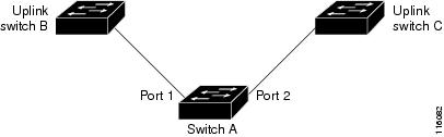
In Figure 18-1, ports 1 and 2 on switch A are connected to uplink switches B and C. Because they are configured as Flex Links, only one of the interfaces is forwarding traffic; the other is in standby mode. If port 1 is the active link, it begins forwarding traffic between port 1 and switch B; the link between port 2 (the backup link) and switch C is not forwarding traffic. If port 1 shuts down, port 2 activates and starts forwarding traffic to switch C. When port 1 reactivates, it enters standby mode and does not forward traffic; port 2 continues forwarding traffic.
You can also choose to configure a preemption mechanism, specifying the preferred port for forwarding traffic. In Figure 18-1, for example, you can configure the Flex Link pair with preemption mode so that after port 1 reactivates in the scenario, and it has greater bandwidth than port 2, port 1 begins forwarding after a duration equal to the preemption delay; and port 2 becomes the standby. You do this by entering the interface configuration switchport backup interface preemption mode bandwidth and switchport backup interface preemption delay commands.
Figure 18-1 Flex Links Configuration Example
If a primary (forwarding) link shuts down, a trap notifies the network management stations. If the standby link shuts down, a trap notifies the users.
Flex Links are supported only on Layer 2 ports and port channels. Because Flex Links fully operate with PVLANs t they may be configured on a pair of PVLAN trunks.
VLAN Flex Link Load Balancing and Support
VLAN Flex Link load-balancing allows you to configure a Flex Link pair so that both ports simultaneously forward the traffic for mutually exclusive VLANs. For example, if Flex Link ports are configured for 1-100 VLANs, the traffic of the first 50 VLANs can be forwarded on one port and the rest on the other port. If one of the ports fail, the other active port forwards all the traffic. When the failed port reactivates, it resumes forwarding traffic in the preferred VLANs. This way, apart from providing the redundancy, this Flex Link pair can be used for load balancing. Also, Flex Link VLAN load-balancing does not impose any restrictions on uplink switches (Figure 18-2).
Figure 18-2 VLAN Flex Links Load Balancing Configuration Example

Note ![]() A static MAC address must point to a Flex Link interface that is forwarding for given VLAN. For example, if a backup interface is forwarding VLAN X, then a static MAC address in VLAN X must point to the backup interface. Misconfiguration might cause unexpected results.
A static MAC address must point to a Flex Link interface that is forwarding for given VLAN. For example, if a backup interface is forwarding VLAN X, then a static MAC address in VLAN X must point to the backup interface. Misconfiguration might cause unexpected results.
MAC Address-Table Move Update
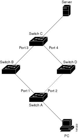
In Figure 18-3, ports 1 and 2 on switch A are connected to uplink switches B and D through a Flex Linkpair. Port 1 is forwarding traffic, and port 2 is in the blocking state. Traffic from the PC to the server is forwarded from port 1 to port 3. The MAC address of the PC has been learnt on port 3 of switch C. Traffic from the server to the PC is forwarded from port 3 to port 1.
If port 1 shuts down, port 2 starts forwarding traffic. If there is no traffic from PC to the server after failover to port 2, switch C does not learn MAC address of the PC on port 4. As a result, switch C keeps forwarding traffic from the server to the PC out of port 3. There is traffic loss from server to PC because port 1 is down. This problem is alleviated by sending out a dummy multicast packet with source MAC address of the PC over port 2. Switch C learns the PC MAC address on port 4 and start forwarding traffic from server to the PC out of port 4. One dummy multicast packet is sent out for every MAC address. This is the default flexlink behavior. The MAC address-table Move Update (MMU) feature may be enabled to further expedite downstream convergence. MMUs are special packets that carry multiple MAC addresses. Switch A is configured to transmit these packets and switches B, C and D are configured to receive such packets. If MMU transmit is enabled on Switch A, MAC move updates are transmitted before dummy multicast packets over port 2. Switch D processes and floods MMUs over to Switch C. Switch C processes these packets, and moves the MAC addresses contained within the packets from port 3 to port 4. Because one packet carries multiple MAC addresses, downstream convergence is faster.
Figure 18-3 MAC Address-Table Move Update Example
Flex Link Failover Actions
Following are important actions that are performed when a Flex Link primary fails:
•![]() Detect Link failure.
Detect Link failure.
•![]() Move static unicast MAC addresses configured on the primary link to the standby link.
Move static unicast MAC addresses configured on the primary link to the standby link.
•![]() Move dynamic unicast MAC addresses learned on the primary link to the standby link.
Move dynamic unicast MAC addresses learned on the primary link to the standby link.
•![]() Move the standby link to a forwarding state.
Move the standby link to a forwarding state.
•![]() Transmit MAC Address-table Move updates over new active, if Mac move update transmit is enabled.
Transmit MAC Address-table Move updates over new active, if Mac move update transmit is enabled.
•![]() Transmit dummy multicast packets over new active interface.
Transmit dummy multicast packets over new active interface.
Note ![]() Local administrative shut down or a link becoming forwarding again due to preemption is not considered a link failure. The action in such cases is to flush dynamic hosts and not move them.
Local administrative shut down or a link becoming forwarding again due to preemption is not considered a link failure. The action in such cases is to flush dynamic hosts and not move them.
Static MAC address move on a Flex Link failover. Static MAC addresses configured on a Flex Link member interface are moved over to the backup, provided it fails. Static MAC addresses configured on a Flex Link member interface are restored when it becomes forwarding again.
Note ![]() The sh mac address-table command always shows static MAC addresses as associated with the interface on which it was configured even if it may have been moved to the standby link because of a Flex Link failover.
The sh mac address-table command always shows static MAC addresses as associated with the interface on which it was configured even if it may have been moved to the standby link because of a Flex Link failover.
Configuring Flex Links and the
MAC Address-Table Move Update
These sections contains the following information:
•![]() Configuring VLAN Load Balancing on Flex Links
Configuring VLAN Load Balancing on Flex Links
•![]() Configuring the MAC Address-Table Move Update Feature
Configuring the MAC Address-Table Move Update Feature
Default Configuration
Observe the following points:
•![]() Flex Links are not configured on any interface.
Flex Links are not configured on any interface.
•![]() Preemption mode is off.
Preemption mode is off.
•![]() If preemption is enabled, preemption delay is 35 seconds.
If preemption is enabled, preemption delay is 35 seconds.
•![]() The MAC address-table move update feature is disabled.
The MAC address-table move update feature is disabled.
Configuration Guidelines
Follow these guidelines to configure Flex Links:
•![]() You can configure only one Flex Link backup link for any active link, and it must be a different interface from the active interface.
You can configure only one Flex Link backup link for any active link, and it must be a different interface from the active interface.
•![]() An interface can belong to only one Flex Link pair. An interface can be a backup link for only one active link, but an active link cannot belong to another Flex Link pair.
An interface can belong to only one Flex Link pair. An interface can be a backup link for only one active link, but an active link cannot belong to another Flex Link pair.
•![]() Neither of the links can be a port that belongs to an EtherChannel. However, you can configure two port channels (EtherChannel logical interfaces) as Flex Links. Moreover, you can configure a port channel and a physical interface as Flex Links, with either the port channel or the physical interface as the active link.
Neither of the links can be a port that belongs to an EtherChannel. However, you can configure two port channels (EtherChannel logical interfaces) as Flex Links. Moreover, you can configure a port channel and a physical interface as Flex Links, with either the port channel or the physical interface as the active link.
•![]() The types (Fast Ethernet, Gigabit Ethernet, or port channel) of the backup link and the active link can differ. However, you should configure both Flex Links with similar characteristics so that there are no loops or changes in behavior if the standby link begins to forward traffic.
The types (Fast Ethernet, Gigabit Ethernet, or port channel) of the backup link and the active link can differ. However, you should configure both Flex Links with similar characteristics so that there are no loops or changes in behavior if the standby link begins to forward traffic.
•![]() STP is disabled on Flex Link ports. A Flex Link port does not participate in STP, even if the VLANs present on the port are configured for STP. When STP is not enabled, ensure that there are no loops in the configured topology.
STP is disabled on Flex Link ports. A Flex Link port does not participate in STP, even if the VLANs present on the port are configured for STP. When STP is not enabled, ensure that there are no loops in the configured topology.
•![]() Configure any static MAC addresses on a Flex Link member interface after enabling Flex Link.
Configure any static MAC addresses on a Flex Link member interface after enabling Flex Link.
Follow these guidelines to configure VLAN load balancing on the Flex Links feature:
•![]() For Flex Link VLAN load balancing, you must choose the preferred VLANs on the backup interface.
For Flex Link VLAN load balancing, you must choose the preferred VLANs on the backup interface.
•![]() You cannot configure preemption and VLAN load balancing for the same Flex Links pair.
You cannot configure preemption and VLAN load balancing for the same Flex Links pair.
Follow these guidelines to configure the MAC address-table move update feature:
•![]() Enable mac address-table move transmit on the switch with flexlinks configured to send MAC address-table move updates.
Enable mac address-table move transmit on the switch with flexlinks configured to send MAC address-table move updates.
•![]() Enable mac address-table move receive on all upstream switches to process MAC address-table move updates.
Enable mac address-table move receive on all upstream switches to process MAC address-table move updates.
Configuring Flex Links
To configure a pair of Flex Links, follow these steps:
To disable a Flex Link backup interface, enter the no switchport backup interface interface-id interface configuration command.
This example shows how to configure an interface with a backup interface and to verify the configuration:
Switch# configure terminal
Switch(conf)# interface fastethernet1/1
Switch(conf-if)# switchport backup interface fastethernet1/2
Switch(conf-if)# end
Switch# show interface switchport backup
Switch Backup Interface Pairs:
Active Interface Backup Interface State
------------------------------------------------------------------------
FastEthernet1/1 FastEthernet1/2 Active Up/Backup Standby
FastEthernet1/3 FastEthernet1/4 Active Up/Backup Standby
Port-channel1 GigabitEthernet1/1 Active Up/Backup Standby
To configure a preemption scheme for a pair of Flex Links, follow these steps:
To remove a preemption scheme, enter the no switchport backup interface interface-id preemption mode interface configuration command. To reset the delay time to the default, enter the
no switchport backup interface interface-id preemption delay interface configuration command.
This example shows how to configure preemption mode as bandwidth for a backup interface pair and to verify the configuration:
Switch# configure terminal
Switch(conf)# interface gigabitethernet1/0/1
Switch(conf-if)# switchport backup interface gigabitethernet1/2
Switch(conf-if)# switchport backup interface gigabitethernet1/2 preemption mode forced
Switch(conf-if)# switchport backup interface gigabitethernet1/2 preemption delay 50
Switch(conf-if)# end
Switch# show interface switchport backup detail
Active Interface Backup Interface State
------------------------------------------------------------------------
GigabitEthernet1/21 GigabitEthernet1/2 Active Down/Backup Down
Interface Pair : Gi1/21, Gi1/2
Preemption Mode : forced
Preemption Delay : 50 seconds
Bandwidth : 10000 Kbit (Gi1/1), 10000 Kbit (Gi1/2)
Mac Address Move Update Vlan : auto
<output truncated>
Configuring VLAN Load Balancing on Flex Links
To configure VLAN load balancing on Flex Links, follow these steps:
To disable the VLAN load balancing feature, enter the
no switchport backup interface interface-id prefer vlan vlan-range interface configuration command.
In this example, VLANs 1 to 50, 60, and 100 to 120 are configured on the switch:
Switch(config)# interface fastethernet 1/6
Switch(config-if)# switchport backup interface fastethernet 1/0/8 prefer vlan 60,100-120
When both interfaces are up, Fast Ethernet port1/0/8 forwards traffic for VLANs 60 and 100 to 120 and Fast Ethernet port 1/0/6 forwards traffic for VLANs 1 to 50.
Switch# show interfaces switchport backup
Switch Backup Interface Pairs:
Active Interface Backup Interface State
------------------------------------------------------------------------
FastEthernet1/6 FastEthernet1/8 Active Up/Backup Standby
Vlans Preferred on Active Interface: 1-50
Vlans Preferred on Backup Interface: 60, 100-120
When a Flex Link interface shuts down, VLANs preferred on this interface are moved to the peer interface of the Flex Link pair. In this example, if interface 1/6 shuts down, interface 1/8 carries all VLANs of the Flex Link pair.
Switch# show interfaces switchport backup
Switch Backup Interface Pairs:
Active Interface Backup Interface State
------------------------------------------------------------------------
FastEthernet1/6 FastEthernet1/8 Active Down/Backup VLB all
Vlans Preferred on Active Interface: 1-50
Vlans Preferred on Backup Interface: 60, 100-120
When a Flex Link interface becomes active, VLANs preferred on this interface are blocked on the peer interface and moved to the forwarding state on the interface that has just come up. In this example, if interface Fast Ethernet port 1/6 becomes active, VLANs preferred on this interface are blocked on the peer interface Fast Ethernet port 1/8 and forwarded on Fast Ethernet port 1/6.
Switch# show interfaces switchport backup
Switch Backup Interface Pairs:
Active Interface Backup Interface State
------------------------------------------------------------------------
FastEthernet1/6 FastEthernet1/8 Active VLB cfg/Backup VLB cfg
Vlans Preferred on Active Interface: 1-50
Vlans Preferred on Backup Interface: 60, 100-120
Switch# show interfaces switchport backup detail
Switch Backup Interface Pairs:
Active Interface Backup Interface State
------------------------------------------------------------------------
FastEthernet1/6 FastEthernet1/8 Active VLB cfg/Backup VLB cfg
Vlans Preferred on Active Interface: 1-50
Vlans Preferred on Backup Interface: 60, 100-120
Preemption Mode : off
Bandwidth : 10000 Kbit (Fa1/6), 100000 Kbit (Fa1/8)
Mac Address Move Update Vlan : auto
Configuring the MAC Address-Table Move Update Feature
This section contains this information:
•![]() Configuring a switch to send MAC address-table move updates
Configuring a switch to send MAC address-table move updates
•![]() Configuring a switch to receive MAC address-table move updates
Configuring a switch to receive MAC address-table move updates
To configure an access switch to send MAC address-table move updates, follow these steps:
To disable the MAC address-table move update feature on the access switch, enter the
no mac address-table move update transmit interface configuration command. To display the MAC address-table move update information, enter the show mac address-table move update command.
This example shows how to configure an access switch to send MAC address-table move update messages and to verify the configuration:
Switch# configure terminal
Switch(conf)# interface fastethernet1/1
Switch(conf-if)# switchport backup interface fastethernet1/0/2 mmu primary vlan 2
Switch(conf-if)# end
Switch(conf)# mac address-table move update transmit
Switch(conf)# end
Switch# show mac-address-table move update
Switch-ID : 01d0.2bfc.3180
Dst mac-address : 0180.c200.0010
Vlans/Macs supported : 4096/55000
Default/Current settings: Rcv Off/Off, Xmt Off/On
Max packets per min : Rcv 100, Xmt 120
Rcv packet count : 0
Rcv conforming packet count : 0
Rcv invalid packet count : 0
Rcv packet count this min : 0
Rcv threshold exceed count : 0
Rcv last sequence# this min : 0
Rcv last interface : None
Rcv last src-mac-address : 0000.0000.0000
Rcv last switch-ID : 0000.0000.0000
Xmt packet count : 0
Xmt packet count this min : 0
Xmt threshold exceed count : 0
Xmt pak buf unavail cnt : 0
Xmt last interface : fa1/2
To configure a switch to receive and process MAC address-table move update messages, do the following:
To disable the MAC address-table move update feature on the access switch, enter the
no mac address-table move update receive configuration command. To display the MAC address-table move update information, enter the show mac address-table move update command.
This example shows how to configure a switch to receive and process MAC address-table move update messages:
Switch# configure terminal
Switch(conf)# mac address-table move update receive
Switch(conf)# end
Monitoring Flex Links and
the MAC Address-Table Move Update
Table 18-1 shows the commands for monitoring the Flex Links configuration and the MAC address-table move update information.
 Feedback