Software-Defined Access Wireless

Information about Software-Defined Access Wireless

The Enterprise Fabric provides end-to-end enterprise-wide segmentation, flexible subnet addressing, and controller-based networking with uniform enterprise-wide policy and mobility. It moves the enterprise network from current VLAN-centric architecture to a user group-based enterprise architecture, with flexible Layer 2 extensions within and across sites.

Enterprise fabric is a network topology where traffic is passed through inter-connected switches, while providing the abstraction of a single Layer 2 or Layer 3 device. This provides seamless connectivity, with policy application and enforcement at the edge of the fabric. Fabric uses IP overlay, which makes the network appear as a single virtual entity without using clustering technologies.

The following definitions are used for fabric nodes:

  • Enterprise Fabric: A network topology where traffic is passed through inter-connected switches, while providing the abstraction of a single Layer 2 or Layer 3 device.

  • Fabric Domain: An independent operation part of the network. It is administered independent of other fabric domains.

  • End Points: Hosts or devices that connect to the fabric edge node are known as end points (EPs). They directly connect to the fabric edge node or through a Layer 2 network.

The following figure shows the components of a typical SD-Access Wireless. It consists of Fabric Border Nodes (BN), Fabric Edge Nodes (EN), Wireless Controller, Cisco Catalyst Center, and Host Tracking Database (HDB).

Figure 1. Software-Defined Access Wireless

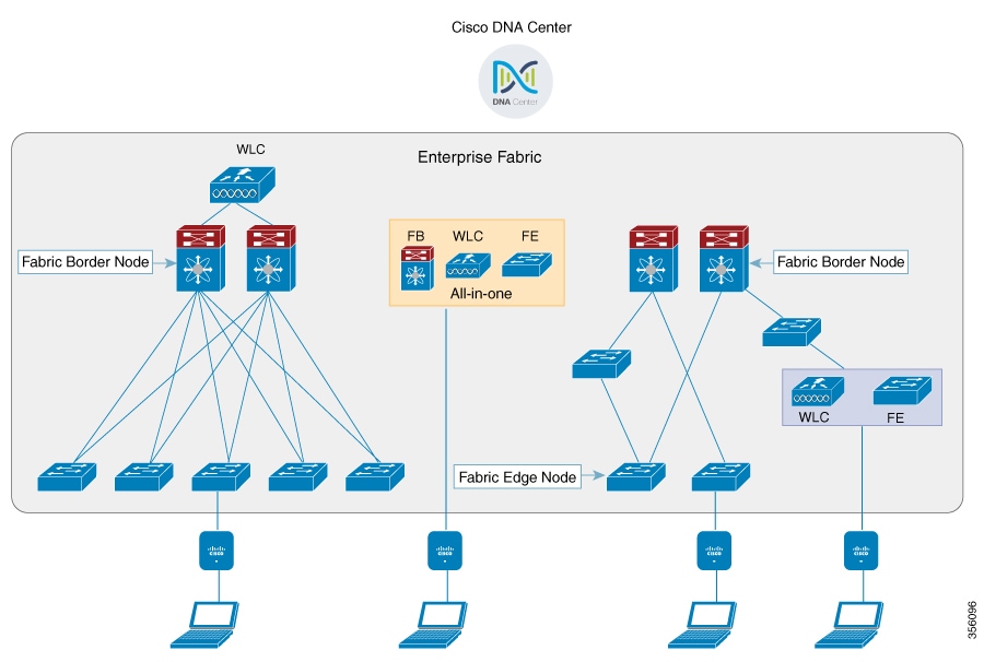
The figure covers the following deployment topologies:

  • All-in-one Fabric—When we have all Fabric Edge, Fabric Border, Control-Plane and controller functionality enabled on a Cat 9K switch.

    This topology is depicted in the mid part of the figure.

  • Split topology—When we have Fabric Border, or Control Plane, or controller on a Cat 9K switch with separate Fabric Edge. This topology is depicted in the left-most part of the figure.

  • Co-located Fabric Edge and Controller—When we have Fabric Edge and controller on a Cat 9K switch. This topology is depicted in the right-most part of the figure.

Cisco Catalyst Center: Is an open, software-driven architecture built on a set of design principles with the objective of configuring and managing Cisco Catalyst 9800 Series Wireless Controllers.

Control Plane: This database allows the network to determine the location of a device or user. When the EP ID of a host is learnt, other end points can query the database about the location of the host. The flexibility of tracking subnets helps in summarization across domains and improves the scalability of the database.

Fabric Border Node (Proxy Egress Tunnel Router [PxTR or PITR/PETR] in LISP): These nodes connect traditional Layer 3 networks or different fabric domains to the enterprise fabric domain. If there are multiple fabric domains, these nodes connect a fabric domain to one or more fabric domains, which could be of the same or different type. These nodes are responsible for translation of context from one fabric domain to another. When the encapsulation is the same across different fabric domains, the translation of fabric context is generally 1:1. The fabric control planes of two domains exchange reachability and policy information through this device.

Fabric Edge Nodes (Egress Tunnel Router [ETR] or Ingress Tunnel Router [ITR] in LISP): These nodes are responsible for admitting, encapsulating or decapsulating, and forwarding of traffic from the EPs. They lie at the perimeter of the fabric and are the first points of attachment of the policy. EPs could be directly or indirectly attached to a fabric edge node using an intermediate Layer 2 network that lies outside the fabric domain. Traditional Layer 2 networks, wireless access points, or end hosts are connected to fabric edge nodes.

Wireless Controller: The controller provides AP image and configuration management, client session management and mobility. Additionally, it registers the mac address of wireless clients in the host tracking database at the time of client join, as well as updates the location at the time of client roam.

Access Points: AP applies all the wireless media specific features. For example, radio and SSID policies, webauth punt, peer-to-peer blocking, and so on. It establishes CAPWAP control and data tunnel to controller. It converts 802.11 data traffic from wireless clients to 802.3 and sends it to the access switch with VXLAN encapsulation.

The SDA allows to simplify:

  • Addressing in wireless networks

  • Mobility in wireless networks

  • Guest access and move towards multi-tenancy

  • Leverage Sub-net extension (stretched subnet) in wireless network

  • Provide consistent wireless policies


Note


Role co-location between wireless controller and fabric edge is supported.


Platform Support

Table 1. Supported Platforms for Software-Defined Access Wireless

Platforms

Support

Catalyst 9300

Yes

Catalyst 9400

Yes

Catalyst 9500H

Yes

Cisco Catalyst 9800 Series Wireless Controller for Cloud

Yes

Cisco Catalyst 9800-40 Series Wireless Controller

Yes

Cisco Catalyst 9800-80 Series Wireless Controller

Yes

Table 2. Multi-Instance Support

Multi-instance

Support

Multiple LISP sessions

Yes

Emulated database support

Yes

Client roaming between WNCd instances

Yes

Table 3. Feature Support

Feature

Support

Inter-WLC roam for IRCM

Only L2 mobility is supported as VLAN is stretched across the fabric.

DNS-IPv4-ACL

  • ACLs are enforced at AP.

  • Controller needs to push the DNS-ACL information to AP.

IPv6 ACL for clients

Yes. Open, 802.11x, WebAuth, PSK WLANs, IPv6 address visibility are also supported.

Location tracking/Hyperlocation

Yes

Multicast Video-Stream (IPv4)

Yes

Smart Licensing

Yes

Table 4. Outdoor Access Points Support

AP

Support

1542

Yes

1560

Yes

Information About SD-Access Wireless Mesh Inter Fabric Edge Switch Roaming Protection

When a Mesh AP (MAP) finds a Root AP (RAP) or other MAP with better adjacency, it roams to that RAP or MAP. However, a MAP cannot roam to another MAP or RAP connected to a different fabric edge switch due to wireless client connectivity loss. The reason being the VXLAN tunnels of the wireless client cannot be moved to another fabric edge switch.

However, if the current MAP link is much worse than the link to RAP or MAP connected to a different fabric edge switch, then the MAP roams and restart its CAPWAP tunnel.

Thus, all the MAPs connected to the MAP restarts the CAPWAP tunnels as well. This allows the wireless clients to connect again and creates wireless client VXLAN tunnels in the fabric edge.


Note


The criteria for a MAP roaming to a RAP or MAP connected to a different fabric edge switch are the same as the mesh preferred parent. They are:

  • If the current link SNR is worse than 12 dB and there is another better link. (Or)

  • If the current link SNR is worse than 20 dB and there is another link with 20% or better SNR.

The mesh daisy chain roaming is not supported in RAP or MAP connected to different fabric edge switches.


SDA IPv6 Underlay Support

This feature provides a wireless SDA IPv6 underlay support to enable IPv6-based communications in a fabric site. IPv6 is used to establish LISP connections between the controller and map server as well as between the map server and Fabric Edge. IPv6 underlay is also used to construct a VXLAN tunnel between the Fabric Edge and the AP.

The feature implementation is as follows:

  • Catalyst 9800 Controller:

    • The controller manages IPv6-based LISP sessions to the map server

    • Encodes, decodes, and processes LISP messages through IPv6 TCP/UDP sockets.)

    • Communicates RLOC IPv6 address to the AP for VXLAN creation and client tunnel mapping

  • Fabric Edge:

    • Processes map notification from map server

    • Creates IPv6 VXLAN tunnel

    • Maps client to IPv6 VXLAN tunnel

    • Encapsulates and decapsulates client traffic into and out of VXLAN tunnel

  • Access Points:

    • Processes fabric TLV from the controller

    • Creates IPv6 VXLAN tunnel

    • Encapsulates and decapsulates client traffic into and out of VXLAN tunnel

The following figure shows the feature architecture:


Note


For AP to join controller using IPv6 address, ensure that you configure the preferred mode in AP profile as IPv6.


Restrictions

Embedded wireless controller (EWC) on Catalyst 9k switches is not supported.

Configuring SD-Access Wireless

  • To enable SD-Access wireless globally, you need to run the wireless fabric configuration command.

  • During SD-Access Wireless provisioning, ensure that L2-VNID value is unique.

Configuring Default Map Server (GUI)

Procedure


Step 1

Click Configuration > Wireless Plus > Fabric > Fabric Configuration.

Step 2

In the Map Server section, specify the IP address and preshared key details for Server 1.

Step 3

Optionally, you can specify the IP address and preshared key details for Server 2.

Step 4

Click Apply.


Configuring Default Map Server (CLI)

Follow the procedure given below to configure default map server:

Procedure

  Command or Action Purpose

Step 1

configure terminal

Example:

Device# configure terminal

Enters the global configuration mode.

Step 2

wireless fabric control-plane map-server-name

Example:

Device(config)# wireless fabric control-plane map-server-name

Configures the default map server.

Here, map-server-name defines a pair of map servers.

Step 3

ip address ip-address key user_password reenter_password

Example:

Device(config-wireless-cp)# ip address 200.0.0.0 key user-password user-password

Configures IP address for the default map server.

Step 4

end

Example:

Device(config-wireless-cp)# end

Returns to privileged EXEC mode. Alternatively, you can also press Ctrl-Z to exit global configuration mode.

Configuring SD-Access Wireless Profile (GUI)

Procedure


Step 1

Choose Configuration > Wireless > Fabric.

Step 2

On the Fabric page, click the Profiles tab and click Add.

Step 3

In the Add New Profile window that is displayed, specify the following parameters:

  • Profile name

  • Description

  • L2 VNID; valid range is between 0 and 16777215

  • SGT tag; valid range is between 2 and 65519

Step 4

Click Save & Apply to Device.


Configuring SD-Access Wireless Profile (CLI)

Follow the procedure given below to configure SD-Access wireless profile:

Procedure

  Command or Action Purpose

Step 1

configure terminal

Example:

Device# configure terminal

Enters the global configuration mode.

Step 2

wireless profile fabric fabric-profile-name

Example:

Device(config)# wireless profile fabric fabric-profile-name

Configures the SD-Access wireless profile parameters.

Step 3

sgt-tag sgt

Example:

Device(config-wireless-fabric)# sgt-tag 2

Configures SGT tag.

Here, sgt refers to the sgt tag value. The valid range is from 2-65519. The default value is 0.

Step 4

client-l2-vnid client-l2-vnid

Example:

Device(config-wireless-fabric)# client-l2-vnid client-l2-vnid

Configures client L2-VNID.

Here, client-l2-vnid refers to the client L2-VNID value. The valid range is from 0-16777215.

Step 5

end

Example:

Device(config-wireless-fabric)# end

Returns to privileged EXEC mode. Alternatively, you can also press Ctrl-Z to exit global configuration mode.

Configuring Map Server in Site Tag (GUI)

Before you begin

Ensure that you have configured a control plane at the time of configuring Wireless Fabric.

Procedure


Step 1

Choose Configuration > Tags & Profiles > Tags.

Step 2

On the Manage Tags page, click the Site tab.

Step 3

Click the name of the site tag.

Step 4

In the Edit Site Tag window, choose the Fabric control plane name from the Control Plane Name drop-down list.

Step 5

Save the configuration.


Configuring Map Server in Site Tag (CLI)

Follow the procedure given below to configure map server in site tag:

Procedure

  Command or Action Purpose

Step 1

configure terminal

Example:

Device# configure terminal

Enters the global configuration mode.

Step 2

wireless tag site site-tag

Example:

Device(config)# wireless tag site default-site-tag

Configures site tag.

Here, site-tag refers to the site tag name.

Step 3

fabric control-plane map-server-name

Example:

Device(config-site-tag)# fabric control-plane map-server-name

Configures fabric control plane details.

Here, map-server-name refers to the fabric control plane name associated with the site tag.

Step 4

end

Example:

Device(config-site-tag)# end

Returns to privileged EXEC mode. Alternatively, you can also press Ctrl-Z to exit global configuration mode.

Configuring Map Server per L2-VNID (GUI)

Procedure


Step 1

Choose Configuration > Wireless > Fabric.

Step 2

On the Fabric Configuration page in the Fabric VNID Mapping section, click Add.

Step 3

In the Add Client and AP VNID window, specify a name for the Fabric, L2 VNID value (valid range is from 0 to 4294967295), control plane name.

Step 4

Save the configuration.


Configuring Map Server per L2-VNID (CLI)

Follow the procedure given below to configure map server in site tag:

Procedure

  Command or Action Purpose

Step 1

configure terminal

Example:

Device# configure terminal

Enters the global configuration mode.

Step 2

wireless fabric name name l2-vnid l2-vnid-value l3-vnid l3-vnid-value ip network-ip subnet-mask control-plane-name control-plane-name

Example:

Device(config)# wireless fabric name fabric_name l2-vnid 2 l3-vnid 2 ip 122.220.234.0 255.255.0.0 control-plane-name sample-control-plane

Configures the map server to the VNID map table.

  • name refers to the fabric name.

  • l2-vnid-value refers to the L2 VNID value. The valid range is from 0 to 16777215.

  • L3-vnid-value refers to the L3 VNID value. The valid range is from 0 to 16777215.

  • control-plane-name refers to the control plane name.

Step 3

end

Example:

Device(config)# end

Returns to privileged EXEC mode.

Verifying SD-Access Wireless

You can verify the SD-Access wireless configurations using the following commands:

Table 5. Commands for Verifying SD-Access Wireless
Commands Description
show wireless fabric summary

Displays the fabric status.

show wireless fabric vnid mapping

Displays all the VNID mapping details.

show wireless profile fabric detailed fabric_profile_name

Displays the details of a given fabric profile name.

show ap name AP_name config general

Displays the general details of the Cisco AP.

show wireless client mac MAC_addr detail

Displays the detailed information for a client by MAC address.

show wireless tag site detailed site_tag

Displays the detailed parameters for a site tag.