Control and Provisioning of Wireless Access Points

Overview

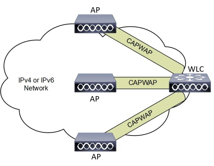
CAPWAP is an IEEE standard protocol that enables a wireless LAN controller to manage multiple APs and Wireless LAN Controllers (WLCs) to exchange control and data plane information over a secure communication tunnel.

CAPWAP only operates in Layer 3 and requires IP addresses to be present on both the APs and WLC. CAPWAP establishes tunnels on the UDP ports 5246 and 5247 for IPv4 and IPv6 respectively. It adds extra security with Datagram Transport Layer Security (DTLS) encryption.

DTLS serves as a protocol ensuring security between the AP and WLC, facilitating encrypted communication to prevent eavesdropping or tampering in potential man-in-the-middle attacks.

By default, DTLS secures the control channel for CAPWAP, encrypting all CAPWAP management and control traffic between the AP and WLC.

The data channel remains disabled by default, leaving client data moving between an AP and WLC unencrypted. Enabling CAPWAP data encryption is discretionary, and it necessitates the installation of a DTLS license on the WLC before activation on an AP.

If an AP does not support DTLS data encryption, DTLS is enabled only for the control plane, and a DTLS session for the data plane is not established

If an AP supports Data DTLS, it enables data DTLS after receiving the new configuration from the controller. The AP performs a DTLS handshake on port 5247 and after successfully establishing the DTLS session. All the data traffic (from the AP to the controller and the controller to the AP) is encrypted.

CAPWAP allows administrators to manage the entire wireless network from a central location. The IW9165E use the Internet Engineering Task Force (IETF) standard CAPWAP to communicate between the controller and other AP on the network.

Figure 1. CAPWAP APs connected to a WLC

Certificate Provisioning on Lightweight Access Point

In order to provision a new certificate on LAP, while in CAPWAP mode, the LAP must be able to get the new signed X.509 certificate. In order to do this, it sends a certRequest to the controller, which acts as a CA proxy and helps obtain the certRequest signed by the CA for the LAP.

The certReq and the certResponses are sent to the LAP with the LWAPP payloads.

Both the LSC CA and the LAP device certificates are installed in the LAP, and the system reboots automatically. The next time when the system comes up, because it is configured to use LSCs, the AP sends the LSC device certificate to the controller as part of the JOIN Request. As part of the JOIN Response, the controller sends the new device certificate and also validates the inbound LAP certificate with the new CA root certificate.

What to Do Next

To configure, authorize, and manage certificate enrollment with the existing PKI infrastructure for controller and AP, you need to use the LSC provisioning functionality.

Understanding CAPWAP Connectivity On AP

When CAPWAP is enabled, the first function is to initiate a discovery phase. Wireless APs search for a controller by sending discovery request messages. Upon receiving a discovery request, the controller replies with a discovery response. At this point, the two devices establish a secure connection using the Datagram Transport Layer Security (DTLS) protocol to exchange CAPWAP control and data messages.

By using CAPWAP discovery mechanisms, then AP sends a CAPWAP join request to the controller. The controller sends a CAPWAP join response to the AP that allows the AP to join the controller. When the AP joins the wireless controller, the wireless controller manages its configuration, firmware, control transactions, and data transactions.

The CAPWAP has two channels, namely control and data. The AP uses the control channel to send configuration messages, download images and client keys, or receive the context. The control channel has a single window in the current implementation. The APs must acknowledge every message sent from the controller in a single window. The APs does not transmit the next control packet until it acknowledges the earlier one.

CAPWAP data channel facilitates the encapsulation and tunneling of user data traffic between APs and WLCs. This provide centralized management of user data flow, enabling the WLC to enforce policies, apply Quality of Service (QoS), and ensure security measures consistently across the wireless network. The user data is encapsulated within CAPWAP frames, allowing it to be transported between the APs and WLCs.

According to IETF, CAPWAP supports two modes of operation:

  • Split Media Access Control (MAC): A key component of CAPWAP is the concept of a split MAC, where part of the 802.11 protocol operation is managed by the CAPWAP AP, while the remaining parts are managed by the WLC.

    In split MAC mode, the CAPWAP protocol encapsulates all Layer 2 wireless data and management frames, which are then exchanged between the WLC and AP.

    Figure 2. Split MAC Architecture
  • Local MAC: Local MAC mode enables data frames to be locally bridged or tunneled as Ethernet frames.

    Local MAC where all the wireless MAC functions are performed at the AP. The complete 802.11 MAC functions, including management and control frame processing, are resident on the APs.

In either mode, the AP processes Layer 2 wireless management frames locally and then forwards them to the controller.

Reset Button Settings

The following reset actions are performed in the IW9165E when the LED turns to blinking red (after the boot loader gets the reset signal). Ensure you to press the device's reset button before the device is powering on.

  • Keep the button pressed for < 20 seconds for full reset.

  • Keep the button pressed for > 20 seconds and < 60 seconds for full factory reset (clear fips flag).

Ethernet Port Usage On CAPWAP Mode

The Catalyst IW9165E supports up to a 3.6 Gbps PHY data rate with two 2x2 multiple input and multiple output (MIMO) and two ethernet ports (2.5G mGig and 1G).

Catalyst IW9165E have below internal port mapping rules:

  • Wired0 – One mGig (2.5 Gbps) ethernet ports with 802.3af, 802.3at, 802.3bt PoE support.


    Note


    The wired0 port is used as CAPWAP uplink port in the AP local/Flexconnect mode.


  • Wired1 – 1Gig ethernet Lan Port.


    Note


    Starting from 17.14.1 release, RLAN feature is not supported in the wired1 port.


Configuring Indoor Deployment

The IW9165E supports indoor and outdoor deployment for the regulatory domain -B (USA), -E (EU), -A (Canada), -Z (Australia, New Zealand).

By default, AP deployment mode is indoor.

Outdoor and indoor frequencies are the same for the -B domain.

Table 1. Radio 6G power mode support table

AP Deployment Mode

6G Deployment Mode

Low Power Indoor support

Standard Power support

Indoor AP

Outdoor

No

Yes


Note


Outdoor mode can be used indoors, but indoor mode cannot be used outdoors because 5150–5350 MHz channels are indoor-only in -E countries.


For more information about Configuring AP Deployment Mode on the Wireless Controller, See Cisco Catalyst 9800 Series Wireless Controller Software Configuration Guide.

The command triggers an AP reboot. After AP registers to the wireless controller after rebooting, you need to assign corresponding country code to the AP.

Verifying Indoor Deployment

To verify whether the indoor deployment is enabled or not on the WLC.

Run the #show ap name <AP_Name> config general | inc Indoor command.

  • When indoor mode is enabled, the show command provides the following output:

    #show ap name <AP_Name> config general | inc Indoor
        AP Indoor Mode                                  : Enabled
  • When indoor mode is disabled, the show command provides the following output:

    #show ap name <AP_Name> config general | inc Indoor
        AP Indoor Mode                                  : Disabled

To check the status of the indoor deployement on AP, run the show controllers Dot11Radio [1|2] command.

  • When indoor mode is enabled, the show command provides the following output:
    Device#show controllers Dot11Radio [1|2]
    …
    Radio Info Summary:
    =======================
    Radio: 5.0GHz
    Carrier Set: (-Ei)  ( GB )
    Base radio MAC: FC:58:9A:15:B7:C0
    Supported Channels:
    36 40 44 48 52 56 60 64 100 104 108 112 116 120 124 128 132 136 140

    Note


    In the command output, "-Ei" indicates the indoor mode is enabled


  • When indoor mode is disabled, the show command provides the following output:
    
    
    Device#show controllers Dot11Radio [1|2]
    …
    Radio Info Summary:
    =======================
    Radio: 5.0GHz
    Carrier Set: (-E)  ( GB )
    Base radio MAC: FC:58:9A:15:B7:C0
    Supported Channels:
    100 104 108 112 116 120 124 128 132 136 140

    Note


    In the command output, "-E" indicates that indoor mode is disabled.


The CLI output also shows the supported channels.

AP Radio Slot

Starting from Cisco Unified Industrial Wireless Software Release 17.14.1, Cisco Catalyst IW9165E now has one dedicated 2x2 5GHz Wi-Fi radio and Dual Band (XOR) radio serving for 5 GHz and 6 GHz 2x2 radios bands.

The Catalyst IW9165E has the option to switch between 5G and 6G band. To switch between 5G and 6G band use the following CLI command.

ap name <ap-name> dot11 dual-band band 6ghz/5ghz

Note


By default, admin state is disabled.

Slot 2 XOR radio is fixed to 5G.


Table 2. AP Wi-Fi radio architecture modes

Mode

5 GHz

Slot 1

5/6 GHz

Slot 2

5G + 5G

5GHz 2x2:2SS (20/40/80 MHz)

5G 2x2:2SS (20/40/80/160 MHz)

5G + 6G

5GHz 2x2:2SS (20/40/80 MHz)

6G 2x2:2SS (20/40/80/160 MHz)

Supporting Fixed Domains and Country Codes

The ROW regulatory domain simplifies the domain management of the manufacturing process for all the country codes that do not have a specific domain mapped. The fixed domain and country code support for the Catalysts IW9165E access points are described in this section.

Supported Fixed Domains

Domain

Country Codes

A CA (Canada)
B US (United States of America)
E
  • AT (Austria)

  • AT (Austria)

  • BE (Belgium)

  • BG (Bulgaria)

  • HR (Croatia)

  • CY (Cyprus)

  • CZ (Czech Republic)

  • DK (Denmark)

  • EE (Estonia)

  • FI (Finland)

  • FR (France)

  • DE (Germany)

  • GR (Greece)

  • HU Hungary)

  • IS (Iceland)

  • IE (Ireland)

  • IT (Italy)

  • LV (Latvia)

  • LI (Liechtenstein)

  • LT (Lithuania)

  • LU (Luxembourg)

  • MT (Malta)

  • NL (Netherlands)

  • NO (Norway)

  • PL (Poland)

  • PT (Portugal)

  • RO (Romania)

  • SK (Slovak Republic)

  • SI (Slovenia)

  • ES (Spain)

  • SE (Sweden), and

  • CH (Switzerland).

F ID (Indonesia)
Q JP (Japan)
Z
  • AU (Australia) and

  • NZ (New Zealand).

Catalyst IW9165 Supported Country Codes (ROW)

Domain

Country Codes

ROW
  • CL (Chile)

  • KR (Korea, Republic of)

  • GB (United Kingdom), and

  • VN (Vietnam).

You are responsible for ensuring APs approval for use in your country. To verify approval and to identify the regulatory domain associated with a particular country. For more information, see Cisco Product Approval Status.

Configuring Radio Antenna Settings

The Catalyst IW9165E supports four external antennas with RP-SMA (f) connectors. Radio 1 connects to antenna ports 1 and 2. Radio 2 connects to antenna ports 3 and 4.

The IW9165E is compatible with Self Identifiable Antenna (SIA) antennas for the 6G band. Antenna ports 1 and 3 can support SIA antennas. For more information on antennas, see the Cisco Catalyst IW9165E Rugged Access Point and Wireless Client Hardware Installation Guide.


Note


A power cycle is mandatory after the first installation of the SIA antenna.

SIA supports antenna IW-ANT-OMV-2567-N and IW-ANT-OMH-2567-N only.


Table 3. Antenna Gain (dBm)

5 GHz Slot 1

5 GHz Slot 2

6 GHz Slot 2

3 4 7 8 10 13 15

3 4 7 8 10 13 15

7

The following sections describe CLI commands to verify the SIA test.

To verify the SIA status on the controller, run show ap config slots <AP> command.

Device#show ap config slot ap_name
show ap config slots AP2CF8.9B1C.CE78
Cisco AP Name : AP4C42.1E51.A144
Attributes for Slot 2
SIA Status       : Present(RPTNC)
SIA Product ID   : IW-ANT-OMV-2567-N

AFC Support for 6G Standard Power Mode

The Cisco Catalyst IW9165E supports the Automated Frequency Coordination (AFC) 6 GHz Standard Power mode. A standard power AP joins the system. Before enabling standard power, the AP must get the available frequencies and the power in each frequency range from the AFC system.

The AFC system computes the available frequencies and maximum allowable power based on the information provided by the regulatory body (FCC for United States). The response is sent back to controller, which may assign a standard power channel to the AP based on the allowed channel list returned by the AFC system.

Standard Power AP coordinate through an AFC service. The AFC accesses information and, along with the AP’s geographical location and antenna characteristics, creates a topographical propagation map modeling the AP’s interference radius. This map allows you to assign maximum transmission power and coordinate/configure the channel settings to avoid interference.

Table 4. Radio 6 GHz power mode support

AP Deployment Mode

6G Deployment Mode

Low-power Indoor Support

Standard Power Support

Indoor AP

Outdoor

No

Yes

The transmission power is limited to a maximum of 36 dB Effective Isotropic Radiated Power (EIRP), and APs must be coordinated through an AFC service. These APs are allowed to operate in the UNII-5 (5.925-6.425 GHz) and UNII-7 (6.525-7.125 GHz) in the -B (U.S) domain.

Table 5. 6 GHz Target Power

Conducter Per Path Power

Antenna Gain

Tx x Rx Chains

Max EIRP

Max EIRP (SP/AFC)

20-80Mhz

160Mhz

17 dBm

17 dBm

7 dBi*

2x2

27 dBm*

36 dBm

Verifying AFC Status on AP

To verify the AFC request and response data on AP, run the show rrm afc command.

Device#show rrm afc
Location Type: 1
Deployment Type: 2
Height: 129
Uncertainty: 5
Height Type: 0
Request Status: 5
Request Status Timestamp: 2023-08-31T06:20:17Z
Request Id Sent: 5546388983266789933
Ellipse 1: longitude: -121.935066 latitude: 37.512830 major axis: 43 minor axis:
 9 orientation: 36.818100
AFC Response Request ID: 5546388983266789933
AFC Response Ruleset ID: US_47_CFR_PART_15_SUBPART_E

To verify the current operating power mode, run the show controllers dot11Radio 2 | i Radio command.

Device#show controllers dot11Radio 2 | i Radio
Dot11Radio2     Link encap:Ethernet  HWaddr 24:16:1B:F8:06:C0
Radio Info Summary:
Radio: 6.0GHz (SP)

GNSS Support

Global Navigation Satellite System (GNSS) is supported on IW9165E. The AP tracks GPS information for devices deployed in the outdoor environment and sends the GNSS information to the wireless controller.

Use the following command to display the GNSS information on the AP:

ap# show gnss info 

Use the following commands to display the GPS location of the AP:

controller# show ap geolocation summary
controller# show ap name <Cisco AP> geolocation detail

Information About Antenna Disconnection Detection

Having multiple antennas on the transmitter and receiver of an access point (AP) results in better performance and reliability. Multiple antennas improve reception through the selection of the stronger signal or a combination of individual signals at the receiver. Therefore, detection of an impaired antenna or physical breakage of an antenna is critical to the reliability of APs.

The Antenna Disconnection Detection feature is based on the signal strength delta across the antennas on the receiver. If the delta is more than the defined limit for a specific duration, the antenna is considered to have issues.

For every detection time period that you configure, the AP sends an Inter-Access Point Protocol (IAPP) message that carries the antenna condition. This message is sent only once when the issue is detected and is displayed in the controller trap messages, SNMP traps, and controller debug logs.

Configuration Workflow

  1. Configure APs.

  2. Configure an AP profile.

  3. Enable the feature in AP profile.

  4. Configure feature parameters.

  5. Verify the configuration.

For more information about Configuring Antenna Disconnection Detection on the Wireless Controller, See Cisco Catalyst 9800 Series Wireless Controller Software Configuration Guide.

Verifying Antenna Disconnection Detection

To verify the Antenna Disconnection Detection feature configuration on an AP, use the following command:

9800-Conroller#sh ap name AP4C42.1E51.A144 config general

Cisco AP Name   : AP4C42.1E51.A144
=================================================

Cisco AP Identifier                             : 8c84.4292.f840
Country Code                                    : Multiple Countries : US,CN,GB,HK,DE,IN,CZ,NZ
Regulatory Domain Allowed by Country            : 802.11bg:-ACE^   802.11a:-ABCDEHNSZ^   802.11 6GHz:-BEZ^
Radio Authority IDs                             : None
AP Country Code                                 : CZ  - Czech Republic
AP Regulatory Domain
  802.11bg                                      : -E
  802.11a                                       : -E
MAC Address                                     : 8c84.4292.f840
IP Address Configuration                        : DHCP
IP Address                                      : 9.9.33.3
IP Netmask                                      : 255.255.255.0
Gateway IP Address                              : 9.9.33.1
Fallback IP Address Being Used                  : 
Domain                                          : 
Name Server                                     : 
CAPWAP Path MTU                                 : 1485
Capwap Active Window Size                       : 1

To verify the Antenna Disconnection Detection feature configuration on an AP profile, use the following command:

9800-Controller#show ap profile name ap-profile detailed 

AP Profile Name: ap-profile
.
.
.
AP broken antenna detection:
  Status                                                 : ENABLED
  RSSI threshold                                         : 40
  Weak RSSI                                              : -80
  Detection Time                                         : 120

Troubleshooting

The document provides use cases to understand the reason for the Control and Provisioning of Wireless Access Points (CAPWAP)/Lightweight Access Point Protocol (LWAPP) tunnel break between Access Points (APs) and the Wireless Controller. For more information, see Troubleshoot Access Point Disassociation from Controller


Note


There could be some changes in the software or hardware that can cause commands to stop working, the syntax to change, or GUIs and CLIs to look different from one release to another.


Feedback Request

Your input helps. A key aspect to improving these support documents is customer feedback. Note that these documents are owned and maintained by multiple teams within Cisco. If you find an issue specific to the document (unclear, confusing, information missing, etc):

  • Provide feedback using the Feedback button located at the right panel of the corresponding article. The document owner will be notified, and will either update the article, or flag it for removal.

  • Include information regarding the section, area, or issue you had with the document and what could be improved. Provide as much detail as possible.

Disclaimer and Caution

The information in this document was created from the devices in a specific lab environment. All of the devices used in this document started with a cleared (default) configuration. If your network is live, ensure that you understand the potential impact of any command.