Table Of Contents
Configuring Stateful Switchover
Prerequisites for Stateful Switchover
Cisco 10000 Series Devices Prerequisites
Cisco 7500 Series Internet Router Platform Prerequisites
Restrictions for Stateful Switchover
Configuration Mode Restrictions
Switchover Process Restrictions
Frame Relay and Multilink Frame Relay Restrictions
Cisco 12000 Series Internet Router Platform Restrictions
Cisco 10000 Series Internet Router Platform Restrictions
Cisco 7500 Series Internet Router Platform Restrictions
Cisco 7304 Router Platform Restrictions
Cisco ASR 1000 Series Routers Restrictions
Information About Stateful Switchover
Route Processor Redundancy Plus
Redundancy Modes by Platform and Software Release
Route Processor Synchronization
Bulk Synchronization During Initialization
Online Removal of the Active RP
Virtual Template Manager for SSO
SSO-Aware Protocols and Applications
IPv6 Support for Stateful Switchover
Routing Protocols and Nonstop Forwarding
SSO for Circuit Emulation Services
How to Configure Stateful Switchover
Setting the Configuration Register and Boot Variable
Configuring Frame Relay and Multilink Frame Relay Autosynchronization LMI Sequence Numbers
Performing a Fast Software Upgrade
Troubleshooting Stateful Switchover
Resolving Possible SSO Problem Situations
Configuration Examples for Configuring Stateful Switchover
Example: Verifying that SSO Is Configured on Various Platforms
Example: Verifying that SSO Is Operating on the Device
Example: Verifying SSO Protocols and Applications
Feature Information for Stateful Switchover
Configuring Stateful Switchover
First Published: July 22, 2002Last Updated: November 20, 2010The Stateful Switchover (SSO) feature works with Nonstop Forwarding (NSF) in Cisco software to minimize the amount of time a network is unavailable to its users following a switchover. The primary objective of SSO is to improve the availability of networks constructed with Cisco routers. SSO performs the following functions:
•
Maintains stateful protocol and application information to retain user session information during a switchover.
•
•
Finding Feature Information
Your software release may not support all the features documented in this module. For the latest feature information and caveats, see the release notes for your platform and software release. To find information about the features documented in this module, and to see a list of the releases in which each feature is supported, see the "Feature Information for Stateful Switchover" section.
Use Cisco Feature Navigator to find information about platform support and Cisco software image support. To access Cisco Feature Navigator, go to http://www.cisco.com/go/cfn. An account on Cisco.com is not required.
Contents
•
•
•
•
•
•
Prerequisites for Stateful Switchover
•
•
General Prerequisites
•
•
%Error copying tftp://image@server/tftpboot/filelocation/imagename (Not enough space
on device).
•
•
Cisco 10000 Series Devices Prerequisites
•
Cisco 7500 Series Internet Router Platform Prerequisites
•
Restrictions for Stateful Switchover
•
•
•
•
•
•
•
•
General Restrictions for SSO
•
•
•
•
•
•
Configuration Mode Restrictions
•
•
%HA-5-MODE:Operating mode is sso, configured mode is sso.On the Cisco 7304 router, a message similar to the following appears:
%HA-6-STANDBY_READY: Standby RP in slot n is operational in SSO modeThe actual slot number depends on which slot has the active processor.
Switchover Process Restrictions
•
ATM Restrictions
•
•
–
–
–
–
–
–
–
–
–
–
Frame Relay and Multilink Frame Relay Restrictions
•
Note
•
–
–
–
–
•
•
LMI keepalive messages contain sequence numbers so that each side (network and peer) of a PVC can detect errors. An incorrect sequence number counts as one error. By default, the switch declares the line protocol and all PVCs down after three consecutive errors. Although it seems that synchronizing LMI sequence numbers might prevent dropped PVCs, the use of resources required to synchronize LMI sequence numbers for potentially thousands of interfaces (channelized) on larger networking devices might be a problem in itself. The networking device can be configured to synchronize LMI sequence numbers. Synchronization of sequence numbers is not necessary for DCE interfaces.
•
•
•
•
•
•
•
PPP Restrictions
•
•
Cisco 12000 Series Internet Router Platform Restrictions
•
•
•
•
•
•
–
–
–
–
–
•
–
–
–
–
–
–
–
–
–
–
–
–
–
•
–
•
–
–
–
–
–
–
•
–
–
•
–
–
–
–
–
–
–
–
Cisco 10000 Series Internet Router Platform Restrictions
•
•
•
•
•
–
–
–
–
–
–
–
–
–
–
Cisco 7500 Series Internet Router Platform Restrictions
•
•
•
•
•
•
•
•
•
–
–
–
–
–
–
–
–
–
–
–
–
–
–
–
–
–
–
–
–
–
–
–
–
–
–
–
–
–
–
–
–
–
–
–
–
–
–
–
–
–
–
•
•
Cisco 7304 Router Platform Restrictions
•
•
•
•
•
•
•
•
Cisco ASR 1000 Series Routers Restrictions
•
•
•
Information About Stateful Switchover
•
•
•
SSO Overview
SSO provides protection for network edge devices with dual RPs that represent a single point of failure in the network design, and where an outage might result in loss of service for customers.
In specific Cisco networking devices that support dual RPs, SSO takes advantage of RP redundancy to increase network availability. The feature establishes one of the RPs as the active processor while the other RP is designated as the standby processor, and then synchronizing critical state information between them. Following an initial synchronization between the two processors, SSO dynamically maintains RP state information between them.
On Cisco ASR 1000 series routers, SSO can also be used to enable a second Cisco software process on the same RP. This second Cisco software process acts as a standby process for the active Cisco software process, and also allows certain subpackages to be upgraded without experiencing any router downtime.
A switchover from the active to the standby processor occurs when the active RP fails, is removed from the networking device, or is manually taken down for maintenance.
SSO is used with the Cisco Nonstop Forwarding (NSF) feature. Cisco NSF allows for the forwarding of data packets to continue along known routes while the routing protocol information is being restored following a switchover. With Cisco NSF, peer networking devices do not experience routing flaps, thereby reducing loss of service outages for customers.
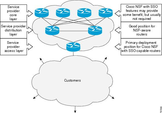
Figure 1 illustrates how SSO is typically deployed in service provider networks. In this example, Cisco NSF with SSO is primarily at the access layer (edge) of the service provider network. A fault at this point could result in loss of service for enterprise customers requiring access to the service provider network.
Figure 1 Cisco NSF with SSO Network Deployment: Service Provider Networks
For Cisco NSF protocols that require neighboring devices to participate in Cisco NSF, Cisco NSF-aware software images must be installed on those neighboring distribution layer devices. Additional network availability benefits might be achieved by applying Cisco NSF and SSO features at the core layer of your network; however, consult your network design engineers to evaluate your specific site requirements.
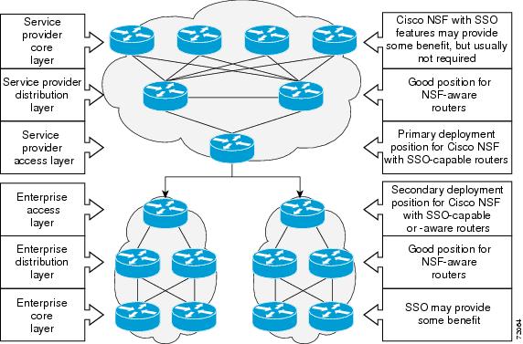
Additional levels of availability may be gained by deploying Cisco NSF with SSO at other points in the network where a single point of failure exists. Figure 2 illustrates an optional deployment strategy that applies Cisco NSF with SSO at the enterprise network access layer. In this example, each access point in the enterprise network represents another single point of failure in the network design. In the event of a switchover or a planned software upgrade, enterprise customer sessions would continue uninterrupted through the network.
Figure 2 Cisco NSF with SSO Network Deployment: Enterprise Networks
SSO Redundancy Modes
•
High System Availability
HSA mode allows you to install two RPs in a single router to improve system availability. This mode is available only on Cisco 7500 series routers. Supporting two RPs in a router provides the most basic level of increased system availability through a "cold restart" feature. A cold restart means that when one RP fails, the other RP reboots the router. Thus, the router is never in a failed state for very long, thereby increasing system availability.
Route Processor Redundancy
Router Processor Redundancy (RPR) allows Cisco software to be booted on the standby processor prior to switchover (a "cold boot"). In RPR, the standby RP loads a Cisco software image at boot time and initializes itself in standby mode; however, although the startup configuration is synchronized to the standby RP, system changes are not. In the event of a fatal error on the active RP, the system switches to the standby processor, which reinitializes itself as the active processor, reads and parses the startup configuration, reloads all of the line cards, and restarts the system.
Route Processor Redundancy Plus
In RPR+ mode, the standby RP is fully initialized. For RPR+ both the active RP and the standby RP must be running the same software image. The active RP dynamically synchronizes startup and the running configuration changes to the standby RP, meaning that the standby RP need not be reloaded and reinitialized (a "hot boot").
Additionally, on the Cisco 10000 and 12000 series Internet routers, the line cards are not reset in RPR+ mode. This functionality provides a much faster switchover between the processors. Information synchronized to the standby RP includes running configuration information, startup information (Cisco 7304, Cisco 7500, Cisco 10000, and Cisco 12000 series networking devices), and changes to the chassis state such as online insertion and removal (OIR) of hardware. Line card, protocol, and application state information is not synchronized to the standby RP.
Stateful Switchover Mode
SSO mode provides all the functionality of RPR+ in that Cisco software is fully initialized on the standby RP. In addition, SSO supports synchronization of line card, protocol, and application state information between RPs for supported features and protocols (a hot standby ).
Redundancy Modes by Platform and Software Release
Note
Table 1 through Table 5 show redundancy modes by platform and release.
Table 3 Redundancy Modes by Platform in Cisco IOS Release 12.2SR
7600
HSA
No
No
No
RPR
Yes
Yes
Yes
RPR+
Yes
Yes
Yes
SSO
Yes
Yes
Yes
Table 4 Redundancy Modes by Platform in Cisco IOS Release 12.2SX
CAT6500
HSA
No
RPR
Yes
RPR+
Yes
SSO
Yes
Route Processor Synchronization
In networking devices running SSO, both RPs must be running the same configuration so that the standby RP is always ready to assume control if the active RP fails.
To achieve the benefits of SSO, synchronize the configuration information from the active RP to the standby RP at startup and whenever changes to the active RP configuration occur. This synchronization occurs in two separate phases:
•
•
Bulk Synchronization During Initialization
When a system with SSO is initialized, the active RP performs a chassis discovery (discovery of the number and type of line cards and fabric cards, if available, in the system) and parses the startup configuration file.
The active RP then synchronizes this data to the standby RP and instructs the standby RP to complete its initialization. This method ensures that both RPs contain the same configuration information.
Even though the standby RP is fully initialized, it interacts only with the active RP to receive incremental changes to the configuration files as they occur. Executing CLI commands on the standby RP is not supported.
During system startup, the startup configuration file is copied from the active RP to the standby RP. Any existing startup configuration file on the standby RP is overwritten. The startup configuration is a text file stored in the NVRAM of the RP. It is synchronized whenever you perform the following operations:
•
•
•
•
•
•
•
Incremental Synchronization
After both RPs are fully initialized, any further changes to the running configuration or active RP states are synchronized to the standby RP as they occur. Active RP states are updated as a result of processing protocol information, external events (such as the interface becoming up or down), or user configuration commands (using Cisco IOS commands or Simple Network Management Protocol [SNMP]) or other internal events.
Changes to the running configuration are synchronized from the active RP to the standby RP. In effect, the command is run on both the active and the standby RP.
Configuration changes caused by an SNMP set operation are synchronized on a case-by-case basis. Only two SNMP configuration set operations are supported:
•
•
Routing and forwarding information is synchronized to the standby RP:
•
•
Chassis state changes are synchronized to the standby RP. Changes to the chassis state due to line card insertion or removal are synchronized to the standby RP.
Changes to the line card states are synchronized to the standby RP. Line card state information is initially obtained during bulk synchronization of the standby RP. Following bulk synchronization, line card events, such as whether the interface is up or down, received at the active processor are synchronized to the standby RP.
The various counters and statistics maintained in the active RP are not synchronized because they may change often and because the degree of synchronization they require is substantial. The volume of information associated with statistics makes synchronizing them impractical.
Not synchronizing counters and statistics between RPs may create problems for external network management systems that monitor this information.
Switchover Operation
•
Switchover Conditions
An automatic or manual switchover may occur under the following conditions:
•
•
•
The user can force the switchover from the active RP to the standby RP by using a CLI command. This manual procedure allows for a "graceful" or controlled shutdown of the active RP and switchover to the standby RP. This graceful shutdown allows critical cleanup to occur.
Note
Caution
Switchover Time
The time required by the device to switch over from the active RP to the standby RP varies by platform:
•
•
•
•
Although the newly active processor takes over almost immediately following a switchover, the time required for the device to begin operating again in full redundancy (SSO) mode can be several minutes, depending on the platform. The length of time can be due to a number of factors including the time needed for the previously active processor to obtain crash information, load code and microcode, and synchronize configurations between processors and line protocols and Cisco NSF-supported protocols.
The impact of the switchover time on packet forwarding depends on the networking device:
•
•
•
Online Removal of the Active RP
For Cisco 7500 series routers, online removal of the active RSP will automatically switch the redundancy mode to RPR. Online removal of the active RSP causes all line cards to reset and reload, which is equivalent to an RPR switchover, and results in a longer switchover time. When it is necessary to remove the active RP from the system, first issue a switchover command to switch from the active RSP to the standby RSP. When a switchover is forced to the standby RSP before the previously active RSP is removed, the network operation benefits from the continuous forwarding capability of SSO.
For Cisco 7304, Cisco 10000, and Cisco 12000 series Internet routers that are configured to use SSO, online removal of the active RP automatically forces a stateful switchover to the standby RP.
Single Line Card Reload
In Cisco 7500 series routers, a line card might fail to reach the quiescent state as a result of a hardware or software fault. In such cases, the failing line card must be reset. We recommend using the Single Line Card Reload (SLCR) feature to provide maximum assurance that SSO will continue forwarding packets on unaffected interfaces during switchover.
Note
The SLCR feature allows users to correct a line card fault on a Cisco 7500 series router by automatically reloading the microcode on a failed line card. During the SLCR process, all physical lines and routing protocols on the other line cards of the network backplane remain active.
The SLCR feature is not enabled by default. When you enable SSO, RPR+, or RPR, it is important that you enable SLCR also. For information on how to load and configure SLCR, refer to the Cisco 7500 Single Line Card Reload feature module.
Fast Software Upgrade
You can use Fast Software Upgrade (FSU) to reduce planned downtime. With FSU, you can configure the system to switch over to a standby RP that is preloaded with an upgraded Cisco software image. FSU reduces outage time during a software upgrade by transferring functions to the standby RP that has the upgraded Cisco software preinstalled. You can also use FSU to downgrade a system to an older version of Cisco software or have a backup system loaded for downgrading to a previous image immediately after an upgrade.
SSO must be configured on the networking device before performing FSU.
Note
Core Dump Operation
In networking devices that support SSO, the newly active primary processor runs the core dump operation after the switchover has taken place. Not having to wait for dump operations effectively decreases the switchover time between processors.
Following the switchover, the newly active RP will wait for a period of time for the core dump to complete before attempting to reload the formerly active RP. The time period is configurable. For example, on some platforms an hour or more may be required for the formerly active RP to perform a coredump, and it might not be site policy to wait that much time before resetting and reloading the formerly active RP. In the event that the core dump does not complete within the time period provided, the standby is reset and reloaded regardless of whether it is still performing a core dump.
The core dump process adds the slot number to the core dump file to identify which processor generated the file content.
Note
Virtual Template Manager for SSO
The virtual template manager feature for SSO provides virtual access interfaces for sessions that are not HA-capable and are not synchronized to the standby router. The virtual template manager uses a redundancy facility (RF) client to allow the synchronization of the virtual interfaces in real time as they are created.
The virtual databases have instances of distributed FIB entries on line cards. Line cards require synchronization of content and timing in all interfaces to the standby processor to avoid incorrect forwarding. If the virtual access interface is not created on the standby processor, the interface indexes will be corrupted on the standby router and line cards, which will cause problems with forwarding.
SSO-Aware Protocols and Applications
SSO-supported line protocols and applications must be SSO-aware. A feature or protocol is SSO-aware if it maintains, either partially or completely, undisturbed operation through an RP switchover. State information for SSO-aware protocols and applications is synchronized from active to standby to achieve stateful switchover for those protocols and applications.
The dynamically created state of SSO-unaware protocols and applications is lost on switchover and must be reinitialized and restarted on switchover.
SSO-aware applications are either platform-independent, such as in the case of line protocols or platform-dependent (such as line card drivers). Enhancements to the routing protocols (Cisco Express Forwarding, Open Shortest Path First, and Border Gateway Protocol [BGP]) have been made in the SSO feature to prevent loss of peer adjacency through a switchover; these enhancements are platform-independent.
The following protocols and applications are SSO-aware:
•
•
Line Protocols
SSO-aware line protocols synchronize session state information between the active and standby RPs to keep session information current for a particular interface. In the event of a switchover, session information need not be renegotiated with the peer. During a switchover, SSO-aware protocols also check the line card state to learn if it matches the session state information. SSO-aware protocols use the line card interface to exchange messages with network peers in an effort to maintain network connectivity.
•
•
•
Supported Line protocols by Platform
Table 6 through Table 10 indicates which line protocols are supported on various platforms and releases.
Table 9 Line Protocol Support in Cisco IOS Release 12.2SX
ATM
Cisco CAT6500
Yes
Cisco 7600
Yes
Frame Relay and Multilink Frame Relay
Cisco CAT6500
Yes1
Cisco 7600
Yes
PPP and Multilink PPP
Cisco CAT6500
Yes
Cisco 7600
Yes
HDLC
Cisco CAT6500
Yes
Cisco 7600
Yes
1 Frame Relay is supported, but Multilink Frame Relay is not.
ATM Stateful Switchover
With stateful switchover, ATM dynamic state information is synchronized between the active RP and standby RP. Thus when the active RP fails, the standby RP can take over without spending excessive time relearning the dynamic state information, and forwarding devices can continue to forward packets with only a few seconds of interruption (less on some platforms).
Note
Permanent Virtual Circuits
For ATM to support forwarding during and after switchover, ATM permanent virtual circuits (PVCs) must remain up not only within the networking device, but also within the ATM network.
In an ATM network, all traffic to or from an ATM interface is prefaced with a virtual path identifier (VPI) and virtual channel identifier (VCI). A VPI-VCI pair is considered a single virtual circuit. Each virtual circuit is a private connection to another node on the ATM network. In ATM SSO, the VPI-VCI pair is associated with a virtual circuit descriptor (VCD). ATM SSO uses VCD information in synchronizing VPI-VCI information to the standby RP.
Each virtual circuit is treated as a point-to-point or point-to-multipoint mechanism to another networking device or host and can support bidirectional traffic. On point-to-point subinterfaces, or when static mappings are configured, Inverse Address Resolution Protocol (ARP) need not run. In cases where dynamic address mapping is used, an Inverse ARP protocol exchange determines the protocol address to VPI-VCI mapping for the PVC. This process occurs as soon as the PVC on a multipoint subinterface makes the transition to active. If that process fails for some reason, the remote networking device may drop the Inverse ARP request if it has not yet seen the PVC transition to active. Inverse ARP runs every 60 seconds to relearn the dynamic address mapping information for the active RP.
ATM OAM Managed PVC or SVC Timeout
Operation, Administration, and Maintenance (OAM) F5 loopback cells must be echoed back on receipt by the remote host, thus demonstrating connectivity on the PVC between the router and the remote host. With ATM SSO, OAM loopback cells received on an interface must be echoed within 15 seconds before a PVC or switched virtual circuit (SVC) is declared down. By default, the OAM timeout is set to 10 seconds, followed by at most five retries sent at 1-second intervals. In the worst case, a switchover will begin just before expiration of the 10-second period, meaning that the PVC will go down within 5 seconds on the remote networking device if switchover has not completed within 5 seconds.
Note
Frame Relay and Multilink Frame Relay Stateful Switchover
With stateful switchover, Frame Relay and Multilink Frame Relay dynamic state information is synchronized between the active RP and standby RP. Thus when the active RP fails, the standby RP can take over without spending excessive time relearning the dynamic state information, and forwarding devices can continue to forward packets with only a few seconds of interruption (less on some platforms).
Permanent Virtual Circuits
For Frame Relay and Multilink Frame Relay to support forwarding during and after switchover, Frame Relay PVCs must remain up not only within the networking device, but also within the Frame Relay network.
In many cases the networking devices are connected to a switch, rather than back-to-back to another networking device, and that switch is not running Cisco software. The virtual circuit state is dependent on line state. PVCs are down when the line protocol is down. PVCs are up when the line protocol is up and the PVC status reported by the adjacent switch is active.
On point-to-point subinterfaces, or when static mappings are configured, Inverse ARP need not run. In cases where dynamic address mapping is used, an Inverse ARP protocol exchange determines the protocol address to data-link connection identifier (DLCI) mapping for the PVC. This exchange occurs as soon as the multipoint PVC makes the transition to active. If the exchange fails for some reason, for example, the remote networking device may drop the Inverse ARP request if it has not yet seen the PVC transition to active—any outstanding requests are run off a timer, with a default of 60 seconds.
Keepalive Messages
A crucial factor in maintaining PVCs is the delivery of Local Management Interface (LMI) protocol messages (keepalives) during switchover. This keepalive mechanism provides an exchange of information between the network server and the switch to verify that data is flowing.
If a number of consecutive LMI keepalives messages are lost or in error, the adjacent Frame Relay device declares the line protocol down and all PVCs on that interface are declared down within the Frame Relay network and reported as such to the remote networking device. The speed with which a switchover occurs is crucial to avoid the loss of keepalive messages.
The line protocol state depends on the Frame Relay keepalive configuration. With keepalives disabled, the line protocol is always up as long as the hardware interface is up. With keepalives enabled, LMI protocol messages are exchanged between the networking device and the adjacent Frame Relay switch. The line protocol is declared up after a number of consecutive successful LMI message exchanges.
The line protocol must be up according to both the networking device and the switch. The default number of exchanges to bring up the line protocol is implementation-dependent: Three is suggested by the standards; four is used on a Cisco Frame Relay switch, taking 40 seconds at the default interval of 10 seconds; and two is used on a Cisco networking device acting as a switch or when connected back-to-back. This default number could be extended if the LMI "autosense" feature is being used while the LMI type expected on the switch is determined. The number of exchanges is configurable, although the switch and router may not have the same owner.
The default number of lost messages or errors needed to bring down the line is three (two on a Cisco router). By default, if a loss of two messages is detected in 15 to 30 seconds, then a sequence number or LMI type error in the first message from the newly active RP takes the line down.
If a line goes down, consecutive successful LMI protocol exchanges (default of four over 40 seconds on a Cisco Frame Relay switch; default of two over 20 seconds on a Cisco device) will bring the line back up again.
PPP and Multilink PPP Stateful Switchover
With stateful switchover, specific PPP state information is synchronized between the active RP and standby RP. Thus when the active RP fails, the standby RP can take over without spending excessive time renegotiating the setup of a given link. As long as the physical link remains up, forwarding devices can continue to forward packets with only a few seconds of interruption (less on some platforms). Single-link PPP and Multilink PPP (MLP) sessions are maintained during RP switchover for IP connections only.
PPP and MLP support many Layer 3 protocols such as IPX and IP. Only IP links are supported in SSO. Links supporting non IP traffic will momentarily renegotiate and resume forwarding following a switchover. IP links will forward IP traffic without renegotiation.
A key factor in maintaining PPP session integrity during a switchover is the use of keepalive messages. This keepalive mechanism provides an exchange of information between peer interfaces to verify data and link integrity. Depending on the platform and configuration, the time required for switchover to the standby RP might exceed the keepalive timeout period. PPP keepalive messages are started when the physical link is first brought up. By default, keepalive messages are sent at 10-second intervals from one PPP interface to the other PPP peer.
If five consecutive keepalive replies are not received, the PPP link would be taken down on the newly active RP. Caution should be used when changing the keepalive interval duration to any value less than the default setting.
Only in extremely rare circumstances could the RP switchover time exceed the default 50-second keepalive duration. In the unlikely event this time is exceeded, the PPP links would renegotiate with the peers and resume IP traffic forwarding.
Note
HDLC Stateful Switchover
With stateful switchover, High-Level Data Link Control (HDLC) synchronizes the line protocol state information. Additionally, the periodic timer is restarted for interfaces that use keepalive messages to verify link integrity. Link state information is synchronized between the active RP and standby RP. The line protocols that were up before the switchover remain up afterward as long as the physical interface remains up. Line protocols that were down remain down.
A key factor in maintaining HDLC link integrity during a switchover is the use of keepalive messages. This keepalive mechanism provides an exchange of information between peer interfaces to verify data is flowing. HDLC keepalive messages are started when the physical link is first brought up. By default, keepalive messages are sent at 10-second intervals from one HDLC interface to the other.
HDLC waits at least three keepalive intervals without receiving keepalive messages, sequence number errors, or a combination of both before it declares a line protocol down. If the line protocol is down, SSO cannot support continuous forwarding of user session information in the event of a switchover.
Note
Quality of Service
The modular QoS CLI (MQS)-based QoS feature maintains a database of various objects created by the user, such as those used to specify traffic classes, actions for those classes in traffic policies, and attachments of those policies to different traffic points such as interfaces. With SSO, QoS synchronizes that database between the primary and secondary RP.
IPv6 Support for Stateful Switchover
IPv6 neighbor discovery supports SSO using Cisco Express Forwarding. When switchover occurs, the Cisco Express Forwarding adjacency state, which is checkpointed, is used to reconstruct the neighbor discovery cache.
Line Card Drivers
Platform-specific line card device drivers are bundled with the Cisco software image for SSO and are correct for a specific image, meaning they are designed to be SSO-aware.
Line cards used with the SSO feature periodically generate status events that are forwarded to the active RP. Information includes the line up or down status, and the alarm status. This information helps SSO support bulk synchronization after standby RP initialization and support state reconciliation and verification after a switchover.
Line cards used with the SSO feature also have the following requirements:
•
•
•
Note
APS
RPR+ and SSO support allow the automatic protection switching (APS) state to be preserved in the event of failover.
Routing Protocols and Nonstop Forwarding
Cisco nonstop forwarding (NSF) works with SSO to minimize the amount of time a network is unavailable to its users following a switchover. When a networking device restarts, all routing peers of that device usually detect that the device went down and then came back up. This down-to-up transition results in what is called a "routing flap," which could spread across multiple routing domains. Routing flaps caused by routing restarts create routing instabilities, which are detrimental to the overall network performance. Cisco NSF helps to suppress routing flaps, thus improving network stability.
Cisco NSF allows for the forwarding of data packets to continue along known routes while the routing protocol information is being restored following a switchover. With Cisco NSF, peer networking devices do not experience routing flaps. Data traffic is forwarded through intelligent line cards while the standby RP assumes control from the failed active RP during a switchover. The ability of line cards to remain up through a switchover and to be kept current with the FIB on the active RP is key to Cisco NSF operation.
A key element of Cisco NSF is packet forwarding. In Cisco networking devices, packet forwarding is provided by Cisco Express Forwarding. Cisco Express Forwarding maintains the FIB, and uses the FIB information that was current at the time of the switchover to continue forwarding packets during a switchover. This feature eliminates downtime during the switchover.
Cisco NSF supports the BGP, IS-IS, and OSPF routing protocols. In general, these routing protocols must be SSO-aware to detect a switchover and recover state information (converge) from peer devices. Each protocol depends on Cisco Express Forwarding to continue forwarding packets during switchover while the routing protocols rebuild the Routing Information Base (RIB) tables.
Note
Network Management
Network management support for SSO is provided through the synchronization of specific SNMP data between the active and standby RPs. From a network management perspective, this functionality helps to provide an uninterrupted management interface to the network administrator.
Note
SSO for Circuit Emulation Services
SSO for circuit emulation services (CES) for TDM pseudowires provides the ability to switch an incoming DS1/T1/E1 on one SPA to another SPA on same SIP or onto a different SIP.
How to Configure Stateful Switchover
•
•
•
•
•
Copying an Image onto an RP
Note
SUMMARY STEPS
1.
2.
3.
4.
DETAILED STEPS
Setting the Configuration Register and Boot Variable
Note
SUMMARY STEPS
1.
2.
3.
4.
5.
6.
7.
8.
9.
DETAILED STEPS
Configuring SSO
Configuring SSO
Note
Prerequisites
Image to be used by active or standby RP at initialization must be available on the local flash device.
SUMMARY STEPS
1.
2.
3.
4.
5.
6.
7.
DETAILED STEPS
Configuring Frame Relay and Multilink Frame Relay Autosynchronization LMI Sequence Numbers
SUMMARY STEPS
1.
2.
3.
DETAILED STEPS
Verifying SSO Configuration
SUMMARY STEPS
1.
2.
3.
DETAILED STEPS
Performing a Fast Software Upgrade
Note
SUMMARY STEPS
1.
2.
3.
4.
5.
no hw-module slot slot-number image file-spec6.
hw-module slot slot-number image file-spec7.
8.
9.
10.
11.
12.
13.
reload standby-cpu14.
DETAILED STEPS
Troubleshooting Stateful Switchover
Resolving Possible SSO Problem Situations
Step 1
Router# show redundancy historyStep 2
Step 3
Step 4
This is normal behavior. Until the FSU procedure is complete, each RP will be running a different software version. While the RPs are running different software versions, the mode will change to either RPR or RPR+, depending on the device. The device will change to SSO mode once the upgrade has completed.
Step 5
Step 6
•
•
•
Troubleshooting SSO
SUMMARY STEPS
1.
2.
3.
4.
5.
6.
7.
8.
9.
10.
states | inter-device]11.
DETAILED STEPS
Configuration Examples for Configuring Stateful Switchover
•
•
•
Example: Verifying that SSO Is Configured on Various Platforms
In the following several examples, the show redundancy command is used to verify that SSO is configured on the device. Sample output is provided for several platforms.
Cisco 7304 Router
Router# show redundancyRedundant System Information :Available system uptime = 2 minutesSwitchovers system experienced = 0Standby failures = 0Last switchover reason = noneHardware Mode = DuplexConfigured Redundancy Mode = SSOOperating Redundancy Mode = SSOMaintenance Mode = DisabledCommunications = UpCurrent Processor Information :Active Location = slot 0Current Software state = ACTIVEUptime in current state = 2 minutesImage Version = Cisco Internetwork Operating System SoftwareIOS (tm) 7300 Software (C7300-P-M), Version 12.2(20)S6, RELEASE SOFTWARE (fc4)Technical Support: http://www.cisco.com/techsupportCopyright (c) 1986-2004 by cisco Systems, Inc.In the following several examples, the show redundancy command is used to verify that SSO is configured on the device. Sample output is provided for several platforms.
Cisco 7304 Router
Router# show redundancyRedundant System Information :Available system uptime = 2 minutesSwitchovers system experienced = 0Standby failures = 0Last switchover reason = noneHardware Mode = DuplexConfigured Redundancy Mode = SSOOperating Redundancy Mode = SSOMaintenance Mode = DisabledCommunications = UpCurrent Processor Information :Active Location = slot 0Current Software state = ACTIVEUptime in current state = 2 minutesImage Version = Cisco Internetwork Operating System SoftwareIOS (tm) 7300 Software (C7300-P-M), Version 12.2(20)S6, RELEASE SOFTWARE (fc4)Technical Support: http://www.cisco.com/techsupportCopyright (c) 1986-2004 by cisco Systems, Inc.Compiled Fri 29-Oct-04 14:39BOOT =CONFIG_FILE =BOOTLDR = bootdisk:c7300-boot-mz.121-13.EX1Configuration register = 0x0Peer Processor Information :Standby Location = slot 2Current Software state = STANDBY HOTUptime in current state = 1 minuteImage Version = Cisco Internetwork Operating System SoftwareIOS (tm) 7300 Software (C7300-P-M), Version 12.2(20)S6, RELEASE SOFTWARE (fc4)Technical Support: http://www.cisco.com/techsupportCopyright (c) 1986-2004 by cisco Systems, Inc.Compiled Fri 29-Oct-04 14:39BOOT =CONFIG_FILE =BOOTLDR = bootdisk:c7300-boot-mz.121-13.EX1Configuration register = 0x0Cisco 7500 Series Router
Router# show redundancyOperating mode is ssoredundancy mode ssohw-module slot 6 image disk0:rsp-pv-mzhw-module slot 7 image disk0:rsp-pv-mzActive in slot 6Standby in slot 7The system total uptime since last reboot is 2 weeks, 23 hours 41 minutes.The system has experienced 4 switchovers.The system has been active (become master) for 21 hours 1 minute.Reason for last switchover: User forced.Cisco 10000 Series Internet Router
Router# show redundancyPRE A (This PRE) : ActivePRE B : StandbyOperating mode : SSOUptime since this PRE switched to active : 13 hours, 51 minutesTotal system uptime from reload : 15 hours, 8 minutesSwitchovers this system has experienced : 2Standby failures since this PRE active : 0The standby PRE has been up for : 13 hours, 47 minutesStandby PRE information....Standby is up.Standby has 524288K bytes of memory.Standby BOOT variable = disk0:c10k-p10-mzStandby CONFIG_FILE variable =Standby BOOTLDR variable =Standby Configuration register is 0x2102Standby version:Cisco Internetwork Operating System SoftwareIOS (tm) 10000 Software (C10K-P10-M), Version 12.0(20020221:082811)[REL-bowmore.ios-weekly 100]Copyright (c) 1986-2002 by cisco Systems, Inc.Compiled Thu 21-Feb-02 03:28Active version:Cisco Internetwork Operating System SoftwareIOS (am) 10000 Software (C10K-P10-M), Version 12.0(20020221:082811)[REL-bowmore.ios-weekly 100]Copyright (c) 1986-2002 by cisco Systems, Inc.Compiled Thu 21-Feb-02 03:28Cisco 12000 Series Internet Router
Router# show redundancyActive GRP in slot 4:Standby GRP in slot 5:Preferred GRP: noneOperating Redundancy Mode: SSOAuto synch: startup-config running-configswitchover timer 3 seconds [default]Cisco ASR 1000 Series Router
Router# show redundancy statesmy state = 13 -ACTIVEpeer state = 4 -STANDBY COLDMode = DuplexUnit ID = 48Redundancy Mode (Operational) = rprRedundancy Mode (Configured) = rprRedundancy State = rprMaintenance Mode = DisabledManual Swact = enabledCommunications = Upclient count = 66client_notification_TMR = 30000 millisecondsRF debug mask = 0x0Example: Verifying that SSO Is Operating on the Device
In the following several examples, the show redundancy command with the states keyword is used to verify that SSO is configured on the device. Sample output is provided for several platforms.
Cisco 7304 Router
Router# show redundancy statesmy state = 13 -ACTIVEpeer state = 8 -STANDBY HOTMode = DuplexUnit ID = 0Redundancy Mode (Operational) = SSORedundancy Mode (Configured) = SSOSplit Mode = DisabledManual Swact = EnabledCommunications = Upclient count = 18client_notification_TMR = 30000 millisecondsRF debug mask = 0x0Cisco 7500 Series Router
Router# show redundancy statesmy state = 13 -ACTIVEpeer state = 8 -STANDBY HOTMode = DuplexUnit ID = 7Redundancy Mode = ssoMaintenance Mode = DisabledManual Swact = EnabledCommunications = Upclient count = 12client_notification_TMR = 30000 millisecondsRF debug mask = 0x0Cisco 10000 Series Internet Router
Router# show redundancy statesmy state = 13 -ACTIVEpeer state = 8 -STANDBY HOTMode = DuplexUnit = Preferred PrimaryUnit ID = 0Redundancy Mode = SSOMaintenance Mode = DisabledManual Swact = EnabledCommunications = Upclient count =14client_notification_TMR = 30000 millisecondsRF debug mask = 0x0Cisco 12000 Series Internet Router
Router# show redundancy statesmy state = 13 -ACTIVEpeer state = 8 -STANDBY HOTMode = DuplexUnit ID = 4Redundancy Mode = SSOMaintenance Mode = DisabledManual Swact = EnabledCommunications = Upclient count = 14client_notification_TMR = 30000 millisecondsRF debug mask = 0xCisco ASR 1000 Series Router
Router# show redundancy statesmy state = 13 -ACTIVEpeer state = 4 -STANDBY COLDMode = DuplexUnit ID = 48Redundancy Mode (Operational) = rprRedundancy Mode (Configured) = rprRedundancy State = rprMaintenance Mode = DisabledManual Swact = enabledCommunications = Upclient count = 66client_notification_TMR = 30000 millisecondsRF debug mask = 0x0Example: Verifying SSO Protocols and Applications
Enter the show redundancy command with the client keyword to display the list of applications and protocols that have registered as SSO protocols or applications. You can also verify the list of supported line protocols.
Cisco 7304 Router
Router# show redundancy clientsclientID = 0 clientSeq = 0 RF_INTERNAL_MSGclientID = 29 clientSeq = 60 Redundancy Mode RFclientID = 25 clientSeq = 130 CHKPT RFclientID = 1314 clientSeq = 137 7300 Platform RFclientID = 22 clientSeq = 140 Network RF ClientclientID = 24 clientSeq = 150 CEF RRP RF ClientclientID = 5 clientSeq = 170 RFS clientclientID = 23 clientSeq = 220 Frame RelayclientID = 49 clientSeq = 225 HDLCclientID = 20 clientSeq = 310 IPROUTING NSF RF cliclientID = 21 clientSeq = 320 PPP RFclientID = 34 clientSeq = 350 SNMP RF ClientclientID = 52 clientSeq = 355 ATMclientID = 35 clientSeq = 360 History RF ClientclientID = 54 clientSeq = 530 SNMP HA RF ClientclientID = 75 clientSeq = 534 VRF commonclientID = 57 clientSeq = 540 ARPclientID = 65000 clientSeq = 65000 RF_LAST_CLIENTCisco 7500 Series Router
Router# show redundancy clientsclientID = 0 clientSeq = 0 RF_INTERNAL_MSGclientID = 25 clientSeq = 130 CHKPT RFclientID = 22 clientSeq = 140 Network RF ClientclientID = 24 clientSeq = 150 CEF RRP RF ClientclientID = 37 clientSeq = 151 MDFS RRP RF ClientclientID = 23 clientSeq = 220 FRAME RELAYclientID = 49 clientSeq = 225 HDLCclientID = 20 clientSeq = 310 IPROUTING NSF RF cliclientID = 21 clientSeq = 320 PPP RFclientID = 34 clientSeq = 330 SNMP RF ClientclientID = 29 clientSeq = 340 ATMclientID = 35 clientSeq = 350 History RF ClientclientID = 50 clientSeq = 530 SNMP HA RF ClientclientID = 65000 clientSeq = 65000 RF_LAST_CLIENTCisco 10000 Series Internet Routere
Router# show redundancy clientsclientID = 0 clientSeq = 0 RF_INTERNAL_MSGclientID = 25 clientSeq = 130 CHKPT RFclientID = 22 clientSeq = 140 Network RF ClientclientID = 24 clientSeq = 150 CEF RRP RF ClientclientID = 26 clientSeq = 160 C10K RF ClientclientID = 5 clientSeq = 170 RFS clientclientID = 23 clientSeq = 220 Frame RelayclientID = 49 clientSeq = 225 HDLCclientID = 20 clientSeq = 310 IPROUTING NSF RF cliclientID = 21 clientSeq = 320 PPP RFclientID = 34 clientSeq = 330 SNMP RF ClientclientID = 29 clientSeq = 340 ATMclientID = 35 clientSeq = 350 History RF ClientclientID = 65000 clientSeq = 65000 RF_LAST_CLIENTCisco 12000 Series Internet Router
Router# show redundancy clientsclientID = 0 clientSeq = 0 RF_INTERNAL_MSGclientID = 25 clientSeq = 130 CHKPT RFclientID = 27 clientSeq = 132 C12K RF COMMON ClientclientID = 30 clientSeq = 135 Redundancy Mode RFclientID = 22 clientSeq = 140 Network RF ClientclientID = 24 clientSeq = 150 CEF RRP RF ClientclientID = 37 clientSeq = 151 MDFS RRP RF ClientclientID = 5 clientSeq = 170 RFS clientclientID = 23 clientSeq = 220 Frame RelayclientID = 49 clientSeq = 225 HDLCclientID = 20 clientSeq = 310 IPROUTING NSF RF cliclientID = 21 clientSeq = 320 PPP RFclientID = 34 clientSeq = 330 SNMP RF ClientclientID = 29 clientSeq = 340 ATMclientID = 35 clientSeq = 350 History RF ClientclientID = 50 clientSeq = 530 SNMP HA RF ClientclientID = 65000 clientSeq = 65000 RF_LAST_CLIENTCisco ASR 1000 Series Router
Router# show redundancy clientsclientID = 0 clientSeq = 0 RF_INTERNAL_MSGclientID = 29 clientSeq = 60 Redundancy Mode RFclientID = 139 clientSeq = 62 IfIndexclientID = 25 clientSeq = 69 CHKPT RFclientID = 1340 clientSeq = 90 ASR1000-RP PlatformclientID = 1501 clientSeq = 91 Cat6k CWAN HAclientID = 78 clientSeq = 95 TSPTUN HAclientID = 305 clientSeq = 96 Multicast ISSU ConsoclientID = 304 clientSeq = 97 IP multicast RF ClieclientID = 22 clientSeq = 98 Network RF ClientclientID = 88 clientSeq = 99 HSRPclientID = 114 clientSeq = 100 GLBPclientID = 1341 clientSeq = 102 ASR1000 DPIDXclientID = 1505 clientSeq = 103 Cat6k SPA TSMclientID = 1344 clientSeq = 110 ASR1000-RP SBC RFclientID = 227 clientSeq = 111 SBC RFclientID = 71 clientSeq = 112 XDR RRP RF ClientclientID = 24 clientSeq = 113 CEF RRP RF ClientclientID = 146 clientSeq = 114 BFD RF ClientclientID = 306 clientSeq = 120 MFIB RRP RF ClientclientID = 1504 clientSeq = 128 Cat6k CWAN InterfaceclientID = 75 clientSeq = 130 Tableid HAclientID = 401 clientSeq = 131 NAT HAclientID = 402 clientSeq = 132 TPM RF clientclientID = 5 clientSeq = 135 Config Sync RF clienclientID = 68 clientSeq = 149 Virtual Template RFclientID = 23 clientSeq = 152 Frame RelayclientID = 49 clientSeq = 153 HDLCclientID = 72 clientSeq = 154 LSD HA ProcclientID = 113 clientSeq = 155 MFI STATIC HA ProcclientID = 20 clientSeq = 171 IPROUTING NSF RF cliclientID = 100 clientSeq = 173 DHCPCclientID = 101 clientSeq = 174 DHCPDclientID = 74 clientSeq = 183 MPLS VPN HA ClientclientID = 34 clientSeq = 185 SNMP RF ClientclientID = 52 clientSeq = 186 ATMclientID = 69 clientSeq = 189 AAAclientID = 118 clientSeq = 190 L2TPclientID = 82 clientSeq = 191 CCM RFclientID = 35 clientSeq = 192 History RF ClientclientID = 90 clientSeq = 204 RSVP HA ServicesclientID = 70 clientSeq = 215 FH COMMON RF CLIENTclientID = 54 clientSeq = 220 SNMP HA RF ClientclientID = 73 clientSeq = 221 LDP HAclientID = 76 clientSeq = 222 IPRMclientID = 57 clientSeq = 223 ARPclientID = 50 clientSeq = 230 FH_RF_Event_DetectorclientID = 1342 clientSeq = 240 ASR1000 SpaFlowclientID = 1343 clientSeq = 241 ASR1000 IF FlowclientID = 83 clientSeq = 255 AC RF ClientclientID = 84 clientSeq = 257 AToM managerclientID = 85 clientSeq = 258 SSMclientID = 102 clientSeq = 273 MQC QoSclientID = 94 clientSeq = 280 Config Verify RF cliclientID = 135 clientSeq = 289 IKE RF ClientclientID = 136 clientSeq = 290 IPSEC RF ClientclientID = 130 clientSeq = 291 CRYPTO RSAclientID = 148 clientSeq = 296 DHCPv6 RelayclientID = 4000 clientSeq = 303 RF_TS_CLIENTclientID = 4005 clientSeq = 305 ISSU Test ClientclientID = 93 clientSeq = 309 Network RF 2 ClientclientID = 205 clientSeq = 311 FEC ClientclientID = 141 clientSeq = 319 DATA DESCRIPTOR RF CclientID = 4006 clientSeq = 322 Network ClockclientID = 225 clientSeq = 326 VRRPclientID = 65000 clientSeq = 336 RF_LAST_CLIENTAdditional References
Related Documents
Cisco IOS commands
Cisco High Availability commands
DHCP proxy client
"ISSU and SSO--DHCP High Availability Features" module in the Cisco IOS IP Addressing Services Configuration Guide
MPLS high availability
"MPLS High Availability: Overview" module in the Cisco Multiprotocol Label Switching Configuration Guide
NSF/SSO - 802.3ah OAM Support
NSF/SSO - Any Transport over MPLS (AToM)
NSF/SSO - E-LMI Support
Configuring Ethernet Local Management Interface at a Provider Edge
SSO - BFD (Admin Down)
SSO GLBP
"GLBP SSO" module in the Cisco IOS IP Application Services Configuration Guide
SSO HSRP
"Configuring HSRP" module in the Cisco IOS IP Application Services Configuration Guide
•
•
•
Monitoring and Maintaining Multicast HA Operations (NSF/SSO and ISSU)
SSO and RPR on the Cisco ASR 1000 series routers
Cisco ASR 1000 Series Aggregation Services Routers Software Configuration Guide
SSO VRRP
"Configuring VRRP" module in the Cisco IOS IP Application Services Configuration Guide
Basic IPv6 configuration
"Implementing IPv6 Addressing and Basic Connectivity" module in the Cisco IOS IPv6 Configuration Guide
Virtual Private LAN Services
Standards
No new or modified standards are supported by this feature, and support for existing standards has not been modified by this feature.
—
MIBs
RFCs
Technical Assistance
Feature Information for Stateful Switchover
Table 11 lists the features in this module and provides links to specific configuration information.
Use Cisco Feature Navigator to find information about platform support and software image support. Cisco Feature Navigator enables you to determine which software images support a specific software release, feature set, or platform. To access Cisco Feature Navigator, go too http://www.cisco.com/go/cfn. An account on Cisco.com is not required.
Note
Cisco and the Cisco Logo are trademarks of Cisco Systems, Inc. and/or its affiliates in the U.S. and other countries. A listing of Cisco's trademarks can be found at www.cisco.com/go/trademarks. Third party trademarks mentioned are the property of their respective owners. The use of the word partner does not imply a partnership relationship between Cisco and any other company. (1005R)
Any Internet Protocol (IP) addresses and phone numbers used in this document are not intended to be actual addresses and phone numbers. Any examples, command display output, and figures included in the document are shown for illustrative purposes only. Any use of actual IP addresses or phone numbers in illustrative content is unintentional and coincidental.
© 2002-2010 Cisco Systems, Inc. All rights reserved.