-
Cisco Transport Manager User's Guide, 7.2
-
Preface
-
Chapter 1: Introduction
-
Chapter 2: Basic Concepts
-
Chapter 3: Building the Network
-
Chapter 4: Maintaining an Efficient Network
-
Chapter 5: Configuring Hardware
-
Chapter 6: Provisioning Cards
-
Chapter 7: Provisioning Services and Connections
-
Chapter 8: Managing Security
-
Chapter 9: Managing Faults
-
Chapter 10: Managing Performance
-
Chapter 11: Managing Inventory
-
Chapter 12: Managing Southbound and Northbound Interfaces
-
Appendix A: Icons and Menus Displayed in CTM
-
Appendix B: NE Explorer Information
-
Appendix C: Slot Property Information--Common, DWDM, Electrical, and Ethernet Cards
-
Appendix D: Slot Property Information--FC_MR-4, FMEC, Multirate, Optical, and Transponder Cards
-
Appendix E: Statistics Summary for Voice-Enabled Products
-
Appendix F: Traps Config Group
-
Appendix G: Performance Data
-
Appendix H: Real-Time Counters for Voice-Enabled Products
-
Appendix I: Error Messages
-
Appendix J: Using CiscoView to Configure and Monitor ONS 15501, ONS 15530, and ONS 15540 NEs
-
Appendix K: Troubleshooting
-
Appendix L: Open Source License Acknowledgement
-
Glossary
-
 Feedback
Table Of Contents
Provisioning Services and Connections
7.2.1 Circuit Table Launch Points
7.2.2 Circuit Table Management Tasks
7.2.3 Viewing the Circuit Table
7.2.4 Creating Circuits Using the Circuit Wizard
7.2.5 Modifying a Circuit on CTC-Based NEs
7.2.6 Modifying a Circuit on CRS-1 NEs
7.2.7 Modifying a Circuit on ONS 15530 or ONS 15540 NEs
7.2.8 Summary of Edit Circuit Options
7.2.9 Updating Circuits on CRS-1 or CTC-Based NEs
7.2.10 Merging Circuits on CTC-Based NEs
7.2.12 Deleting a Circuit on CRS-1 or CTC-Based NEs
7.2.14 Viewing VLAN Information
7.2.15 Viewing the ONS 15530 and ONS 15540 Circuit Table
7.2.16 Viewing Circuits in the Circuit Path Table—ONS 15530 and ONS 15540
7.2.17 Viewing Circuits in the Circuit Path Span Table—ONS 15530 and ONS 15540
7.2.18 Viewing VCAT Member Circuits
7.2.19 Creating VCAT Member Circuits
7.2.20 Filtering the Circuit Table
7.2.21 Tracing a Circuit on CRS-1 or CTC-Based NEs
7.2.22 Modifying a Trace on CTC-Based NEs
7.2.23 Managing Circuit Notes on CTC-Based NEs
7.2.24 Managing Circuit Rolls on CTC-Based NEs
7.3.2 Creating a BLSR for an Individual Node
7.3.3 Creating BLSRs for Multiple Nodes Simultaneously
7.3.4 Viewing the BLSR Ring Map Table
7.3.5 Viewing the BLSR Squelch Table
7.3.8 Changing the BLSR Exercise Interval
7.3.9 Using the BLSR Upgrade Table
7.3.11 Filtering the BLSR Table
7.4.1 Viewing the MS-SPRing Table
7.4.2 Creating an MS-SPRing for an Individual Node
7.4.3 Creating MS-SPRings for Multiple Nodes Simultaneously
7.4.5 Using the MS-SPRing Upgrade Table
7.4.7 Viewing the MS-SPRing Ring Map Table
7.4.8 Viewing the MS-SPRing Squelch Table
7.4.10 Changing the MS-SPRing Exercise Interval
7.4.11 Filtering the MS-SPRing Table
7.5 Managing VLANs for E-Series Cards
7.6 Managing VLANs (ML-Series Cards)
7.7 Provisioning Data Services
7.7.1 Layer 2 Topology Table Management Tasks
7.7.2 Initializing Layer 2 Cards
7.7.3 Backing Up and Restoring ML Configuration Files on Layer 2 Cards
7.7.4 Naming Convention for Discovered Layer 2 Topologies
7.7.5 Provisioning the Layer 2 Topology
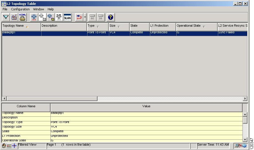
7.7.6 Viewing the L2 Topology Table
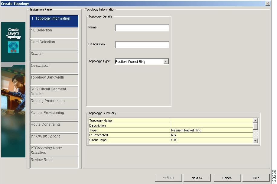
7.7.7 Creating a Layer 2 Topology
7.7.8 Deleting a Layer 2 Topology
7.7.9 Enabling a Layer 2 Service
7.7.10 Modifying a Layer 2 Topology
7.7.11 Filtering the Layer 2 Topology Table
7.7.12 Modifying Ports in a Layer 2 Topology
7.7.13 Inserting or Deleting a Card on an RPR Topology
7.7.14 Layer 2 Service Management Tasks
7.7.15 Changing the Framing Mode for ML-Series Cards
7.7.16 Provisioning ML-Series Cards to Receive SNMP Traps
7.8.1 QoS Profile Management Tasks
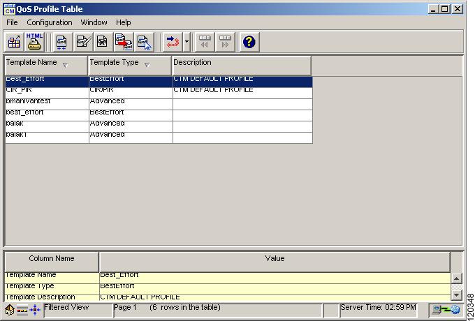
7.8.2 Viewing the QoS Profile Table
7.8.5 Duplicating a QoS Profile
7.8.7 Viewing the QoS Classes Table
7.9.1 Viewing the DWDM Ring Table
7.9.4 Filtering the DWDM Ring Table
7.10.1 Calculating a DWDM Connection
7.10.2 Creating a DWDM Connection
7.10.3 Deleting a DWDM Connection
7.10.4 Importing a Cisco MetroPlanner Configuration File
7.10.5 Provisioning a DWDM Node Manually
7.10.6 Provisioning the Power Level of DWDM Nodes
7.10.7 Checking the Span Loss Between DWDM Nodes
7.10.8 Enabling and Disabling APC
7.10.9 Monitoring the Channel Power for ROADM Nodes
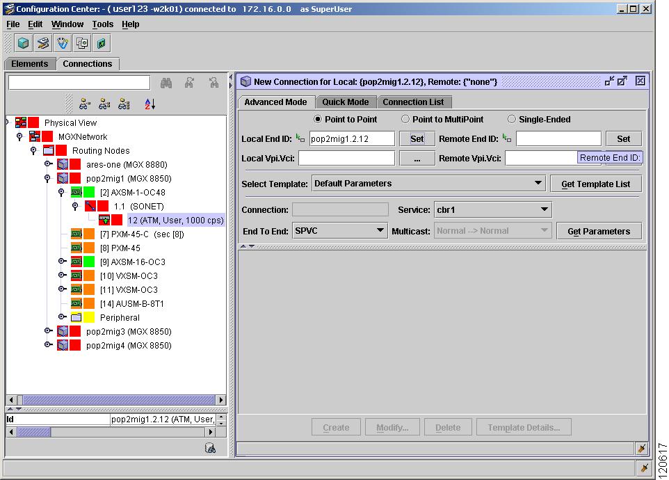
7.11 What Is Connection Provisioning?
7.11.1 What Type of Connection Is Available?
7.11.2 Where Do I Find Information About Connections?
7.11.3 How Do I Create, Modify, and Delete Voice Connections?
7.11.4 How Do I Configure Connection Templates?
7.11.5 How Can I Test the Connections?
Provisioning Services and Connections
This chapter describes how to use CTM to provision network services. It also details the tasks required to create new connections, and display, modify, and delete existing connections. This chapter includes the following sections:
•
Managing VLANs for E-Series Cards
•
•
7.1 Overview
A metro network is a network that aggregates customer traffic and connects customers to services. The metro network is responsible for receiving network traffic from long-haul transport networks and routing this traffic to and from enterprises and end users.
The service point-of-presence (POP) performs service adaptation and packet switching. This layer performs the following functions:
•
•
•
The service POP is the hub of high-value Internet services. The core network, where optical technologies predominate, is the domain of the long-haul carrier. This high-speed transport fabric interconnects service POPs and has traditionally been built as SONET ring architectures.
CTM simplifies operations support system (OSS) integration for service providers for the end-to-end management of transport networks.
7.2 Managing Circuits
A circuit represents an end-to-end connection between two or more connection termination points (CTPs). A circuit consists of an alternating series of cross-connections and link connections. In its simplest form, a circuit consists of a single cross-connection (if the circuit is defined between two CTPs on the same NE). A circuit can be bidirectional or unidirectional, point-to-point (PTP) or point-to-multipoint, and protected or unprotected.
CTM allows you to create unidirectional and bidirectional circuits for CTC-based NEs and DWDM optical channel client connection (OCHCC) circuits for CRS-1 NEs. For unidirectional path switched ring (UPSR) circuits, you can create revertive or nonrevertive circuits. CTM can route the circuits automatically, or you can route them manually. For CRS-1 and CTC-based NEs (including the ONS 15305 R3.0), circuits can be viewed, created, modified, traced, and deleted. For the ONS 15530 or ONS 15540, a circuit is an end-to-end connection between two ports on ONS 15530 or ONS 15540 NEs in terms of lambda (wavelength). For the ONS 155xx, circuit services provide the following major capabilities:
•
•
•
•
Note
For ONS 15305 NE releases 3.0 and later, circuits can be created in CTM, CTC, and CEC. Circuits that are created in CTM or CTC can be managed in CTM, CTC, and CEC. But circuits that are created in CEC show unpredictable and erroneous behavior in CTM and CTC.
For ONS 15305 NE releases earlier than R3.0, the circuit information is not available in CTM. Circuits can be created in CEC but cannot be managed in CTM.
Note
The following table defines the circuit terms and options that are used throughout this chapter.
7.2.1 Circuit Table Launch Points
The following table describes the various launch points and the expected behavior for the Circuit table.
7.2.2 Circuit Table Management Tasks
The following table describes the various tasks that can be carried out from the Circuit table and the recommended order in which to complete these tasks.
Table 7-3 Circuit Table Management Tasks
View the Circuit table
The Circuit table displays the circuit information for all circuits that make up the topology.
From the Domain Explorer, choose Configuration > CTC-Based SONET NEs, CTC-Based SDH NEs, or Cisco CRS-1 > Circuit Table
—
Create a circuit
The Circuit wizard allows you to create a circuit between NEs in the same group or subnetwork.
Configuration > Create Circuit
Modify a circuit
The Modify Circuit dialog box allows you to change circuit information for selected circuits.
Configuration > Modify Circuit
Modifying a Circuit on CTC-Based NEs
Modifying a Circuit on CRS-1 NEs
Update a circuit
You need to update circuits after adding nodes to the network.
From the Domain Explorer, choose Configuration > CTC-Based SONET NEs, CTC-Based SDH NEs, or Cisco CRS-1 > Update Circuit
—
Merge circuits on CTC-based NEs
Use the circuit merge feature to merge different circuits into one or more new circuits.
Configuration > Merge Table
Repair a circuit on CTC-based NEs
Use the Repair Circuit window to repair circuits.
From the Domain Explorer, choose Configuration > CTC-Based SONET NEs or CTC-Based SDH NEs > Repair Circuit
—
Delete a circuit
Allows you to delete an existing circuit. You can also select and delete multiple circuits.
Configuration > Delete Circuit
View the Circuit Span table
The Circuit Span table displays information about all spans associated with the selected circuit.
Configuration > Open Circuit Span
View VCAT member circuits
Use the VCAT Member table to view members of a virtual concatenation (VCAT) circuit.
Configuration > Member Circuits
Create VCAT member circuits
Use the Add Member wizard to add new members to an existing VCAT circuit.
In the VCAT Member table, choose Configuration > Add Member
Filter the Circuit table
Use the Circuit table filter to filter circuit data according to criteria that you select and to display the results in the Circuit table.
File > Filter
Trace a circuit on CRS-1 or CTC-based NEs
Use the Circuit table to trace the connectivity of a circuit by showing the source node, the destination node, and any intermediate nodes in graphical format.
Configuration > Trace Circuit
Modify a trace on CTC-based NEs
Use the Modify Trace window to change the section trace information for transponder and muxponder cards. Trace information can be used to find faults.
Select a trace and click Modify to open the Modify Trace window
—
Manage circuit notes on CTC-based NEs
Allows you to view and add notes to circuits displayed in the Circuit table.
Configuration > Show Circuit Note
Manage circuit rolls on ONS 15600 NEs
Use the Rolls table to manage ONS 15600 circuit rolls.
To view the Rolls table, select an ONS 15600 in the Domain Explorer tree and choose Configuration > CTC-Based SONET NEs or CTC-Based SDH NEs > Rolls Table
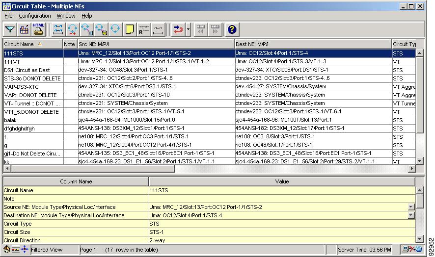
7.2.3 Viewing the Circuit Table
The Circuit table shows circuit information for all circuits that make up a topology. A circuit describes a fixed-size bandwidth pipe that is fully cross-connected from one user-defined source point (node, slot, or port) to a second user-defined destination point across some number of node-to-node optical spans (zero if the circuit is local to a single NE).
An endpoint can be an actual physical drop port (DS-1, DS-3, and so on) or an STS-n or VT1.5 channel in an optical line. A multicast circuit consists of circuit spans that have one source endpoint and a sequence of destination endpoints.
Figure 7-1 Circuit Table
Note
To launch the Circuit table, do any of the following:
•
•
•
Note
The following table describes the fields in the Circuit table.
Note
7.2.4 Creating Circuits Using the Circuit Wizard
The Create Circuit wizard (Configuration > Create Circuit) allows you to create circuits on CTC-based and CRS-1 NEs. Use the Create Circuit wizard to create an end-to-end circuit through a subnetwork. A subnetwork is defined as a set of NEs that are interconnected directly or indirectly through links known by CTM. CTM supports circuit provisioning across a heterogeneous network. Establish a circuit by specifying the A and Z termination points (TPs). You can create multiple circuits using the Create Circuit wizard; however, for VT tunnel circuits, the number you can create is limited by the bandwidth available on the VT tunnel being used. The maximum number of VT circuits that can be routed through a VT tunnel is 28.
Caution
Note
The following table describes the launch points and the expected behavior for the Circuit wizard.
The following table describes the various types of circuits that can be created. The type of circuit that you can create depends on the NEs that you select as the source and destination.
Table 7-6 Circuit Types that Can Be Created Using the Circuit Wizard
Create an STS (including Ethernet), VT, VT tunnel, or VT aggregation circuit
—
Creating an STS (Including Ethernet), STS-V, VT, VT-V, VT Tunnel, or VT Aggregation Circuit
Create a VCAT circuit
You can create VCAT circuits (STS-v, VT-v, VC_HO_PATH_VCAT_CIRCUIT, or VC_LO_PATH_VCAT_CIRCUIT).
Create a VC_HO_path circuit
You can create unidirectional or bidirectional, revertive or nonrevertive, high-order path circuits.
Create a VC_LO_path circuit
You can create unidirectional or bidirectional, revertive or nonrevertive, low-order path circuits.
Create a VC low path tunnel connection
—
Create a VC low path aggregation connection
—
Create a DWDM optical channel connection
—
Create a monitor circuit
Use the Circuit table to create new circuits from the CTM database and the associated cross-connections between NEs.
Create a unidirectional drop circuit
Use the Create Drop wizard to create a new protected or unprotected unidirectional circuit drop.
Create a G1000-4 circuit
Provision G1000-4 point-to-point circuits and Ethernet manual cross-connects.
Create an E-series circuit
Create these configurations and Ethernet manual cross-connects.
Create a BLSR DRI or MS-SPRing DRI circuit
—
Creating a BLSR DRI or MS-SPRing DRI Circuit Automatically
Note
Note
Caution
The following table describes the fields in the Create Circuit wizard for optical devices.
Table 7-7 Field Descriptions for the Create Circuit Wizard—Optical Devices
The navigation pane on the left side of the Create Circuit wizard tells you where you are in the process of creating the circuit. The list of tasks shown initially is the default list of all possible tasks. As you move through the circuit creation, you are taken to the appropriate task. You can use the navigation pane to jump quickly from one task to the next, or to an already visited task.
Using the navigation pane is faster than using the Back and Next buttons, because you can jump over multiple panes in one step versus clicking Back or Next and moving through the panes sequentially.
TipTipType
Select the type of circuit to create from the Type drop-down list.
Note
SONET and SDH circuits have different types. For SONET circuits, values are:
•
•
•
•
•
•
•
•
For SDH circuits, values are:
•
•
•
•
•
•
•
•
Note
Number of Circuits
Enter the number of circuits that you want to create.
Auto-Ranged
If you are creating multiple circuits with the same slot and sequential port numbers, you can use Auto-Ranged to create the circuits automatically. The Auto-Ranged check box is checked automatically for multiple circuits.
For VC3 Port Grouping Only
(For SDH tunnel circuits only) Check this check box to create VC low-order path tunnels for port grouping. Using these circuits, VC4 tunnels can transport VC3 signal rates. Three ports form a port group. For example, in one E3 or one DS3i card, there are four port groups: Ports 1-3 = PG1, ports 4-6 = PG2, ports 7-9 = PG3, and ports 10-12 = PG4.
(fields depend on the circuit type)
Name
Enter a unique name for the new circuit. The circuit name is a free-format string, up to 48 ASCII characters. For VCAT circuits, the maximum circuit name length is 44 ASCII characters.
Circuit Alias
Enter a unique alias name for the new circuit. The alias name can contain alphanumeric characters. It also supports international character sets.
Description
Enter a description for the new circuit, up to 256 ASCII characters.
Type
(Read-only) Indicates the type of circuit that you selected in the Type pane.
Note
Size Group
(OCHNC circuits only) Choose a size for the group that you want to provision.
Size
Specify the size of the circuit. SONET circuit sizes are VT 1.5, VT2, STS-1, STS-3c, STS-6c, STS-9c, STS-12c, STS-18c, STS-24c, STS-36c, STS-48c, and STS-192c.
SDH circuit sizes are VC11, VC12, VC3, VC4, VC4-2c, VC4-3c, VC4-4c, VC4-6c, VC4-8c, VC4-12c, VC4-16c, and VC4-64c.
If OCHNC is selected in Type, the OCHNC circuit size is Equipment Not Specific.
For supported circuit sizes on Ethernet cards, see Cisco ONS 15454 Reference Manual, available at http://www.cisco.com/univercd/cc/td/doc/product/ong/15400/index.htm.
For single-card EtherSwitch, only STS-1, STS-3c, STS-6c, and STS-12c apply. For multicard EtherSwitch, only STS-1, STS-3c, and STS-6c apply.
Note
OCHNC Wavelength
If OCHNC is selected in Type, the wavelength of the OCHNC is selected here. If OCHNC is not selected in Type, this option is not available.
Band
(OCHNC circuits only) Choose the band you want to provision.
Use OCHNC Direction
Choose whether or not to specify the OCHNC direction. Select the check box to allow you to specify the circuit direction (for NEs up to and including R6.0) in the OCHNC Direction drop-down list. If the check box is unchecked (for R7.0 NEs) the OCHNC Direction drop-down list is disabled.
Channel Group
Choose the channel group you want to provision (OCHNC circuits only).
OCHCC Wavelength
If OCHCC is selected in Type, the wavelength of the OCHCC is selected here. If OCHCC is not selected in Type, this option is not available.
OCHNC Direction
If OCHNC is selected in Type, the east-to-west or west-to-east direction of the OCHNC is selected here. If OCHNC is not selected in Type, this option is not available.
Bidirectional
Check this check box to create a two-way circuit; uncheck it to create a one-way circuit.
State
Select an administrative state for the new circuit. SONET and SDH circuits have different values. For SONET circuits, values are:
•
•
•
•
For SDH circuits, corresponding values are:
•
•
•
•
Apply to Source/Destination Ports, If Allowed
Check this check box to apply the selected state to the source and destination ports.
(available for OCHCC circuit type only)
Protected
Check this check box to specify that circuit endpoints have to be selected only from cards that have embedded splitter-type protection.
(available for OCHCC circuit type only)
G.709 OTN
Disables or enables the G.709 OTN feature. Check this check box to filter the list of circuits to display only G.709 OTN-compatible circuits.
FEC
Disables or enables forward error correction.
OTN must be enabled before you can enable FEC.
SF BER
Allows you to enter the signal fail bit error rate.
SD BER
Allows you to select the signal degrade bit error rate.
Mapping
The card can perform multiplexing per ITU-T G.709. The ODUk (client SONET/SDH payload) can be mapped to the Optical Channel (OTUk) either asynchronously (asynch mapping) or synchronously (synch mapping) with this setting.
Customer ID
Optional text field that displays the customer ID of the circuit. The customer ID can contain 0 to 256 alphanumeric and special characters.
Service ID
Optional text field that displays the service ID of the selected circuit. The service ID can contain 0 to 256 alphanumeric and special characters.
Symmetric
Check this check box to create a symmetric VCAT circuit.
Member Size
Select a size for each VCAT member.
Number of Members
Specify the number of members to be configured for the VCAT circuit.
Mode
Choose the protection mode for the VCAT circuit:
•
•
•
Protected Drops (Non-Ethernet)
Specify whether protected drops are indicated. If selected, this option restricts the set of displayed source or destination termination points to those in 1:1, 1:n, or 1+1 protection groups.
Provision Working Go and Return on Primary Path
Check this check box to provision SNCP/UPSR protection routes in a Go and Return fashion as detailed in ITU-T G.841, to avoid too long a delay on another direction of traffic. This feature applies only to bidirectional UPSR/SNCP circuits. Unidirectional UPSR/SNCP circuits are not affected and the shortest path to the destination is always used as the working path.
Revertive
Specify whether traffic is reverted back to its original path when the conditions that diverted the circuit to the protect path are repaired. If you do not choose Revertive, traffic remains on the protect path.
Reversion Time
Specify the amount of time (in minutes) after which traffic reverts back to the original working path when conditions that caused the switch are cleared. The range is from 0.5 to 12.0 minutes. The Cisco default is 5 minutes.
SF Threshold (for SONET circuits only)
Set the UPSR path-level signal failure (SF) threshold.
Note
SD Threshold (for SONET circuits only)
Set the UPSR path-level signal degrade (SD) threshold.
Note
Switch on PDI-P (for SONET circuits only)
Specify whether traffic should switch based on a received STS payload defect indication.
Note
(fields depend on the NE selected and the circuit type)
Use Secondary Source
(For DRI, open UPSR, and open-ended SNCP circuits) Check this check box to define a secondary source. Then, specify the slot, port, STS, DS-1, or VT for the secondary source.
NE ID
Select from the list of available NE IDs to specify the source NE ID.
Subnetwork ID
(Read-only) Displays the ID of the subnetwork associated with the circuit source.
Slot
Specify the source slot (only for SONET/SDH circuits).
Port
Specify the source port (only for SONET/SDH circuits).
STS
(For SONET circuits) Specify the source STS.
VT
(For SONET circuits) Specify the source VT.
DS1
(For SONET circuits) Specify the source DS-1.
VC4
(For SDH circuits) Specify the source VC4.
VC3
(For SDH circuits) Specify the source VC3.
VC11
(For SDH circuits) Specify the source VC11.
VC12
(For SDH circuits) Specify the source VC12.
TUG3
(For SDH circuits) Specify the source TUG3.
TUG2
(For SDH circuits) Specify the source TUG2.
(fields depend on the NE selected and the circuit type)
Use Secondary Destination
(For DRI, open UPSR, and open-ended SNCP circuits) Check this check box to define a secondary destination. Then, specify the slot, port, STS, DS-1, or VT for the secondary destination.
NE ID
Select from the list of available TPs to specify the destination TP.
Subnetwork ID
(Read-only) Displays the ID of the subnetwork associated with the circuit destination.
Slot
(For SONET and SDH circuits) Specify the destination slot.
Port
(For SONET and SDH circuits) Specify the destination port.
STS
(For SONET circuits) Specify the destination STS.
VT
(For SONET circuits) Specify the destination VT.
DS1
(For SONET circuits) Specify the destination DS-1.
VC4
(For SDH circuits) Specify the destination VC4.
VC3
(For SDH circuits) Specify the destination VC3.
VC11
(For SDH circuits) Specify the destination VC11.
VC12
(For SDH circuits) Specify the destination VC12.
TUG3
(For SDH circuits) Specify the destination TUG3.
TUG2
(For SDH circuits) Specify the destination TUG2.
Route Automatically
Enable or disable automatic route selection. If enabled, CTM automatically determines the route for the circuit. Alternately, you can disable automatic route selection and manually route the circuit where you specify all the intermediate hops on a hop-by-hop basis (up to 64 hops per circuit). You can manually route the circuit using either one of the following views:
•
•
Note
Using Required Nodes/Links
(Available only if Route Automatically is checked) If checked, CTM automatically routes the circuit through the required nodes and/or links. There are two ways you can specify the required nodes and links. Choose one of the following:
•
•
Review Route Before Creation
(Available only if Route Automatically is checked) Check this check box to review the route before it is created.
VT-DS3 Mapped Conversion
(Available only if Route Automatically is checked) If checked, you can route the circuit using the DS3XM12 card. Not applicable for data cards (ML-series and CE-100T-8 cards).
Time Slot Restriction
If checked, you can enter an STS/VC4 value (to be used end-to-end) that CTM will use to automatically determine the route for the circuit. Circuit creation is rejected if the same STS/VC4 is not available end-to-end. If circuit creation is rejected, you can try circuit creation again using different values. The valid range you can enter is from 1 to 192 for SONET, or 1 to 64 for SDH networks. The default value is -1, indicating that STS routing is not applicable.
Note
Note
Common Fiber Routing
(For VCAT circuits) Click this radio button to route each member circuit on the same fiber.
Split Routing
(For VCAT circuits) Click this radio button to route member circuits on separate paths.
Member Preferences
(For VCAT circuits) Specify the following information for member circuits:
•
•
•
•
–
–
–
•
•
Fully Protected Path
If selected, CTM ensures that the circuit is fully protected. You can provision the circuit in a UPSR DRI topology by checking the Dual Ring Interconnect check box. Alternately, if the circuit must pass across unprotected links, CTM creates a primary and alternate circuit route (virtual UPSR) based on the following node diversity specifications:
•
•
•
Protection Channel Access
To route the circuit on a BLSR protection channel, if available, uncheck the Fully Protected Path check box, and check the Protection Channel Access check box.
Dual Ring Interconnect
If you selected Fully Protected Path and the circuit will be routed on a DRI, check the Dual Ring Interconnect check box.
Note
Diverse Shared Risk Link Group (SRLG)
If checked, fully protected circuits will be routed through working and protected links that do not share risk groups.
(available only if VT-DS3 Mapped Conversion is checked)
NE ID
Select from the list of available NE IDs to specify the source NE ID.
Subnetwork ID
(Read-only) Displays the ID of the subnetwork associated with the circuit source.
Slot
Specify the source slot that contains the DS3XM card.
DS3 Mapped STS
Choose Circuit Source or Circuit Dest.
(available only for VT and VC LO path circuits)
VT/VC LO Tunnel on Transit Nodes
This option is available if the VT or VC circuit passes through a node that does not have a low-order tunnel, or if an existing low-order tunnel is full. Low-order tunnels allow VT/VC circuits to pass through NEs without consuming low-order cross-connect card resources. In general, creating tunnels is a good idea if you are creating many low-order circuits from the same source and destination.
VT Aggregation Point (VAP)/VC LO Aggregation Point (LAP)
(For SONET) This option is available if you are creating a VT1.5 circuit to a DS-1, EC-1, DS3XM-6; or an OC-N port on a BLSR, 1+1, or Unprotected node. A VAP allows VT1.5 circuits to be routed through a node using one STS connection on the cross-connect card matrix rather than multiple connections on the VT1.5 matrix.
(For SDH) This option is available if you are creating a VC12 circuit to an STM-N port for handoff to non-SDH networks or equipment, such as an IOF, switch, or DACS. A LAP allows low-order circuits to be routed through a node using one VC4 connection on the cross-connect card high-order matrix rather than multiple connections on the low-order matrix.
Circuit Source is STS/VC4 Grooming Node
Creates the VAP or LAP on the VT or VC circuit source node. This option is available only if the VT circuit originates on a DS-1, EC-1, DS3XM-6, or OC-N card, or if the VC circuit originates on an STM-N card.
Circuit Destination is STS/VC4 Grooming Node
Creates the VAP or LAP on the VT or VC circuit destination node. This option is available only if the VT circuit terminates on a DS-1, EC-1, DS3XM-6, or OC-N card, or if the VC circuit terminates on an STM-N card.
None
Choose this option if you do not want to create a low-order tunnel or a VAP/LAP. This is the only available option if CTM cannot create a low-order tunnel or VAP/LAP.
(available only for Ethernet cards or EtherGroups)
VLANs
Select from the list of available VLANs to associate an existing VLAN to the circuit. If the Circuit VLANs list is empty, CTM assigns the default VLAN.
To create a new VLAN, click the New VLAN button. Enter a unique VLAN name and ID. The VLAN ID must be an integer greater than 1 but less than 4093. Click OK; then, click OK in the Successfully created VLAN confirmation dialog box. The new VLAN appears in the list of VLANs. The list is ordered alphanumerically by VLAN name, where numbers precede letters and uppercase letters precede lowercase ones.
Note
Enable Spanning Tree
Check this check box to enable spanning tree protection for the circuit. This option is disabled for intranode and multicard Ethernet circuits.
Map view
Allows you to tag a node in the map view as a VT or VC LO grooming node. By clicking a node icon, the node is automatically tagged as a VT or VC LO grooming node.
(available if the Route Automatically check box is unchecked and the Graphical radio button is selected)
VCAT Member Number
(For VCAT circuits) Use the drop-down list to select route constraints for each member circuit.
Map view
Displays the NEs that are available in the subnetwork for circuit creation. Map view also indicates the source (and secondary source, if applicable) and destination (and secondary destination, if applicable) NEs selected for circuit creation. The map view is used to manually route the circuit from the source to the destination specified by the addition of the links selected.
Use the right-click menu options to navigate within the map view:
•
•
•
•
•
Available Spans
Select a link on the map view (related to the selected node) and its corresponding details are displayed in the Available Spans pane. Click Add to move the spans to the Selected Spans field. The newly added link appears in blue on the map view.
Selected Spans
Select one or more spans and click Remove to remove them from the Selected Spans field. The removed link appears in green to indicate its unselected state.
Note
Links/Nodes tab
Select the links/nodes in the graphic to populate the selected node field.
BLSR DRI Nodes or MS-SPRing DRI Nodes tab
(For BLSR DRI or MS-SPRing DRI circuits) Click the Add button to open the BLSR/MS-SPRing DRI dialog box, which allows you to provide primary and secondary pairs for traditional and nontraditional DRI circuits. Also specify ring and path options for the first and second rings. Click Remove to remove a DRI node from the list.
(available if the Route Automatically check box is unchecked and the Textual radio button is selected)
Src NE ID
Displays the circuit source NE.
Dest NE ID
Displays the circuit destination NE.
Current NE ID
Displays the currently selected NE.
Adj NE ID
Displays all the NEs that are adjacent to the currently selected NE.
Available Links
Lists all links between the currently selected and adjacent NEs. Select a link from the drop-down list.
Available Spans
After you select a link from the Available Links drop-down list, its corresponding details are displayed in the Available Spans pane. Click Add to move the spans to the Selected Spans field.
Selected Spans
Select one or more spans and click Remove to remove them from the Selected Spans field.
Next Hop
Click Next Hop to specify the next intermediate hop.
Reset
Click Reset to reset all hop information to the default values.
Alternate Route
Click Alternate Route to specify hop information for the alternate circuit route.
(applicable only if the Using Required Nodes/Links check box is checked)
VCAT Member Number
(For VCAT circuits) Use the drop-down list to select route constraints for each member circuit.
Map view
(For graphical manual provisioning) Displays the NEs that are available in the subnetwork for circuit creation. This pane also indicates the source (and secondary source, if applicable) and destination (and secondary destination, if applicable) NEs selected for circuit creation. The map view is used for the inclusion and exclusion of links or nodes during the specification of route constraints. The included nodes are shown in blue and the excluded links are shown in magenta.
Use the right-click menu options to navigate within the map view:
•
•
•
•
Src NE ID
(For textual manual provisioning) Displays the circuit source NE.
Dest NE ID
(For textual manual provisioning) Displays the circuit destination NE.
Nodes
(For textual manual provisioning) Select Nodes if you want to add nodes to your circuit route.
Links
(For textual manual provisioning) Select Links if you want to add links to your circuit route.
Current NE ID
(For textual manual provisioning) Displays the currently selected NE.
Adj NE ID
(For textual manual provisioning) Displays all the NEs that are adjacent to the currently selected NE.
Available Links
(For textual manual provisioning) Lists all links between the currently selected and adjacent NEs. Select a link from the drop-down list.
Select Nodes
(For textual manual provisioning) Lists all nodes related to the currently selected NE. Select a node from the list.
Selected Node/Link
Displays the currently selected NE or link.
Included Links/Nodes
Displays the list of links or nodes that are included in the route.
Excluded Links/Nodes
Displays the list of links or nodes that are excluded from the route.
(applicable only if the Review Route before creation check box is checked)
VCAT Member Number
(For VCAT circuits) Use the drop-down list to view the route chosen for each member circuit.
Map view
Displays the NEs that are available in the subnetwork for circuit creation. This pane also indicates the source (and secondary source, if applicable) and destination (and secondary destination, if applicable) NEs selected for circuit creation. The map view is used for the inclusion and exclusion of links or nodes during the specification of route constraints. The included nodes are shown in blue and the excluded links are shown in magenta.
Use the right-click menu options to navigate within the map view:
•
•
•
•
Review Route
Displays the NEs that are available in the subnetwork for circuit creation. This pane also indicates the source (and secondary source, if applicable) and destination (and secondary destination, if applicable) NEs selected for circuit creation. The map view displays information about the spans selected during autorouting in the subnetwork. The selected spans are shown in blue. When you select a span, its corresponding details are displayed in the Selected Span pane. The circuit summary displays the total hops and the cost for working and protect paths for the routed circuit.
Source NE ID
Displays the ID of the NE selected as the source node.
Destination NE ID
Displays the ID of the NE selected as the destination node.
Included Spans
If you enabled automatic route selection in the Routing Preferences pane, CTM automatically selects spans to route the circuit. This field lists all the spans that the CTM server selected automatically.
Selected Span
Displays detailed information about the span selected in the Included Spans list.
Circuit Summary
Summarizes the selections you made in the wizard panes. To change the circuit summary, click Back and change your selection(s).
The following table describes the fields in the Create Circuit wizard for CRS-1 devices.
7.2.4.1 Creating an STS (Including Ethernet), STS-V, VT, VT-V, VT Tunnel, or VT Aggregation Circuit
Step 1
Step 2
Step 3
Step 4
•
•
•
•
For a single-card EtherSwitch, only STS-1, STS-3c, STS-6c, and STS-12c apply. For a multicard EtherSwitch, only STS-1, STS-3c, and STS-6c apply.
Valid circuit sizes for an ML-series circuit are STS-1, STS-3c, STS6c, STS-9c, STS-12c, and STS-24c.
•
•
•
–
–
–
–
•
•
•
Note
•
–
–
–
–
–
•
–
–
Step 5
•
•
•
Note
Step 6
•
•
•
Note
Step 7
a.
Note
b.
c.
Step 8
a.
•
•
b.
•
•
c.
d.
e.
Note
f.
g.
•
•
•
•
Step 9
•
•
•
Step 10
•
•
Step 11
a.
•
•
•
•
•
b.
c.
Note
d.
Step 12
a.
•
•
•
•
•
•
•
b.
c.
d.
Step 13
a.
b.
c.
d.
e.
f.
g.
Step 14
a.
b.
c.
d.
e.
f.
g.
h.
i.
Step 15
a.
b.
c.
•
•
•
•
Note
Step 16
Caution
7.2.4.2 Creating a VCAT Circuit
This section describes how to create VCAT circuits (STS-v, VT-v, VC_HO_PATH_VCAT_CIRCUIT, or VC_LO_PATH_VCAT_CIRCUIT). For SDH nodes, only VC_HO_PATH is supported for VCAT circuits.
VCAT circuits are supported on the following cards:
•
•
•
•
•
Note
Step 1
Step 2
Note
Step 3
•
•
•
•
•
•
•
•
•
•
•
•
–
–
–
–
–
•
•
Note
Step 4
Step 5
Step 6
Step 7
Step 8
a.
•
•
b.
•
•
c.
d.
Note
e.
f.
•
•
•
•
g.
•
•
•
•
Note
Step 9
a.
•
•
•
•
•
b.
c.
d.
•
•
e.
f.
g.
h.
Note
i.
Step 10
a.
•
•
•
•
•
•
•
b.
c.
d.
Step 11
a.
b.
c.
d.
e.
f.
g.
h.
i.
Step 12
a.
b.
c.
d.
e.
f.
g.
h.
i.
Step 13
Note
a.
b.
c.
d.
Step 14
7.2.4.3 Creating a VC_HO_Path_Circuit
The E1-N-14 card, STM-N cards, and Ethernet cards all use high-order path circuits. You can create unidirectional or bidirectional, revertive or nonrevertive, high-order path circuits. CTM can route the circuits automatically, or you can route them manually. The E3-12 and DS3i-N-12 cards use VC low-order path tunnels.
Step 1
Step 2
Step 3
Step 4
•
•
•
•
•
•
•
•
•
Note
•
–
–
–
–
–
•
•
Step 5
Step 6
Step 7
Step 8
Step 9
a.
•
•
b.
•
•
c.
d.
Note
e.
•
•
•
f.
•
•
•
•
Step 10
a.
•
•
•
•
•
b.
c.
d.
•
•
e.
f.
g.
h.
Note
i.
Step 11
a.
•
•
•
•
•
•
•
b.
c.
d.
Step 12
a.
b.
c.
d.
e.
f.
g.
h.
Step 13
a.
b.
c.
d.
e.
f.
g.
h.
i.
Step 14
a.
b.
c.
Step 15
7.2.4.4 Creating a VC_LO_Path_Circuit
Step 1
Step 2
Step 3
Step 4
•
•
•
•
•
•
•
•
•
Note
•
–
–
–
–
–
•
•
Step 5
Step 6
Step 7
Step 8
Step 9
a.
•
•
b.
•
•
c.
d.
Note
e.
•
•
•
f.
•
•
•
•
Step 10
a.
b.
•
•
c.
Step 11
•
•
Step 12
a.
•
•
•
•
•
b.
c.
d.
•
•
e.
f.
g.
h.
Note
i.
Step 13
a.
•
•
•
•
•
•
•
b.
c.
d.
Step 14
a.
b.
c.
d.
e.
f.
g.
h.
Step 15
a.
b.
c.
d.
e.
f.
g.
h.
i.
Step 16
a.
b.
c.
Step 17
7.2.4.5 Creating a VC_LO_Path_Tunnel
Step 1
Step 2
Step 3
Step 4
•
•
•
•
•
•
•
•
•
•
–
–
–
–
–
•
•
Step 5
Step 6
Step 7
Step 8
Step 9
Step 10
•
•
•
Step 11
•
•
•
Step 12
a.
•
•
•
•
•
b.
c.
d.
•
•
e.
f.
g.
h.
Note
i.
Step 13
a.
•
•
•
•
•
•
•
b.
c.
d.
Step 14
a.
b.
c.
d.
e.
f.
g.
h.
Step 15
a.
b.
c.
d.
e.
f.
g.
h.
i.
Step 16
a.
b.
c.
Step 17
7.2.4.6 Creating a VC_LO_Path_Aggregation Circuit
Step 1
Note
Step 2
Step 3
Step 4
•
•
•
•
•
•
•
•
•
–
–
–
–
–
•
•
Step 5
Step 6
Step 7
Step 8
Step 9
a.
•
•
b.
•
•
c.
d.
Note
e.
•
•
•
f.
•
•
•
•
Step 10
a.
•
•
•
•
•
b.
c.
d.
•
•
e.
f.
g.
h.
Note
i.
Step 11
a.
•
•
•
•
•
•
•
b.
c.
d.
Step 12
a.
b.
c.
d.
e.
f.
g.
h.
Step 13
a.
b.
c.
d.
e.
f.
g.
h.
i.
Step 14
a.
b.
c.
Step 15
7.2.4.7 Creating a DWDM OCHNC
Step 1
Step 2
Step 3
Step 4
•
•
•
•
•
•
•
•
•
•
•
•
Note
Step 5
Note
Step 6
Note
Step 7
Caution
7.2.4.8 Creating a DWDM OCHCC
CTM allows you to create OCHCC circuits between two CRS-1 or ONS 15454 MSTP products. ONS 15454 MSTP is a DWDM optical product designed to provide transparent, reliable, and manageable transport capacity to Cisco Metro optical products such as ONS 15454 MSPP, ONS 15530, and ONS 15540. OCHCC increases ONS 15454 MSTP platform functionalities, providing the possibility to create a new E2E circuit layer with transponder/muxponder client ports or ITU-T line card trunk ports as endpoints.
OCHCC can be created in a peer-to-peer setup, where the trunk ports are directly connected by a routable virtual link, or in an MSTP setup, where the circuit is routed through a tunnel circuit, which is created between the trunk ports (OCH trail tunnel), and which in practice contains an OCHNC-type circuit.
OCHCC circuit creation is supported on CRS-1 NEs with the ITU Physical Layer Interface Modules (PLIMs) on 10 GE C-band and OC768 interfaces. OCHCC circuit creation between CRS-1 NEs is supported in the following scenarios:
•
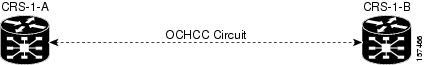
If there is more than one ONS 15454 MSTP NE connection between CRS-1 peers, an OCHNC circuit is created automatically between the ONS 15454 MTSP NEs. The following figure shows a graphical representation of this scenario.
Figure 7-2 CRS-1 DWDM OCHCC Circuit Creation—Scenario 1
•
Figure 7-3 CRS-1 DWDM OCHCC Circuit Creation—Scenario 2
Note
Step 1
Step 2
Step 3
Step 4
•
•
•
•
•
•
•
•
•
•
•
•
•
•
•
•
•
•
•
•
Step 5
Step 6
Note
Step 7
Step 8
Caution
7.2.4.9 Creating a Monitor Circuit—CTC-Based NEs
Use the Create Monitor Circuit wizard to create a new monitor circuit on CTC-based NEs.
Note
Step 1
Step 2
Step 3
Step 4
Step 5
Step 6
•
•
•
Step 7
Step 8
Step 9
a.
•
•
b.
•
•
c.
d.
Note
e.
•
•
•
f.
•
•
•
•
Step 10
a.
•
•
•
•
•
b.
c.
d.
•
•
e.
f.
g.
h.
Note
i.
Step 11
a.
•
•
•
•
•
•
•
b.
c.
d.
Step 12
a.
b.
c.
d.
e.
f.
g.
h.
Step 13
a.
b.
c.
d.
e.
f.
g.
h.
i.
Step 14
a.
b.
c.
Step 15
Step 16
Step 17
7.2.4.10 Creating a Unidirectional Drop Circuit—CTC-Based NEs
Use the Create Drop wizard to create a new protected or unprotected unidirectional circuit drop. A circuit drop can also be created on bidirectional Ethernet circuits. For all other types of circuits, drop creation is possible only on unidirectional circuits.
Step 1
Step 2
Step 3
Step 4
Step 5
Step 6
Note
•
•
•
•
•
•
•
•
•
•
•
•
•
–
–
–
–
For SDH circuits, values are:
–
–
–
–
•
Step 7
The Routing Preferences pane in the Create Drop wizard is similar to the Routing Preferences pane in the Create Circuit wizard, except that for a drop, the Fully Protected Path check box is unchecked (disabled) for Ethernet circuits and unchecked (enabled) for all other circuits. You can check or uncheck the Fully Protected Path check box. If the existing circuit is protected and during drop creation you check or uncheck the Fully Protected Path check box, an error message is returned after you click Next. You must change the protection option if the error message indicates that all drops must have the same protection.
Subsequent panes in the Create Drop wizard are identical to the panes in the Create Circuit wizard (see Table 7-7).
Step 8
Step 9
Step 10
7.2.4.11 Creating G1000-4 Circuits
This section explains how to provision G1000-4 point-to-point circuits and Ethernet manual cross-connects. Ethernet manual cross-connects allow you to cross-connect individual Ethernet circuits to an STS channel on the ONS 15454 SONET or ONS 15454 SDH optical interface and to bridge non-ONS SONET network segments.
7.2.4.11.1 G1000-4 Point-to-Point Ethernet Circuits
G1000-4 cards support point-to-point circuit configuration. Provisionable circuit sizes are STS-1, STS-3c, STS-6c, STS-9c, STS-12c, STS-24c, and STS-48c. Each Ethernet port maps to a unique STS circuit on the SONET side of the G1000-4.
The G1000-4 card supports any combination of up to four circuits from the list of valid circuit sizes; however, the circuit sizes can add up to no more than 48 STSs. Due to hardware constraints, the initial release of the G1000-4 card (software release 3.2) imposes additional restrictions on the combinations of circuits that can be dropped onto a G1000-4 card. These restrictions are transparently enforced by the ONS 15454 SONET and ONS 15454 SDH, so there is no need to keep track of restricted circuit combinations.
•
•
•
Caution
Caution
Step 1
Step 2
a.
b.
c.
Step 3
Note
Step 4
Step 5
Step 6
Step 7
Note
Caution
Step 8
•
•
Step 9
Step 10
Step 11
Step 12
Step 13
Step 14
Step 15
Step 16
Step 17
Step 18
a.
•
•
b.
•
•
c.
d.
Note
e.
•
•
•
f.
•
•
•
•
Step 19
a.
•
•
•
•
•
b.
c.
d.
•
•
e.
f.
g.
h.
Note
i.
Step 20
a.
•
•
•
•
•
•
•
b.
c.
d.
Step 21
a.
b.
c.
d.
e.
f.
g.
h.
Step 22
a.
b.
c.
d.
e.
f.
g.
h.
i.
Step 23
a.
•
•
•
•
b.
c.
Step 24
Step 25
Note
7.2.4.11.2 G1000-4 Manual Cross-Connects
ONS 15454 SONET and ONS 15454 SDH NEs require end-to-end CTC visibility between nodes for normal provisioning of Ethernet circuits. When equipment from other vendors is placed between the ONS 15454 SONET and ONS 15454 SDH, equipment based on Open System Interconnection/Target Identifier Address Resolution Protocol (OSI/TARP) does not allow tunneling of the ONS 15454 SONET or ONS 15454 SDH TCP/IP-based data communications channel (DCC). To circumvent a lack of continuous DCC, the Ethernet circuit must be manually cross-connected to an STS channel riding through the non-ONS network. This allows an Ethernet circuit to run from ONS node to ONS node while utilizing the non-ONS network.
Note
Step 1
Step 2
a.
b.
c.
Step 3
Note
Step 4
Step 5
Step 6
Step 7
Step 8
•
•
Step 9
Step 10
Step 11
Step 12
Step 13
Step 14
Step 15
Step 16
Note
Step 17
a.
•
•
b.
•
•
c.
d.
Note
e.
•
•
•
f.
•
•
•
•
Step 18
a.
•
•
•
•
•
b.
c.
d.
•
•
e.
f.
g.
h.
Note
i.
Step 19
a.
•
•
•
•
•
•
•
b.
c.
d.
Step 20
a.
b.
c.
d.
e.
f.
g.
h.
Step 21
a.
b.
c.
d.
e.
f.
g.
h.
i.
Step 22
a.
•
•
•
•
b.
c.
Step 23
Step 24
Step 25
Note
Caution
7.2.4.12 Creating E-Series Circuits
Ethernet circuits can link ONS nodes through point-to-point, shared packet ring, or hub-and-spoke configurations. Two nodes usually connect with a point-to-point configuration. More than two nodes usually connect with a shared packet ring configuration or a hub-and-spoke configuration. This section includes procedures for creating these configurations and also explains how to create Ethernet manual cross-connects. Ethernet manual cross-connects allow you to cross-connect individual Ethernet circuits to an STS channel on the ONS 15454 SONET or ONS 15454 SDH optical interface and also to bridge non-ONS SONET network segments.
Note
Note
7.2.4.12.1 Provisioning E-Series EtherSwitch Point-to-Point Ethernet Circuits (Multicard, Single-Card, or Port-Mapped)
The ONS 15327, ONS 15454 SONET, and ONS 15454 SDH can set up a point-to-point (straight) Ethernet circuit as single-card or multicard. Multicard EtherSwitch is limited to STS-6c of bandwidth between two Ethernet circuit points, but allows you to add nodes and cards and create a shared packet ring. Single-card EtherSwitch allows a full STS-12c of bandwidth between two Ethernet circuit points.
Step 1
Step 2
Step 3
Step 4
a.
b.
c.
Step 5
a.
b.
Step 6
a.
b.
Step 7
Step 8
Step 9
a.
b.
c.
Step 10
Note
Step 11
Step 12
Step 13
•
•
Step 14
Step 15
•
•
Step 16
a.
b.
c.
d.
Step 17
a.
b.
c.
d.
Step 18
a.
b.
c.
Note
d.
e.
Note
Step 19
Step 20
Step 21
a.
•
•
b.
•
•
c.
d.
Note
e.
•
•
•
f.
•
•
•
•
Step 22
a.
•
•
•
•
•
b.
c.
d.
•
•
e.
f.
g.
h.
Note
i.
Step 23
a.
•
•
•
•
•
•
•
b.
c.
d.
Step 24
a.
b.
c.
d.
e.
f.
g.
h.
Step 25
a.
b.
c.
d.
e.
f.
g.
h.
i.
Step 26
a.
•
•
•
•
•
b.
c.
Step 27
Step 28
7.2.4.12.2 Provisioning E-Series Shared Packet Ring Ethernet Circuits
Step 1
Step 2
Step 3
Step 4
Step 5
Step 6
Step 7
Step 8
Step 9
a.
b.
c.
Step 10
Note
Step 11
Step 12
Step 13
Step 14
Note
Step 15
Step 16
Step 17
Step 18
Step 19
Step 20
a.
b.
c.
Note
d.
e.
Step 21
Step 22
a.
•
•
b.
•
•
c.
d.
Note
e.
•
•
•
f.
•
•
•
•
Note
Step 23
a.
•
•
•
•
•
b.
c.
d.
•
•
e.
f.
g.
h.
Note
i.
Step 24
a.
•
•
•
•
•
•
•
b.
c.
d.
Step 25
a.
b.
c.
d.
e.
f.
g.
h.
Step 26
a.
b.
c.
d.
e.
f.
g.
h.
i.
Step 27
a.
b.
c.
Step 28
Step 29
7.2.4.12.3 Provisioning E-Series Hub-and-Spoke Ethernet Circuits
This section provides steps for creating a hub-and-spoke Ethernet circuit configuration. The hub-and-spoke configuration connects point-to-point circuits (the spokes) to an aggregation point (the hub). In many cases, the hub links to a high-speed connection and the spokes are Ethernet cards.
Step 1
Step 2
Step 3
Step 4
Step 5
Step 6
a.
b.
c.
Step 7
Note
Step 8
Step 9
Step 10
Step 11
Step 12
Step 13
Step 14
Step 15
Step 16
a.
b.
c.
Note
d.
e.
Step 17
Step 18
a.
•
•
b.
•
•
c.
d.
Note
e.
•
•
•
f.
•
•
•
•
Step 19
a.
•
•
•
•
•
b.
c.
d.
•
•
e.
f.
g.
h.
Note
i.
Step 20
a.
•
•
•
•
•
•
•
b.
c.
d.
Step 21
a.
b.
c.
d.
e.
f.
g.
h.
Step 22
a.
b.
c.
d.
e.
f.
g.
h.
i.
Step 23
a.
•
•
•
•
•
b.
c.
Step 24
Step 25
Step 26
7.2.4.12.4 E-Series Ethernet Manual Cross-Connects
ONS 15327, ONS 15454 SONET, and ONS 15454 SDH NEs require end-to-end CTC visibility between nodes for normal provisioning of Ethernet circuits. When equipment from other vendors is positioned between ONS 15327, ONS 15454 SONET, or ONS 15454 SDH NEs, equipment based on OSI/TARP does not allow tunneling of the ONS 15327, ONS 15454 SONET, or ONS 15454 SDH TCP/IP-based DCC. To circumvent this lack of continuous DCC, the Ethernet circuit must be manually cross-connected to an STS channel riding through the non-ONS network. This allows an Ethernet circuit to run from ONS node to ONS node by utilizing the non-ONS network.
Note
7.2.4.12.5 Provisioning a Single-Card EtherSwitch Manual Cross-Connect
Step 1
Step 2
Step 3
Step 4
Step 5
a.
b.
c.
Step 6
Note
Step 7
Step 8
Step 9
Step 10
Step 11
Step 12
Step 13
Step 14
Step 15
Note
Step 16
a.
b.
c.
Note
d.
e.
Step 17
Step 18
a.
•
•
b.
•
•
c.
d.
Note
e.
•
•
•
f.
•
•
•
•
Step 19
a.
•
•
•
•
•
b.
c.
d.
•
•
e.
f.
g.
h.
Note
i.
Step 20
a.
•
•
•
•
•
•
•
b.
c.
d.
Step 21
a.
b.
c.
d.
e.
f.
g.
h.
Step 22
a.
b.
c.
d.
e.
f.
g.
h.
i.
Step 23
a.
•
•
•
•
•
b.
c.
Step 24
Step 25
Step 26
Note
Caution
7.2.4.12.6 Provisioning an E-Series Multicard EtherSwitch Manual Cross-Connect
Step 1
Step 2
Step 3
Step 4
Step 5
Step 6
a.
b.
c.
Step 7
Note
Step 8
Step 9
Step 10
Step 11
Step 12
Step 13
Step 14
Step 15
Note
Step 16
a.
b.
c.
Note
d.
e.
Step 17
Step 18
a.
•
•
b.
•
•
c.
d.
Note
e.
•
•
•
f.
•
•
•
•
Step 19
a.
•
•
•
•
•
b.
c.
d.
•
•
e.
f.
g.
h.
Note
i.
Step 20
a.
•
•
•
•
•
•
•
b.
c.
d.
Step 21
a.
b.
c.
d.
e.
f.
g.
h.
Step 22
a.
b.
c.
d.
e.
f.
g.
h.
i.
Step 23
a.
•
•
•
•
•
b.
c.
Step 24
Step 25
Step 26
Step 27
Step 28
Step 29
Step 30
Step 31
Step 32
Step 33
Note
Caution
7.2.4.13 Creating a BLSR DRI or MS-SPRing DRI Circuit Automatically
The BLSR/MS-SPRing DRI feature allows you to provision a circuit in a DRI topology to provide the required protection when transitioning traffic between two rings, where at least one ring is a BLSR or MS-SPRing.
Step 1
Step 2
Step 3
Step 4
•
•
•
•
•
•
•
•
•
Note
•
–
–
–
–
–
•
•
Step 5
Step 6
Step 7
Step 8
Step 9
a.
•
•
Check the Route Automatically check box.
b.
•
•
c.
d.
e.
Step 10
a.
•
•
•
•
•
b.
c.
d.
•
•
e.
f.
g.
h.
Note
i.
Step 11
a.
•
•
•
•
•
•
•
b.
c.
d.
Step 12
a.
b.
c.
d.
e.
f.
g.
h.
Step 13
a.
b.
c.
d.
e.
f.
g.
h.
i.
Step 14
Step 15
a.
b.
c.
Step 16
7.2.4.14 Creating a BLSR DRI or MS-SPRing DRI Circuit Manually
The BLSR/MS-SPRing DRI feature allows you to provision a circuit in a DRI topology to provide the required protection when transitioning traffic between two rings, where at least one ring is a BLSR or MS-SPRing.
Step 1
Step 2
Step 3
Step 4
•
•
•
•
•
•
•
•
•
Note
•
–
–
–
–
–
•
•
Step 5
Step 6
Step 7
Step 8
Step 9
a.
•
•
b.
c.
Step 10
a.
•
•
•
•
•
b.
c.
d.
•
•
e.
f.
g.
h.
Note
i.
Step 11
a.
•
•
•
•
•
•
•
b.
c.
d.
Step 12
a.
b.
c.
d.
e.
f.
g.
h.
Step 13
a.
b.
c.
d.
e.
f.
g.
h.
i.
Step 14
Step 15
7.2.5 Modifying a Circuit on CTC-Based NEs
Use the Modify Circuit dialog box to modify properties of an existing circuit.
Step 1
Step 2
The tabs shown in the Modify Circuit dialog box depend on the type of circuit selected. The following table provides descriptions.
Use the tabs in the Modify Circuit dialog box as follows:
•
•
•
•
Note
•
•
Note
Step 3
Step 4
Changes are visible in the Circuit table after the window has been refreshed.
7.2.6 Modifying a Circuit on CRS-1 NEs
Use the Modify Circuit dialog box to modify properties of an existing circuit.
Step 1
Step 2
Step 3
Step 4
Step 5
Changes are visible in the Circuit table after the window has been refreshed.
7.2.7 Modifying a Circuit on ONS 15530 or ONS 15540 NEs
Step 1
Step 2
Step 3
Step 4
Changes are visible in the Circuit table after the window has been refreshed.
7.2.8 Summary of Edit Circuit Options
The following table summarizes the options to edit circuits.
7.2.9 Updating Circuits on CRS-1 or CTC-Based NEs
You must update circuits after adding nodes to the network.
Step 1
Step 2
7.2.10 Merging Circuits on CTC-Based NEs
Use the circuit merge feature to merge different circuits into one or more new circuits. This feature enables you to merge many circuits (including TL1 circuits), thereby ensuring that the aligned sections are spliced into one circuit.
Step 1
Step 2
Step 3
Note
Note
— Their connections are path aligned.
— They have compatible circuit type, size, and direction.
— They do not have different VLAN assignments.
— They do not have different nondefault SLA values.
— They have compatible circuit endpoints.
— They do not form an invalid circuit.Step 4
Step 5
Step 6
The selected circuit(s) cannot be merged completely into the current circuit. Disjointed
remnants of the selected circuit(s) might remain after the merge. Click OK to continue.
Step 7
Note
Step 8
7.2.11 Repairing a Circuit
The Alarm Interface Panel (AIP) provides surge protection for CTC-based NEs. This pane has a nonvolatile memory chip that stores the unique node address known as the MAC address. The MAC address identifies the nodes that support circuits. It allows CTM to determine circuit sources, destinations, and spans. If an AIP fails, an alarm will be generated and the LCD display on the fan tray assemblies of the NEs will go blank. To perform an in-service replacement of the AIP, you must contact the Cisco Technical Assistance Center (TAC). For contact information, visit the TAC website at http://www.cisco.com/tac.
You can replace the AIP on an in-service system without affecting traffic by using the circuit repair feature. If the AIP card needs to be replaced, you will need to repair circuits affected by the MAC address change on the NE. Circuit repair will work when all nodes are running the same software version. Each individual AIP replacement requires an individual circuit repair; if AIPs are replaced on two NEs, the circuit repair must be performed twice. Repairing circuits allows you to change the MAC address of all circuits originating at an NE to a user-provided NE ID. To repair a CTM circuit when an AIP card is changed, restart the CTM server or complete the following steps:
Note
Note
Step 1
Note
Step 2
Step 3
Step 4
Step 5
Step 6
The Repair Circuit dialog box allows you to change the MAC address of all circuits originating at the selected NE with a user-provided NE ID. MAC addresses are a subset of data link layer addresses. MAC addresses identify network entities in LANs implementing the IEEE MAC sublayer of the data link layer. The following table provides descriptions.
Step 7
7.2.12 Deleting a Circuit on CRS-1 or CTC-Based NEs
Use the Circuit table to delete an existing circuit or multiple circuits from the CTM database and remove the associated cross-connections from the NEs.
Step 1
Step 2
Note
Step 3
a.
b.
•
•
•
•
For SDH circuits, the corresponding values are:
•
•
•
•
Step 4
Step 5
Note
7.2.13 Viewing Circuit Spans
In the Circuit table, you can select a circuit and choose Configuration > Open Circuit Span (or click the Open Circuit Span tool). The Circuit Span table opens, showing information about all spans associated with the selected circuit. The following table provides descriptions.
7.2.14 Viewing VLAN Information
For CTC-based NEs, you can select a circuit in the Circuit table and choose Configuration > VLAN Table. The VLAN table opens, showing VLAN information associated with the selected circuit. The following table provides descriptions.
7.2.15 Viewing the ONS 15530 and ONS 15540 Circuit Table
The Circuit table displays circuit information for a network of ONS 15530 and ONS 15540 NEs. A circuit is an end-to-end connection between two ONS 15530 or ONS 15540 ports in terms of lambda (wavelength). The ONS 15530 and ONS 15540 provide transport for traffic over fiber, using dense wavelength division multiplexing (DWDM) technology to multiplex many lambdas over the same fiber.
By using circuit services, you can:
•
•
•
•
•
•
•
•
Step 1
The Circuit table opens, showing circuit information for the selected NEs. Only those circuits for which the selected ONS 15530 or ONS 15540 is either the source or the destination are listed. See Table 7-14 for descriptions.
Step 2
•
•
•
•
•
Step 3
7.2.16 Viewing Circuits in the Circuit Path Table—ONS 15530 and ONS 15540
The Circuit Path table displays information about all of the paths associated with the selected circuit or link.
Step 1
Step 2
7.2.17 Viewing Circuits in the Circuit Path Span Table—ONS 15530 and ONS 15540
The Circuit Path Span table displays detailed lightpath information about all spans associated with the selected circuit. Each entry in the Circuit Path Span table displays a cross-connect (span within the NE) or segment (span between NEs) being used by the selected circuit.
Step 1
Step 2
Step 3
7.2.18 Viewing VCAT Member Circuits
Use the VCAT Member table to view members of a VCAT circuit.
Step 1
Step 2
7.2.19 Creating VCAT Member Circuits
Use the Add Member wizard to add new members to an existing VCAT circuit.
Note
•
Step 1
Step 2
Step 3
Step 4
Step 5
7.2.20 Filtering the Circuit Table
Use the Circuit table filter to filter circuit data according to criteria that you select.
Step 1
Step 2
Step 3
Step 4
7.2.21 Tracing a Circuit on CRS-1 or CTC-Based NEs
Use the Circuit Trace window to trace the connectivity of a circuit by showing the source node, the destination node, and any intermediate nodes in graphical format. In addition, the Circuit Trace window displays the primary and secondary circuit paths. A circuit trace report is available only for ONS 15305, CRS-1, and CTC-based NEs.
Note the following constraints that are unique to CRS-1 OCHCC circuit traces:
•
•
•
Step 1
•
•
Step 2
Step 3
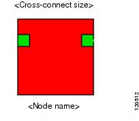
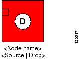
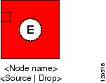
The following figure shows the color scheme used to represent the port state and alarm status in the Circuit Trace window. The color of the NEs and ports represents the highest alarm severity on that entity.
Figure 7-4 Colors of Port State and Alarm Status
Note
•
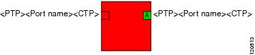
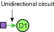
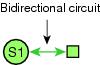
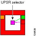
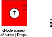
The following table describes the icons in the Circuit Trace window.
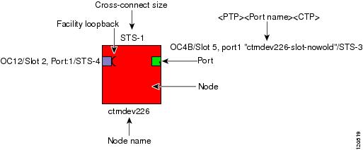
The following figure shows a sample circuit diagram that uses many of the objects and icons described in Table 7-20.
Figure 7-5 Sample Circuit Diagram
The Circuit Trace window provides tooltips. For each span, the tooltip displays link protection and bandwidth information. If a circuit passes through a VT tunnel, the intermediate nodes through which the VT tunnel passes are displayed and the level of cross-connection is STS-1.
For DRI circuits, DRI nodes are tagged with a DRI label.
The Circuit Trace also displays ONS 15600 circuits that are in Roll Pending state. The Roll From circuit path is marked in green and the Roll To circuit path is marked in orange. CTPs that are part of the roll are labeled RollTo and RollFrom.
7.2.21.1 Viewing a Port or Node from the Circuit Trace Window
Step 1
Step 2
Step 3
Step 4
7.2.21.2 Viewing a J1 Path Trace from the NE Explorer
The SONET J1 path trace is a repeated, fixed-length string comprised of 64 consecutive J1 bytes. You can use the string to monitor interruptions or changes to circuit traffic. The Cisco ONS 15454 Reference Manual available at http://www.cisco.com/univercd/cc/td/doc/product/ong/15400/index.htm shows the ONS 15454 cards that support path trace. DS-1 and DS-3 cards can transmit and receive the J1 field, while the EC-1, OC-3, OC-48AS, and OC-192 can only receive J1 bytes. Cards that are not listed in the reference manual do not support J1 bytes.
To view a J1 path trace from the NE Explorer:
Step 1
Step 2
Step 3
Step 4
Step 5
Table 7-21 Field Descriptions for the J1 Path Trace Dialog Box
STS Choices (J1 STS path trace only)
Choose the STS circuit that has path trace provisioned on the source and destination ports. This field does not appear on the J1 VC Path Trace dialog box.
VC3/VC4 Choices (J1 VC path trace only)
Choose the VC3 or VC4 circuit that has path trace provisioned on the source and destination ports. This field does not appear on the J1 STS Path Trace dialog box.
Path Trace Mode
Enable the path trace expected string by choosing one of the following values from the Path Trace Mode drop-down list:
•
•
•
Disable AIS and RDI if TIM-P is Detected
Check the Disable AIS on TIM-P check box if you want to suppress the Alarm Indication Signal (AIS) and the Remote Defect Indication (RDI) when the STS or VC3/VC4 path trace identifier mismatch (TIM-P) alarm is detected.
Path Trace String Size
Select the path trace string size.
Note
Current Expected String
Displays the current expected string. Click Hex Mode to display the string in hexadecimal mode. Click ASCII Mode to display the string in ASCII text.
New Expected String
If you set Path Trace Mode to Manual, enter the string that the OC-N port should receive in the New Expected String field.
Current Received String
Displays the current received string.
7.2.21.3 Editing a J1 Path Trace
Step 1
Step 2
Step 3
•
–
–
–
•
–
–
•
•
–
–
–
•
–
–
–
•
–
–
Step 4
•
•
•
7.2.21.4 Editing a J2 Path Trace
Step 1
Step 2
Step 3
•
–
–
–
•
–
–
•
•
–
–
–
•
–
–
–
•
–
–
Step 4
•
•
•
7.2.22 Modifying a Trace on CTC-Based NEs
Trace information can be used to find faults. The Modify Trace dialog box allows you to change the section trace information for applicable cards. Select a port and click Modify to open the Modify Trace dialog box. Fields shown depend on the type of card selected. The following table provides descriptions.
Note
7.2.23 Managing Circuit Notes on CTC-Based NEs
The Circuit Note dialog box allows you to view and add notes to circuits displayed in the Circuit table. If a circuit has a note, the Circuit Note tool appears under the Note column. Comments are visible to all users.
Step 1
Step 2
Step 3
7.2.24 Managing Circuit Rolls on CTC-Based NEs
Circuit rolls are managed from the Rolls table. The following table describes the various tasks that you can perform and the recommended order in which to complete these tasks.
Table 7-24 Rolls Table Management Tasks
View the Rolls table
—
Roll a circuit
Complete a roll
Force a valid signal
—
Finish a roll
Cancel a roll
Filter the Rolls table
Delete a roll
—
7.2.24.1 Viewing the Rolls Table
The Rolls table displays circuit roll information for the selected NE or NEs. The rolling maintenance function is available in CTC-based NEs to move live traffic from one entity to another. The connections can be single- or dual-ended. Only path-level (not line-level) bridging and rolling is supported.
To view the Rolls table, select a CTC-based NE in the Domain Explorer tree and choose Configuration > CTC-Based SONET NEs or CTC-Based SDH NEs > Rolls Table. The following table provides descriptions.
7.2.24.2 Rolling a Circuit
Use the Roll Circuit wizard to transfer CTC-based NE traffic from one facility to another without service interruption. The wizard is generally used to move a circuit off a card (for card or facility replacements) or to increase bandwidth utilization (for example, by moving lower-rate circuits across a shared high-rate circuit or rerouting circuits or parts of a circuit).
Step 1
Step 2
Step 3
•
–
–
•
Step 4
Step 5
Step 6
Step 7
a.
•
•
•
•
•
b.
Step 8
a.
b.
c.
d.
e.
•
•
•
•
Step 9
a.
b.
•
•
c.
d.
e.
f.
Step 10
a.
•
•
b.
c.
d.
e.
f.
Step 11
a.
b.
•
•
c.
Step 12
a.
b.
c.
•
•
•
•
Step 13
7.2.24.3 Completing a Roll
Use the Complete Roll button to terminate a manual roll. You can do this when a manual roll is in a ROLL_PENDING state and you have not yet completed the roll or have not canceled its sibling roll.
Step 1
Step 2
7.2.24.4 Forcing a Valid Signal
Use the Force Valid Signal button to force a valid signal on a pending roll so the roll will be completed.
Note
Step 1
Step 2
Step 3
7.2.24.5 Finishing a Roll
Use the Finish Roll tool to complete the circuit processing of both manual and automatic rolls. It changes the circuit state from ROLL_PENDING to ACTIVE.
Step 1
Step 2
7.2.24.6 Canceling a Roll
Use the Cancel Roll tool to cancel the selected roll. You can cancel a manual roll at any time; you can cancel an automatic roll only if the Roll Valid Signal is False.
Step 1
Step 2
Note
7.2.24.7 Filtering the Rolls Table
Use the Rolls table filter to filter circuit roll data according to criteria that you select and to display the results in the Rolls table.
Step 1
Step 2
Step 3
Step 4
7.2.24.8 Deleting a Roll
Step 1
Step 2
Note
Step 3
7.3 Managing BLSRs
The following table describes the various tasks that can be carried out from the BLSR table and the recommended order in which to complete these tasks.
Use the following procedures to manage BLSRs. You can launch the BLSR table from either the Domain Explorer or the NE Explorer.
7.3.1 Viewing the BLSR Table
You can launch the BLSR table from either the Domain Explorer (see Viewing the BLSR Table from the Domain Explorer) or the NE Explorer (see Viewing the BLSR Table from the NE Explorer). Use the BLSR table to view BLSRs that are available in a subnetwork. The BLSR table displays the BLSR attributes and the nodes that participate in the ring. You can select a BLSR in the table and edit, delete, exercise, or upgrade the ring from 2-fiber to 4-fiber. The following table provides descriptions.
7.3.1.1 Viewing the BLSR Table from the Domain Explorer
In the Domain Explorer, select the NE; then, choose Configuration > CTC-Based SONET NEs > BLSR Table. The BLSR table opens.
Figure 7-6 BLSR Table
7.3.1.2 Viewing the BLSR Table from the NE Explorer
Step 1
Step 2
•
•
•
•
•
•
•
•
•
•
•
•
•
7.3.2 Creating a BLSR for an Individual Node
Use the BLSR Creation wizard to create BLSRs for the selected CTC-based SONET NE. The creation wizard can be launched by selecting an NE from the Domain Explorer, Subnetwork Explorer, or Network Map.
Note
7.3.2.1 Creating a BLSR from the Domain Explorer
Step 1
Step 2
Step 3
•
•
•
•
•
Step 4
7.3.2.2 Creating a BLSR from the NE Explorer
Step 1
Step 2
Step 3
Step 4
•
•
•
•
•
•
•
For 4-fiber BLSRs, complete the following information:
•
•
•
Step 5
Note
Step 6
Step 7
Note
Step 8
Step 9
Step 10
a.
b.
c.
d.
e.
f.
g.
7.3.3 Creating BLSRs for Multiple Nodes Simultaneously
Use the Create BLSR wizard from the Domain Explorer to create a BLSR for all desired SONET nodes simultaneously.
7.3.4 Viewing the BLSR Ring Map Table
The Ring Map table contains BLSR information for the selected object in the table.
Step 1
Step 2
7.3.5 Viewing the BLSR Squelch Table
When multiple fiber cuts isolate a BLSR node, the Squelch table displays the circuits that are isolated on the node by STS number, east source/destination, and west source/destination. The table is read-only.
Step 1
Step 2
Step 3
7.3.6 Editing a BLSR
Step 1
Step 2
Step 3
•
•
•
Step 4
7.3.7 Exercising a BLSR
The BLSR Exercise Schedule dialog box displays a graphical representation of a BLSR, including the following details:
•
•
•
•
•
•
Step 1
Step 2
Step 3
Step 4
7.3.8 Changing the BLSR Exercise Interval
The interval between BLSR exercises can be configured in the Control Panel. This interval represents the interval between east and west tasks of a ring exercise task.
Step 1
Step 2
Step 3
Step 4
7.3.9 Using the BLSR Upgrade Table
Use the BLSR Upgrade table to upgrade a 2-fiber BLSR to a 4-fiber ring. The BLSR Upgrade wizard allows you to select the span reversion along with upgrade options. After selecting the spans, the protect ports selection wizard is displayed.
The following table describes the fields in the BLSR Upgrade table.
7.3.10 Upgrading a BLSR
Use the Upgrade BLSR wizard to upgrade 2-fiber BLSRs to 4-fiber BLSRs. Only OC-48 (or higher) rings can be upgraded.
Step 1
Step 2
Step 3
•
•
Step 4
Step 5
•
•
•
•
•
Step 6
7.3.11 Filtering the BLSR Table
Step 1
Step 2
Step 3
7.3.12 Deleting a BLSR
You can delete a BLSR from the Domain Explorer or the NE Explorer.
7.3.12.1 Deleting a BLSR from the Domain Explorer
Step 1
Step 2
Step 3
7.3.12.2 Deleting a BLSR from the NE Explorer
Step 1
Step 2
Step 3
Step 4
7.4 Managing MS-SPRings
The following table describes the various tasks that can be carried out from the MS-SPRing table.
Table 7-37 MS-SPRing Management Tasks
View the MS-SPRing table
Use the MS-SPRing table to view MS-SPRings that are available in a subnetwork. The MS-SPRing table displays the MS-SPRing attributes and the nodes that participate in the ring.
View the MS-SPRing table from the Domain Explorer or NE Explorer.
—
Create an MS-SPRing
Use the MS-SPRing Creation wizard to create MS-SPRings for the selected ONS 15454 SDH or ONS 15600 SDH NE.
In the MS-SPRing table, choose Edit > Create MS-SPRing.
—
Creating an MS-SPRing for an Individual Node
Edit an MS-SPRing
Use the Edit MS-SPRing window to modify the MS-SPRing.
In the MS-SPRing table, choose Edit > Edit MS-SPRing.
Upgrade a 2-fiber MS-SPRing to a 4-fiber ring
Use the MS-SPRing Upgrade table to upgrade a 2-fiber MS-SPRing to a 4-fiber ring.
In the MS-SPRing table, choose Edit > Edit MS-SPRing.
—
Upgrade an MS-SPRing
Allows you to upgrade the selected MS-SPRing.
In the MS-SPRing table, choose Edit > Upgrade MS-SPRing.
View the Ring Map table
The Ring Map table contains the MS-SPRing information for the selected object in the table.
—
—
View the MS-SPRing Squelch table
The MS-SPRing Squelch table displays the circuits that are isolated on the node by STS number, east source/destination, and west source/destination.
—
—
Exercise an MS-SPRing
The Exercise MS-SPRing window allows you to set up MS-SPRing scheduling data to occur immediately, or at an exact time.
In the MS-SPRing table, choose Edit > Exercise MS-SPRing.
Change the MS-SPRing exercise interval
The interval between the MS-SPRing exercise can be configured in the Control Panel.
—
—
Filter the MS-SPRing table
Allows you to select the way BLSRs are displayed in the BLSR table.
In the MS-SPRing table, choose File > Filter.
Delete an MS-SPRing
Deletes the selected MS-SPRing.
In the MS-SPRing table, choose Edit > Delete MS-SPRing.
7.4.1 Viewing the MS-SPRing Table
Use the MS-SPRing table to view MS-SPRings that are available in a subnetwork. The MS-SPRing table displays the MS-SPRing attributes and the nodes that participate in the ring. You can select an MS-SPRing in the table and edit, delete, exercise, or upgrade the ring from 2-fiber to 4-fiber.
The following table provides descriptions.
You can launch the MS-SPRing table from either the Domain Explorer or the NE Explorer.
7.4.1.1 Viewing an MS-SPRing from the Domain Explorer
In the Domain Explorer, click an ONS 15454 SDH or ONS 15600 SDH NE; then, choose Configuration > CTC-Based SDH NEs > MS-SPRing Table. The MS-SPRing table displays the information shown in Table 7-38.
7.4.1.2 Viewing an MS-SPRing from the NE Explorer
Step 1
Step 2
•
•
•
•
•
•
•
•
•
•
•
•
7.4.2 Creating an MS-SPRing for an Individual Node
Use the MS-SPRing Creation wizard to create MS-SPRings for the selected ONS 15454 SDH or ONS 15600 SDH NE. MS-SPRings share the ring bandwidth equally between working and protection traffic. Half of the payload bandwidth is reserved for protection in each direction, making the communication pipe half-full under normal operation.
Note
You can create an MS-SPRing from the Domain Explorer or the NE Explorer.
7.4.2.1 Creating an MS-SPRing from the Domain Explorer
Step 1
Step 2
Step 3
•
•
•
•
•
Step 4
7.4.2.2 Creating an MS-SPRing from the NE Explorer
Step 1
Step 2
Step 3
•
•
•
•
•
•
•
•
•
Step 4
7.4.3 Creating MS-SPRings for Multiple Nodes Simultaneously
Use the Create MS-SPRing wizard to create an MS-SPRing for all desired SDH nodes simultaneously.
7.4.4 Editing an MS-SPRing
Use the MS-SPRing Edit window to modify the ring ID, ring reversion, and span reversion on a ring.
Step 1
Step 2
Step 3
•
•
•
Step 4
7.4.5 Using the MS-SPRing Upgrade Table
Use the MS-SPRing Upgrade table to upgrade a 2-fiber MS-SPRing to a 4-fiber ring. The MS-SPRing Upgrade wizard allows you to select the span reversion along with upgrade options. After selecting the spans, the protect ports selection wizard is displayed.
The following table provides descriptions.
7.4.6 Upgrading an MS-SPRing
Only STM16 (or higher) rings can be upgraded.
Step 1
Step 2
Step 3
•
•
–
–
–
Step 4
•
•
•
•
•
Step 5
7.4.7 Viewing the MS-SPRing Ring Map Table
The Ring Map table contains MS-SPRing information for the selected object in the table.
Step 1
Step 2
Step 3
7.4.8 Viewing the MS-SPRing Squelch Table
When multiple fiber cuts isolate an MS-SPRing node, the Squelch table displays the circuits that are isolated on the node by STS number, east source/destination, and west source/destination. The table is read-only.
Step 1
Step 2
Step 3
7.4.9 Exercising an MS-SPRing
The MS-SPRing Exercise Schedule dialog box displays a graphical representation of an MS-SPRing, including the following details:
•
•
•
•
•
•
Step 1
Step 2
Step 3
The job is queued in the Job Monitor table. For more information, see 4.6.6 Monitoring Scheduled Tasks, page 4-97.
7.4.10 Changing the MS-SPRing Exercise Interval
The interval between the MS-SPRing exercise can be configured in the Control Panel. This interval represents the interval between east and west tasks of a ring exercise task.
Step 1
Step 2
Step 3
Step 4
7.4.11 Filtering the MS-SPRing Table
Step 1
Step 2
Step 3
7.4.12 Deleting an MS-SPRing
You can delete an MS-SPRing from the Domain Explorer or the NE Explorer.
7.4.12.1 Deleting an MS-SPRing from the Domain Explorer
Step 1
Step 2
Step 3
7.4.12.2 Deleting an MS-SPRing from the NE Explorer
Step 1
Step 2
Step 3
Step 4
7.5 Managing VLANs for E-Series Cards
VLANs are managed at the network partition level. All VLANs that are discovered on one NE are propagated to all available NEs under the same network partition. Creating, editing, or deleting VLANs affects all the NEs under the network partition.
Caution
If you use CTC to manage VLANs, CTM will discover two VLANs with the same name but different IDs if the following conditions exist:
•
•
•
A similar situation arises when two or more VLANs are created with the same ID but different names.
Note
The following table describes the various tasks that can be performed from the Manage VLANs dialog box.
7.5.1 Creating a VLAN
Use the Manage VLANs dialog box to create new VLANs or delete existing VLANs from the CTM domain. All CTM user types can access the Manage VLANs dialog box, but Operators cannot create or delete VLANs.
The Manage VLANs dialog box displays a list of all available VLANs in the CTM domain. The list is ordered alphanumerically by VLAN name, where numbers precede letters and uppercase letters precede lowercase ones.
Step 1
Alternatively, perform one of the following tasks to open the Manage VLANs dialog box:
•
•
Step 2
Step 3
Step 4
Step 5
Note
7.5.2 Tracing a VLAN
The VLAN Trace table displays a tabular representation of the endpoints associated with the VLAN in the selected network partition.
Step 1
Step 2
7.5.3 Deleting a VLAN
Step 1
Step 2
Note
Step 3
Step 4
7.6 Managing VLANs (ML-Series Cards)
A VLAN is an end-to-end service within a Layer 2 topology. When provisioning a VLAN, CTM internally configures bridge groups, one on each card, wherever an Ethernet service drop is specified. A bridge group associates a service drop with the service VLAN ID, the optical virtual port subinterface. A VLAN service is a collection of bridge groups on a particular Layer 2 topology.
Bridge groups are invisible on the Layer 2 service provisioning application. You can review the associated service drops on each VLAN service.
Step 1
Step 2
Step 3
Step 4
Step 5
Step 6
7.7 Provisioning Data Services
Note
Note
Metro Ethernet service capability is available through the ML-series cards on the ONS 15454 NE and the ML-100T-8 card on the ONS 15310 CL and ONS 15310 MA.
These cards provide the Ethernet interface (access point) to the service provider customer equipment and enable the transport of the customer traffic over the optical network domain.
CTM supports Layer 2, Ethernet, service provisioning, and discovery. Before an Ethernet service can be provisioned, you must define an access domain, referred to in CTM as a Layer 2 topology. A Layer 2 topology consists of optical circuits with specific Layer 2 configurations. CTM supports Layer 2 topology provisioning and discovery. The following table summarizes the types of Layer 2 topology supported.
The Ethernet service types supported by CTM are summarized in the following table.
Caution
7.7.1 Layer 2 Topology Table Management Tasks
The following table describes the various tasks that can be carried out from the Layer 2 Topology table and the recommended order in which to complete these tasks.
Table 7-51 Layer 2 Topology Table Management Tasks
Initialize Layer 2 cards. Initialize each card with the barebone configuration file through the CTM NE Explorer. The barebone configuration file is the minimum configuration required for CTM to support the Layer 2 topology and Layer 2 services on it.
—
—
Back up/restore ML configuration files on the ML-series cards.
—
—
Backing Up and Restoring ML Configuration Files on Layer 2 Cards
Provision a Layer 2 topology.
—
—
View the Layer 2 Topology table, which displays all the configured Layer 2 topologies.
Configuration > CTC-Based SONET NEs or CTC-Based SDH NEs > L2 Topology Table
—
Use the Create Layer 2 Topology wizard to create a Layer 2 topology (point-to-point topology or an RPR).
In the Layer 2 Topology table, choose Configuration > Create L2 Topology
Delete a Layer 2 topology.
In the Layer 2 Topology table, choose Configuration > Delete L2 Topology
Enable a Layer 2 service.
In the Layer 2 Topology table, choose Configuration > Enable L2 Service
—
Use the Modify L2 Topology wizard to modify a Layer 2 topology.
In the Layer 2 Topology table, choose Configuration > Modify L2 Topology
Use the Filter dialog box to filter the L2 Topology table.
In the Layer 2 Topology table, choose File > Filter
Modify a Layer 2 port. Use the Modify Ports dialog box to modify Layer 2 topology endpoints.
In the Layer 2 Topology table, choose Configuration > Modify Ports
—
Insert or remove cards in an existing RPR topology.
Configuration > Add/Remove Card(s)
—
Configure Layer 2 services.
—
—
7.7.2 Initializing Layer 2 Cards
Before provisioning, you must first enable CTM communication with the Layer 2 cards. The cards to be managed should be initialized with a minimum configuration.
To allow CTM to communicate with Layer 2 cards, you must configure each card with a username, password, and hostname. You can customize this information in the Cisco IOS configuration file before loading it on the ML-series card.
When a Layer 2 topology is configured on NEs, CTM configures each ML-series card with a barebone configuration file. The barebone configuration file is the minimum configuration required for CTM to support the Layer 2 topology and Layer 2 services on it.
CTM provides the following barebone configuration files:
•
•
•
Note
A sample Cisco IOS configuration file is shown below.
Note
!
version 12.1
no service pad
service timestamps debug datetime msec localtime
service timestamps log datetime msec localtime
service password-encryption
service internal
!
hostname default46
!
logging buffered 4096 debugging
!
username CISCO15 privilege 15 password 7 112A2D2846405847
ip subnet-zero
!
!
ip classless
no ip http server
!
!
logging history size 100
snmp-server enable traps snmp authentication warmstart linkdown linkup coldstart
snmp-server enable traps bridge
snmp-server enable traps flash insertion removal
snmp-server enable traps hsrp
snmp-server enable traps config
snmp-server enable traps entity
snmp-server enable traps bgp
snmp-server enable traps syslog
!
!
line con 0
exec-timeout 0 0
line vty 0 4
exec-timeout 0 0
login local
!
end
You must perform the following steps before CTM can manage Layer 2 cards correctly:
Step 1
Step 2
7.7.3 Backing Up and Restoring ML Configuration Files on Layer 2 Cards
You can back up and restore ML configuration files using CTC or the Cisco IOS commands on the ML-series cards.
•
•
7.7.4 Naming Convention for Discovered Layer 2 Topologies
CTM follows a set naming convention when creating Layer 2 topologies.
If an RPR topology is created through CTM with the name toponame, the Layer 1 member circuits are named as follows: toponame.1CTML2, toponame.2CTML2, and so on.
During discovery, if Layer 1 circuits matching this naming convention are discovered, a Layer 2 topology with the name toponame is added to CTM.
If the CTM naming convention is not followed for discovered circuits, the RPR topology takes the name of one of the circuits in the RPR topology.
In the case of point-to-point topologies, the Layer 1 circuit has the same name as the topology. On the other hand, when a Layer 1 circuit between an ML and a non-ML series card is discovered, a point-to-point topology with the same name as the L1 circuit is added to the CTM database.
Note
For RPR or point-to-point topologies created by creating Layer 1 circuits for a TL1 interface, the name appears as a numeric string. This numeric string is based on the unique number used to identify the circuits.
7.7.5 Provisioning the Layer 2 Topology
CTM allows you to create VCAT circuits and their constituent member circuits during Layer 2 topology creation. To support a Layer 2 topology, for RPR, CTM allows you to create all VCAT circuits (and contained member circuits), all CCAT circuits, or a combination of VCAT and CCAT circuits. For a point-to-point L2 topology you can create either a VCAT or a CCAT circuit.
The Layer 2 topology can be a point-to-point optical circuit, or RPR consisting of a chain of optical circuits, or hub and spoke consisting of multiple optical circuits connected in a hub and spoke fashion:
•
Table 7-52 NE Models and Cards Supported by CTM for L2 Topology
L2-supported source NE?
No
Yes
Yes
No
Yes
Yes
No
No
No
Yes
Yes
Yes
Yes
Yes
No
No
—
Yes
Yes
No
Yes
Yes
—
—
—
Yes
Yes
No
Yes
Yes
—
—
—
Yes
Yes
No
Yes
Yes
—
—
—
Yes
Yes
No
Yes
Yes
—
—
—
Yes
Yes
No
Yes
Yes
—
—
—
—
—
Yes1
No
No
—
—
1 Available only in LAN extension (LEX) encapsulation mode.
Note
Note
•
•
–
–
–
When deployed as hub and spoke, the ML-series cards can be placed at the spoke locations, with the G-series cards providing an extension of the traffic to a Cisco 7600, which forms the hub of the architecture. This arrangement provides a cost-effective way to interface to the Cisco 7600. Alternatively, the ML-series cards can be deployed at both the hub and the spoke sites. See the ML-series Metro Ethernet Design and Implementation Guide for network configurations.
Note
When deployed as RPR, all sites contain ML-series cards.
The Create Circuit wizard is used to repair a Layer 2 topology, when the bottom circuit has been deleted or removed erroneously.
The Layer 2 Topology table reports the operational state and the state for each Layer 2 topology. For point-to-point topologies, the operational state reflects the state of the underlying optical circuit. For RPR topologies, the operational state can have one of the following values:
•
•
•
The Layer 2 Service Resync state provides the configuration synchronization state after discovery of the Layer 2 topology. The state can be In-Progress, Complete, Partially Complete, Layer 2 Service Not Ready, or Sync Failed. VLAN status is different and is available in the Layer 2 Services table.
CTM can discover a Layer 2 topology through the Create Layer 2 Topology wizard or Create Circuit wizard, through CTC, or through the TL1 interface.
A Layer 2 topology provisioned by this application is Layer 2 service enabled, meaning the optical circuit and the Cisco IOS configuration are set for subsequent Layer 2 services. However, a Layer 2 topology created through other means (such as through the Create Circuit wizard, CTC, or TL1 interface) is not Layer 2 service enabled. This is because the Cisco IOS configuration is missing. This type of Layer 2 topology must be Layer 2 service enabled if you want to provision Layer 2 services.
Note
Note
Note
7.7.6 Viewing the L2 Topology Table
In the Domain Explorer window, choose Configuration > CTC-Based SONET NEs or CTC-Based SDH NEs > L2 Topology Table. The Layer 2 Topology table opens.
Figure 7-7 Layer 2 Topology Table
The Layer 2 Topology table displays all the configured Layer 2 topologies. It also reports the bandwidth settings for each Layer 2 topology. These are set for each Layer 2 topology and added through the Layer 2 topology wizard. The following bandwidth settings are reported:
•
•
•
•
•
The following table describes the fields in the L2 Topology table.
7.7.7 Creating a Layer 2 Topology
Use the Create Layer 2 Topology wizard to set up a point-to-point or RPR topology.
Note
7.7.7.1 Creating a Point-to-Point Layer 2 Topology
Note
Step 1
Step 2
Tip
Figure 7-8 Create Layer 2 Topology Wizard
The following table describes the fields in the wizard.
Note
Step 3
•
•
•
•
•
Note
•
•
•
–
–
–
–
–
•
Note
–
–
–
Step 4
Step 5
a.
•
•
•
•
•
•
•
b.
•
•
•
•
•
•
Step 6
Group 2 panes as required.Step 7
•
•
•
•
•
•
•
•
Step 8
a.
•
•
b.
•
•
c.
d.
Note
e.
•
•
•
f.
•
•
•
•
Step 9
a.
•
•
•
•
•
b.
c.
d.
•
•
e.
f.
g.
h.
Note
i.
Step 10
a.
•
•
•
•
•
•
•
b.
c.
d.
Step 11
•
•
•
Step 12
•
•
Step 13
a.
b.
c.
d.
e.
f.
g.
h.
Step 14
a.
b.
c.
d.
e.
f.
g.
h.
i.
Step 15
a.
b.
c.
•
•
•
•
Note
Step 16
Note
Caution
7.7.7.2 Creating an RPR Layer 2 Topology
Step 1
Step 2
Tip
Note
Step 3
•
•
•
•
Step 4
Step 5
a.
b.
c.
Step 6
Step 7
Step 8
Step 9
Step 10
•
•
•
•
•
•
•
•
Step 11
Step 12
a.
b.
Note
c.
d.
e.
Step 13
Step 14
•
–
–
–
•
Step 15
a.
b.
c.
•
•
•
d.
e.
•
•
•
•
f.
g.
Step 16
a.
•
•
•
b.
c.
•
•
•
•
•
d.
•
•
•
e.
f.
g.
h.
i.
Step 17
Note
7.7.8 Deleting a Layer 2 Topology
You cannot delete a Layer 2 topology if there are VLANs associated with it. Make sure to delete all VLANs associated with the Layer 2 topology before deleting the Layer 2 topology. See Tracing a VLAN.
Step 1
Step 2
Step 3
7.7.9 Enabling a Layer 2 Service
To ensure that provisioning is available for Layer 2 services, the Layer 2 topology attributes must be configured correctly on the underlying optical circuits. A Layer 2 topology can be configured using the TL1 interface, CTC, or CTM. Layer 2 topologies configured using CTM are Layer 2 service-ready. Layer 2 topologies configured using the TL1 interface, CTC, or CTM Create Circuit wizard are not Layer 2 service-ready. Some examples of the latter case are:
•
•
•
Caution
Step 1
Step 2
Step 3
Note
7.7.10 Modifying a Layer 2 Topology
Note
Use the Modify L2 Topology window to modify the parameters of the selected Layer 2 topology. The window has two tabs, General and Bandwidth.
Step 1
Step 2
Step 3
Step 4
Step 5
Note
Step 6
Step 7
7.7.11 Filtering the Layer 2 Topology Table
Step 1
Step 2
Step 3
Step 4
7.7.12 Modifying Ports in a Layer 2 Topology
Use the Modify Ports dialog box to modify Layer 2 topology endpoints.
Step 1
Step 2
Step 3
Step 4
7.7.13 Inserting or Deleting a Card on an RPR Topology
This section describes how to insert or delete cards on an existing RPR topology.
Note
7.7.13.1 Inserting a Card into an Existing RPR Topology
Note
Note
interface SPR1
no ip address
no keepalive
spr station-id 1
hold-queue 150 in
!
Step 1
Step 2
Step 3
Step 4
Step 5
Tip
Step 6
Step 7
Step 8
Step 9
Step 10
The Insert Circuit Segment Info pane opens, displaying the circuits on the L2 topology that will exist after inserting or deleting the card. Circuits with a white background must be created to complete the insert or delete operation.
Step 11
Step 12
•
–
–
–
•
Step 13
a.
b.
c.
•
•
•
d.
e.
•
•
•
•
f.
g.
Step 14
a.
•
•
•
b.
c.
•
•
•
•
•
d.
•
•
•
e.
f.
g.
h.
i.
Step 15
Step 16
7.7.13.2 Removing a Card from an Existing RPR Topology
To remove an ML card from a topology, at least two other ML cards must be part of the topology, because a valid topology has endpoints on at least two different NEs. For example, if you have two ML cards on a single NE, an L2 topology cannot be created across the two ML cards. If you have a topology with three ML cards (two cards on one NE and a third card on another NE), removal of the third card from the topology is not a valid operation because it reduces the number of NEs from two to one.
Note
Step 1
Step 2
Step 3
Step 4
Step 5
Tip
Step 6
Step 7
Step 8
Step 9
Step 10
Step 11
Step 12
Step 13
•
–
–
–
•
Step 14
a.
b.
c.
•
•
•
d.
e.
•
•
•
•
f.
g.
Step 15
a.
•
•
•
b.
c.
•
•
•
•
•
d.
•
•
•
e.
f.
g.
h.
i.
Step 16
7.7.14 Layer 2 Service Management Tasks
VLAN service is a collection of bridge groups within a Layer 2 topology. It can span multiple ML-series cards on a particular Layer 2 topology. In a point-to-point topology, no Layer 2 configuration is done on E-series, G-series, ML-100T-8, CE-100T-8, or OC-N cards. In an RPR topology, a VLAN can span the entire ring.
You can configure a VLAN service that consists of multiple service drops (Ethernet drops). Each service drop is classified according to:
•
•
In a VLAN service, the recommended mix of port type and connection type is as follows:
•
•
The following table summarizes the service drop configurations and associated parameters.
The following table describes the Layer 2 service tasks supported in CTM and the recommended order in which to complete these tasks. This table also describes how to open the appropriate windows to accomplish these tasks.
7.7.14.1 Creating a Layer 2 Service
Use the Create L2 Service wizard to create a new Layer 2 service.
Note
Step 1
Step 2
Step 3
Table 7-62 Field Descriptions for the Create L2 Service Wizard
Layer 2 Topology Name
The name of the topology on which the Layer 2 service is created.
Service Provider VLAN ID
A unique number in a topology that is used to represent the VLAN. The valid range for service provider VLAN IDs is 1 to 4096. By default, the first VLAN number is displayed as 2, because VLAN number 1 is an administration VLAN. You can change the default value and create VLAN 1, if it is available.
Customer ID
The unique identification number of the customer for whom the Layer 2 service is being created.
Service ID
The service identification number of the customer for whom the Layer 2 service is being created.
—
Summarizes the selections you made in the wizard panes. To change the L2 service summary, click Back and change your selection(s).
Selected Drops (Node/Slot/Port)
The drop ports selected in the L2 Service Drop Ports table.
NE ID
Select the user-defined name of the selected NE.
Slot
The ML-series card slot number.
Type
The ML-series card type.
Port
The port number on the ML-series card.
Port Type
The available port type—UNI, NNI, or Any. If both UNI and NNI port types are available, Any is displayed.
Connection Type
The connection type—QinQ, dot1q, Untagged, or Any. For the UNI port type, connection types are QinQ, dot1q, and Untagged. For the NNI port type, only the dot1q connection type is allowed. If all types are available, this field is shown as Any.
NE ID
The user-defined name of the selected NE.
Slot
The ML-series card slot number.
Type
Displays the ML-series card type—ML100 or ML1000.
Add/Remove
Click Add to add the selected drop from the Available Layer 2 Service Drops list to the Selected L2 Service Drops list. Click Remove to remove drops from the Selected L2 Service Drops list.
Apply QoS parameters to all UNI ports
When selected, the quality of service (QoS) parameters specified in the QoS Parameters screen are applied to all the drops.
RSTP Enable
When checked, RSTP protocol for the VLAN is enabled.
NE ID
The user-defined name of the selected NE.
Port
The port number on the ML-series card.
Enable
Used to enable or disable the drop port. When checked, the drop port is enabled.
Port Type
The port type—UNI or NNI.
Connection Type
The connection type. For the UNI port type, the connection type is QinQ, dot1q, or Untagged. For the NNI port type, only the NNI connection type is permitted.
Port VLAN ID
The port VLAN ID used for dot1q drops. By default, the NNI dot1q drop is populated with the SP VLAN ID.
Cos Accounting
When checked the collection of CoS PM on a VLAN service drop is enabled.
RSTP
When checked, RSTP is enabled. This checkbox is enabled only when you configure a dot1q drop of the VLAN.
Match Any
Matches all the traffic. When selected, all other fields (DSCP, IP Precedence, and CoS) are disabled.
Match DSCP
Matches the DSCP value. The valid range is from 0 to 63.
DSCP Value
Displays the DSCP value.
Match IP
Matches the IP value. The valid range is from 0 to 7.
IP Value
Displays the IP value.
Match CoS
Matches the CoS value. The valid range is from 0 to 7.
CoS Value
Displays the CoS value.
AND/OR
Selecting AND indicates Match All and Match Any of the traffic classifications, respectively.
The QoS profiles that are created with AND criteria are applied only to dot1Q (subinterface). For AND criteria only, a single value is allowed on CoS, DSCP, and IP Precedence.
Note
Committed Rate
Displays the committed traffic rate value.
Committed Burst Size
Displays the committed burst size.
CIR CoS Type
Committed traffic CoS type (Trust or CoS Marked).
CIR CoS Value
Committed traffic CoS value. The valid range is from 0 to 7.
Excess Action
Excess traffic action type (Discard or Allow).
Peak Rate
Displays the peak traffic rate value.
Peak Burst Size
Displays the peak traffic burst value.
PIR CoS Type
Displays the peak traffic CoS type (Trust or CoS Marked).
PIR CoS Value
Displays the peak traffic CoS value. The valid range is from 0 to 7.
Violate Action
Displays the violate traffic action type (Discard or Allow).
Violate CoS
Displays the violate traffic CoS type (Trust or CoS Marked).
Violate CoS Value
Displays the violate traffic CoS value. The valid range is from 0 to 7.
Best Effort Type
Displays the best effort traffic type (Line-Rate or Rate-Limited).
Max Rate
Displays the maximum rate value.
Max Burst Size
Displays the maximum burst value.
NE ID
Select a user-defined NE name from the drop-down lists.
Slot
Select the ML card slot number from the drop-down lists.
Type
Displays the ML-series card type—ML100 or ML1000.
Port
Select the port number on the ML card.
MTU
Enter an MTU size. The valid range is from 64 to 9000. The default value is 1500.
Speed
Select the speed from the drop-down list. The Speed drop-down list displays three values: 10, 100, and auto. For an ML1000 card, auto is the only supported option.
Duplex
Select the Duplex value from the drop-down list. The Duplex drop-down list displays three values: full, half, and auto, based upon the type of card selected. For example, for an ML1000 card, auto is the only supported option.
Flow Control (send)
Select the Flow Control (send) value from the drop-down list. The Flow Control (send) drop-down box displays three values: off, on, and desired. These values are supported by both the Fast Ethernet and Gigabit Ethernet ports.
Flow Control (receive)
Select the Flow Control (receive) value from the drop-down list. The Flow Control (receive) drop-down box displays three values: off, on, and desired. These values are supported by the Gigabit Ethernet ports only.
Load from QoS Profile
Select the QoS profile from the list displayed. See Creating a QoS Profile for details on how to create a QoS profile.
Note
Match Any
Matches all the traffic. When selected, all other fields (DSCP, IP Precedence, and CoS) are disabled.
Match DSCP
Matches the DSCP value. The valid range is from 0 to 63.
DSCP Value
Displays the DSCP value.
Match IP
Matches the IP value. The valid range is from 0 to 7.
IP Value
Displays the IP value.
Match CoS
Matches the CoS value. The valid range is from 0 to 7.
CoS Value
Displays the CoS value.
AND/OR
Selecting AND indicates Match All and Match Any of the traffic classifications, respectively.
The QoS profiles that are created with AND criteria are applied only to dot1Q (subinterface). For AND criteria only, a single value is allowed on CoS, DSCP, and IP Precedence.
CIR Type
Displays the CIR type.
Committed Rate
Displays the committed traffic rate value.
Committed Burst Size
Displays the committed burst size.
CIR CoS Type
Committed traffic CoS type (Trust or CoS Marked).
CIR CoS Value
Committed traffic CoS value. The valid range is from 0 to 7.
Excess Action
Excess traffic action type (Discard or Allow).
Peak Rate
Displays the peak traffic rate value.
Peak Burst Size
Displays the peak traffic burst value.
PIR CoS Type
Displays the peak traffic CoS type (Trust or CoS Marked).
PIR CoS Value
Displays the peak traffic CoS value. The valid range is from 0 to 7.
Violate Action
Displays the violate traffic action type (Discard or Allow).
Violate CoS
Displays the violate traffic CoS type (Trust or CoS Marked).
Violate CoS Value
Displays the violate traffic CoS value. The valid range is from 0 to 7.
Best Effort Type
Displays the best effort traffic type (Line-Rate or Rate-Limited).
Max Rate
Displays the maximum rate value.
Max Burst Size
Displays the maximum burst value.
Load from QoS Profile
Select the QoS profile from the list displayed. See Creating a QoS Profile for details on how to create a QoS profile.
Note
Match Any
Matches all the traffic. When selected, all other fields (DSCP, IP Precedence, and CoS) are disabled.
Match DSCP
Matches the DSCP value. The valid range is from 0 to 63.
Match IP Precedence
Matches the IP Precedence value. The valid range is from 0 to 7.
Match CoS
Matches the CoS value. The valid range is from 0 to 7.
AND
Selecting AND indicates Match All and Match Any of the traffic classifications, respectively.
The QoS profiles that are created with AND criteria are applied only to dot1Q (subinterface). For AND criteria only, a single value is allowed on CoS, DSCP, and IP Precedence.
Line Rate
Rate and burst of the Ethernet port are applicable.
Rate Limited
User-specified rate and burst limits are applicable.
Committed Rate
Displays the committed rate.
Committed Burst Size
Displays the committed burst size.
Trust
CoS transmit value set to 0.
Mark CoS
The Layer 2 Mark CoS value entered. The valid range is from 0 to 7.
Discard
Excess traffic action should be set to "drop."
Allow
Excess traffic with CoS, as marked by the user, is transmitted.
Peak Rate
Peak rate value.
Peak Burst
Peak burst value.
Trust
CoS transmit value set to 0.
Mark CoS
The Layer 2 Mark CoS value entered. The valid range is from 0 to 7.
Discard
Excess traffic action should be set to "drop."
Allow
Excess traffic with CoS, as marked by the user, is transmitted.
Trust
CoS transmit value set to 0.
Mark CoS
The Layer 2 Mark CoS value entered. The valid range is from 0 to 7.
Line Rate
Rate and burst of the Ethernet port are applicable.
Rate Limited
User-specified rate and burst limits are applicable.
Max Rate
The maximum rate value.
Max Burst
The maximum burst value.
Trust
CoS transmit value set to 0.
Mark CoS
The Layer 2 Mark CoS value entered. The valid range is from 0 to 7.
Apply QoS parameters to all UNI ports
When selected, the QoS parameters specified in the QoS Parameters screen are applied to all the drops.
RSTP Enable
When checked, RSTP is enabled.
NE ID
The user-defined name of the selected NE.
Slot
Information about the slot.
Type
Displays the ML-series card type—ML100 or ML1000.
Port
The port number on the ML card.
Enable
Used to enable or disable the drop port. When checked, the drop port is enabled.
Port Type
The port type—UNI or NNI.
Connection Type
The connection type. For the UNI port type, the connection type is QinQ, dot1q, or Untagged. For the NNI port type, only the NNI connection type is permitted.
Port VLAN ID
The port VLAN ID used for dot1q drops. By default, the NNI dot1q drop is populated with the service provider VLAN ID.
CoS Accounting
When checked the collection of CoS PM on a VLAN service drop is enabled.
RSTP
When checked, RSTP is enabled. This is enabled only when the you configure a dot1q drop of the VLAN.
PM State
Check this check box to collect PM data for each drop port in an ML-series card. Checking the PM State box sets the Cisco IOS cos accounting command in each appropriate front port.
Match Any
Matches all the traffic. When selected, all other fields (DSCP, IP Precedence, and CoS) are disabled.
Match DSCP
Matches the DSCP value. The valid range is from 0 to 63.
DSCP Value
Displays the DSCP value.
Match IP
Matches the IP value. The valid range is from 0 to 7.
IP Value
Displays the IP value.
Match CoS
Matches the CoS value. The valid range is from 0 to 7.
CoS Value
Displays the CoS value.
AND/OR
Selecting AND indicates Match All and Match Any of the traffic classifications, respectively.
The QoS profiles that are created with AND criteria are applied only to dot1Q (subinterface). For AND criteria only, a single value is allowed on CoS, DSCP, and IP Precedence.
Note
Committed Rate
Displays the committed traffic rate value.
Committed Burst Size
Displays the committed burst size.
CIR CoS Type
Committed traffic CoS type (Trust or CoS Marked).
CIR CoS Value
Committed traffic CoS value. The valid range is from 0 to 7.
Excess Action
Excess traffic action type (Discard or Allow).
Peak Rate
Displays the peak traffic rate value.
Peak Burst Size
Displays the peak traffic burst value.
PIR CoS Type
Displays the peak traffic CoS type (Trust or CoS Marked).
PIR CoS Value
Displays the peak traffic CoS value. The valid range is from 0 to 7.
Violate Action
Displays the violate traffic action type (Discard or Allow).
Violate CoS
Displays the violate traffic CoS type (Trust or CoS Marked).
Violate CoS Value
Displays the violate traffic CoS value. The valid range is from 0 to 7.
Best Effort Type
Displays the best effort traffic type (Line-Rate or Rate-Limited).
Max Rate
Displays the maximum rate value.
Max Burst Size
Displays the maximum burst value.
NE ID
Select a user-defined NE name from the drop-down lists.
Slot
Select the ML card slot number from the drop-down lists.
Type
Displays the ML-series card type—ML100 or ML1000.
Port
Select the port number on the ML card.
MTU
Enter an MTU size. The valid range is from 64 to 9000. The default value is 1500.
Speed
Select the speed from the drop-down list. The Speed drop-down list displays three values: 10, 100, and auto. For an ML1000 card, auto is the only supported option.
Duplex
Select the Duplex value from the drop-down list. The Duplex drop-down list displays three values: full, half, and auto, based upon the type of card selected. For example, for an ML1000 card, auto is the only supported option.
Flow Control (send)
Select the Flow Control (send) value from the drop-down list. The Flow Control (send) drop-down box displays three values: off, on, and desired. These values are supported by both the Fast Ethernet and Gigabit Ethernet ports.
Flow Control (receive)
Select the Flow Control (receive) value from the drop-down list. The Flow Control (receive) drop-down box displays three values: off, on, and desired. These values are supported by the Gigabit Ethernet ports only.
Step 4
•
•
•
•
Step 5
Step 6
a.
b.
c.
Step 7
Step 8
•
•
•
•
•
•
•
•
•
•
•
Step 9
Step 10
Step 11
Note
Step 12
Step 13
Step 14
Note
Step 15
Step 16
Note
Note
7.7.14.2 Showing a Layer 2 Service
Step 1
Step 2
7.7.14.3 Modifying a Layer 2 Service
Use the Modify L2 Service dialog box to modify some of the parameters of the selected L2 service.
Step 1
Step 2
Step 3
Step 4
Table 7-64 Field Descriptions for the Modify L2 Service Dialog Box
Customer ID
Customer identification.
Service ID
Service identification.
Step 5
Step 6
7.7.14.4 Filtering the L2 Services Table
Step 1
Step 2
Step 3
Step 4
7.7.14.5 Deleting a Layer 2 Service
Step 1
Step 2
Step 3
Step 4
7.7.14.6 Enabling or Disabling PM Data Collection for Each Drop Port
CTM allows you to enable or disable PM data collection for each appropriate drop port in an ML-series card. You can enable or disable PM data collection while:
•
•
•
Note
7.7.14.7 Viewing the L2 Service Drop Ports Table
Step 1
Step 2
Step 3
7.7.14.8 Filtering the L2 Service Drop Ports Table
Step 1
Step 2
Step 3
Step 4
Step 5
Step 6
Step 7
7.7.14.9 Creating L2 Service Drops
Step 1
Step 2
Step 3
Step 4
Step 5
Table 7-67 Field Descriptions for the Add L2 Service Drops Wizard
NE ID
Displays the user-defined name of the NEs. Select an NE from the drop-down list. After the NE is selected, all the available drops and their capabilities are displayed in the Available L2 Service Drop Ports list.
Select the L2 service drop ports. Click Add to add L2 service ports to the Configured L2 Service Drop Ports list. Click Remove to remove L2 service ports from the list. Repeat to add or remove all the drops on different NEs that will be a part of the L2 service.
NE ID
Displays the user-defined name of the NEs. Select an NE from the drop-down list. After the NE is selected, all the available drops and their capabilities are displayed in the Available L2 Service Drop Ports list.
Slot
ML-series card slot number.
Type
ML-series card type—ML100 or ML1000.
Port
Port number on the ML card.
Port Type
Displays the available port type—UNI, NNI, or Any. If both UNI and NNI port types are available, Any is displayed.
Con Type
Connection type can be QinQ, dot1q, Untagged, or Any. For the UNI port type, connection types are QinQ, dot1q, and Untagged. For the NNI port type, only the dot1q connection type is allowed. If all types are available, this field is shown as Any.
L2 Topology Name
Name of the topology on which the Layer 2 service drop is created.
Service Provider VLAN ID
A unique number in a topology that is used to represent the VLAN. The valid range for service provider VLAN IDs is 1 to 4096. By Cisco default, the first VLAN number is displayed as 2, because VLAN number 1 is an administration VLAN. You can change the default value and create VLAN 1, if it is available.
Customer ID
Displays the unique identification number of the customer for whom the Layer 2 service drop is being created.
Service ID
Displays the service identification number of the customer for whom the Layer 2 service drop is being created.
Selected Drops (Node/Slot/Port)
Displays the drop ports selected in the L2 Service Drop Ports table.
Apply QoS parameters to all UNI ports
When selected, the QoS parameters specified in the QoS Parameters screen are applied to all the drops.
RSTP Enable
When checked, RSTP is enabled.
NE ID
Displays the user-defined name of the selected NE.
Slot
Displays information about the slot.
Type
ML-series card type—ML100 or ML1000.
Port
Port number on the ML card.
Enable
When checked, the drop port is enabled.
Port Type
Displays the port type—UNI or NNI.
Con Type
Connection type. For the UNI port type, the connection type can be QinQ, dot1q, or Untagged. For the NNI port type, only NNI is permitted.
Port VLAN ID
Port VLAN ID used for dot1q drops. For NNI dot1q drops, this field is populated by default with the service provider VLAN ID.
PM State
Check this check box to collect PM data for each drop port in an ML-series card. Checking the PM State box sets the Cisco IOS cos accounting command in each appropriate front port.
NE ID
Select a user-defined NE name from the drop-down lists.
Slot
Select the ML card slot number from the drop-down lists.
Type
Displays the ML-series card type—ML100 or ML1000.
Port
Select the port number on the ML card.
MTU
Enter an MTU size. The valid range is from 64 to 9000. The default value is 1500.
Speed
Select the speed from the drop-down list. The Speed drop-down list displays three values: 10, 100, and auto. For an ML1000 card, auto is the only supported option.
Duplex
Select the Duplex value from the drop-down list. The Duplex drop-down list displays three values: full, half, and auto, based upon the type of card selected. For example, for an ML1000 card, auto is the only supported option.
Flow Control (send)
Select the Flow Control (send) value from the drop-down list. The Flow Control (send) drop-down box displays three values: off, on, and desired. These values are supported by both the Fast Ethernet and Gigabit Ethernet ports.
Flow Control (receive)
Select the Flow Control (receive) value from the drop-down list. The Flow Control (receive) drop-down box displays three values: off, on, and desired. These values are supported by the Gigabit Ethernet ports only.
Match Any
Matches all the traffic. When selected, all other fields (DSCP, IP Precedence, and CoS) are disabled.
Match DSCP
Matches the DSCP value. The valid range is from 0 to 63.
DSCP Value
Displays the DSCP value.
Match IP
Matches the IP value. The valid range is from 0 to 7.
IP Value
Displays the IP value.
Match CoS
Matches the CoS value. The valid range is from 0 to 7.
CoS Value
Displays the CoS value.
AND
Selecting AND indicates Match All and Match Any of the traffic classifications, respectively.
The QoS profiles that are created with AND criteria are applied only to dot1Q (subinterface). For AND criteria only, a single value is allowed on CoS, DSCP, and IP Precedence.
Committed Rate
Displays the committed traffic rate value.
Committed Burst Size
Displays the committed burst size.
CIR CoS
Committed traffic CoS type (Trust or CoS Marked).
CIR CoS Value
Committed traffic CoS value. The valid range is from 0 to 7.
Excess Action
Excess traffic action type (Discard or Allow).
Peak Rate
Displays the peak traffic rate value.
Peak Burst Size
Displays the peak traffic burst value.
PIR CoS
Displays the peak traffic CoS type (Trust or CoS Marked).
PIR CoS Value
Displays the peak traffic CoS value. The valid range is from 0 to 7.
Violate Action
Displays the violate traffic action type (Discard or Allow).
Violate CoS
Displays the violate traffic CoS type (Trust or CoS Marked).
Violate CoS Value
Displays the violate traffic CoS value. The valid range is from 0 to 7.
Best Effort Type
Displays the best effort traffic type (Line-Rate or Rate-Limited).
Max Rate
Displays the maximum rate value.
Max Burst Size
Displays the maximum burst value.
Load from QoS Profile
Select the QoS profile from the list displayed. See Creating a QoS Profile for details on how to create a QoS profile.
Note
Load from QoS Profile
Select the QoS profile from the list displayed. See Creating a QoS Profile for details on how to create a QoS profile.
Note
Match Any
Matches all the traffic. When selected, all other fields (DSCP, IP Precedence, and CoS) are disabled.
Match DSCP
Matches the DSCP value. The valid range is from 0 to 63.
Match IP Precedence
Matches the IP Precedence value. The valid range is from 0 to 7.
Match CoS
Matches the CoS value. The valid range is from 0 to 7.
AND
Selecting AND indicates Match All and Match Any of the traffic classifications, respectively.
The QoS profiles that are created with AND criteria are applied only to dot1Q (subinterface). For AND criteria only, a single value is allowed on CoS, DSCP, and IP Precedence.
Line Rate
Rate and burst of the Ethernet port are applicable.
Rate Limited
User-specified rate and burst limits are applicable.
Committed Rate
Displays the committed rate.
Committed Burst Size
Displays the committed burst size.
Trust
CoS transmit value set to 0.
Mark CoS
The Layer 2 Mark CoS value entered. The valid range is from 0 to 7.
Discard
Excess traffic action should be set to "drop."
Allow
Excess traffic with CoS, as marked by the user, is transmitted.
Peak Rate
Peak rate value.
Peak Burst
Peak burst value.
Trust
CoS transmit value set to 0.
Mark CoS
The Layer 2 CoS marked. The valid range is from 0 to 7.
Discard
Excess traffic action should be set to "drop."
Allow
Excess traffic with CoS, as marked by the user, is transmitted.
Trust
CoS transmit value set to 0.
Mark CoS
The Layer 2 Mark CoS value entered. The valid range is from 0 to 7.
Line Rate
Rate and burst of the Ethernet port are applicable.
Rate Limited
User-specified rate and burst limits are applicable.
Max Rate
The maximum rate value.
Max Burst
The maximum burst value.
Trust
CoS transmit value set to 0.
Mark CoS
The Layer 2 Mark CoS value entered. The valid range is from 0 to 7.
Apply QoS parameters to all UNI ports
When selected, the QoS parameters specified in the QoS Parameters screen are applied to all the drops.
RSTP Enable
When checked, RSTP is enabled.
NE ID
The user-defined name of the selected NE.
Slot
Information about the slot.
Type
Displays the ML-series card type—ML100 or ML1000.
Port
The port number on the ML card.
Enable
Used to enable or disable the drop port. When checked, the drop port is enabled.
Port Type
The port type—UNI or NNI.
Con Type
The connection type. For the UNI port type, the connection type is QinQ, dot1q, or Untagged. For the NNI port type, only the NNI connection type is permitted.
Port VLAN ID
The port VLAN ID used for dot1q drops. By default, the NNI dot1q drop is populated with the service provider VLAN ID.
PM State
Check this check box to collect PM data for each drop port in an ML-series card. Checking the PM State box sets the Cisco IOS cos accounting command in each appropriate front port.
QoS Parameters
The QoS parameters displayed on this screen are described earlier in this table.
Step 6
a.
b.
c.
Step 7
Step 8
•
•
•
•
•
•
•
Note
Step 9
Step 10
Step 11
Step 12
Step 13
Step 14
Step 15
Step 16
Step 17
Note
Step 18
Step 19
7.7.14.10 Deleting L2 Service Drops
Step 1
Step 2
Step 3
Step 4
Step 5
Step 6
7.7.14.11 Modifying L2 Service Drops
Use the Modify L2 Drops window to modify the selected Layer 2 drops.
Step 1
Step 2
Step 3
Step 4
Step 5
Step 6
Step 7
•
–
–
–
–
•
–
–
Note
Step 8
Step 9
•
•
•
•
•
•
•
•
•
Step 10
Step 11
7.7.14.12 Viewing the QoS for Layer 2 Service Drop Port Table
Step 1
Step 2
Step 3
Step 4
7.7.14.13 Configuring a Layer 2 Service Resynchronization
Step 1
Step 2
Step 3
Step 4
Step 5
Note
7.7.15 Changing the Framing Mode for ML-Series Cards
This section describes how to change the framing mode for ML-series cards from HDLC to GFP, and vice versa.
7.7.15.1 Changing the Framing Mode from HDLC to GFP
Depending on your configuration, complete one of the following steps for all cards that are involved in the L2 topology:
Step 1
a.
b.
c.
d.
e.
f.
This will commit your changes to the NE permanently. Do you want to continue?g.
Changing the card mode will cause the NE to reboot. Make the change anyway?Step 2
a.
b.
default46#configConfiguring from terminal, memory, or network [terminal]? tEnter configuration commands, one per line. End with CNTL/Z.default46(config)#interface <interface_ID_pos0_or_pos1>default46(config-if)#pos mode gfp fcs-disabled#Enddefault46#write mem#show controllers <pos0_or_pos1>The show controllers command returns output that is similar to the following example:
default46#show controllers pos 0Interface POS0Hardware is Packet Over SONETFraming Mode: GFPConcatenation: VCATAlarms reportable to CLI: AIS-P LOP-P UNEQ-P TIM-P PLM-P ENCAP-MISMATCH RDI-P PDI-P SF-P SD-P OOU_TPT-STS LOM-STS SQM-STSLink state change defects: AIS LOP UNEQ PLM ENCAP RDI PDI LOA LOM SQMLink state change time: 200 (msec)7.7.15.2 Changing the Framing Mode from GFP to HDLC
Depending on your configuration, complete one of the following steps for all cards that are involved in the L2 topology:
Step 1
a.
b.
c.
d.
e.
f.
This will commit your changes to the NE permanently. Do you want to continue?g.
Changing the card mode will cause the NE to reboot. Make the change anyway?Step 2
a.
b.
default46#configConfiguring from terminal, memory, or network [terminal]? tEnter configuration commands, one per line. End with CNTL/Z.default46(config)#interface <interface_pos0_or_pos1>default46(config-if)# no pos mode gfp#Enddefault46#write mem#show controllers <pos0_or_pos1>The show controllers command returns output that is similar to the following example:
default46#show controllers pos 0Interface POS0Hardware is Packet Over SONETFraming Mode: GFPConcatenation: VCATAlarms reportable to CLI: AIS-P LOP-P UNEQ-P TIM-P PLM-P ENCAP-MISMATCH RDI-P PDI-P SF-P SD-P OOU_TPT-STS LOM-STS SQM-STSLink state change defects: AIS LOP UNEQ PLM ENCAP RDI PDI LOA LOM SQMLink state change time: 200 (msec)7.7.16 Provisioning ML-Series Cards to Receive SNMP Traps
Note
Step 1
Step 2
Step 3
Step 4
a.
b.
c.
d.
e.
•
•
•
•
f.
g.
Step 5
a.
b.
c.
d.
•
•
•
•
•
e.
f.
7.8 Managing QoS Profiles
QoS profiles provide a flexible and powerful way of specifying a QoS configuration. They allow you to define a number of sets of QoS classes for different types of service requirements. The major advantages of provisioning using QoS profiles are the ability to create similar types of services quickly using the same profile and the flexibility to customize certain values of a selected profile.
Note
Managing the QoS profiles is accomplished from the QoS Profile table.
7.8.1 QoS Profile Management Tasks
The following table describes the various tasks that can be carried out from the QoS Profile table and the recommended order in which to complete these tasks.
7.8.2 Viewing the QoS Profile Table
In the Domain Explorer window, choose Configuration > CTC-Based SONET NEs or CTC-Based SDH NEs > QoS Profile Table. The QoS Profile table opens.
Figure 7-9 QoS Profile Table
The following table describes the fields in the QoS Profile table.
7.8.3 Creating a QoS Profile
Step 1
Step 2
Step 3
Step 4
Step 5
Step 6
Step 7
Step 8
7.8.4 Modifying a QoS Profile
The Modify QoS Profile wizard allows you to modify selected QoS profiles.
Note
•
Step 1
Step 2
Step 3
Step 4
Step 5
Step 6
7.8.5 Duplicating a QoS Profile
CTM allows you to create a new QoS profile by cloning an existing QoS profile.
Step 1
Step 2
Step 3
Step 4
Step 5
Step 6
7.8.6 Deleting a QoS Profile
Step 1
Step 2
Step 3
Step 4
Step 5
7.8.7 Viewing the QoS Classes Table
Step 1
Step 2
7.9 Managing DWDM Rings
Use the following procedures to manage DWDM rings from the DWDM Ring table. The following table describes the various tasks that can be carried out from the DWDM Ring table and the recommended order in which to complete these tasks.
7.9.1 Viewing the DWDM Ring Table
Use the DWDM Ring table to manage DWDM ring settings across multiple NEs. The DWDM Ring table displays the DWDM ring attributes and the nodes that participate in the ring. Use the Edit menu options to modify, delete, or create a ring.
You can launch the DWDM Ring table from the Domain Explorer or the NE Explorer:
•
•
The DWDM Ring table opens. The following table provides descriptions.
7.9.2 Creating a DWDM Ring
You can create a new DWDM ring in the DWDM Ring table or in the NE Explorer. This section describes both options.
Note
To create a DWDM ring in the DWDM Ring table:
Step 1
Step 2
Step 3
Step 4
Step 5
Step 6
Step 7
To create a DWDM ring in the NE Explorer:
Step 1
Step 2
Step 3
Step 4
Step 5
7.9.3 Modifying a DWDM Ring
Use the Modify DWDM Ring wizard to modify the name of the DWDM ring that is selected in the DWDM Ring table.
Step 1
Step 2
Step 3
Step 4
7.9.4 Filtering the DWDM Ring Table
Step 1
Step 2
Step 3
7.9.5 Deleting a DWDM Ring
Step 1
Step 2
Step 3
7.10 Managing DWDM Nodes
Use the tasks described in the following table to manage ONS 15454 SONET and ONS 15454 SDH DWDM nodes.
7.10.1 Calculating a DWDM Connection
To verify if the DWDM connection matches the connections on the DWDM design plan:
Step 1
Step 2
Step 3
Step 4
•
•
•
•
•
•
•
7.10.2 Creating a DWDM Connection
Step 1
Step 2
Step 3
Step 4
Step 5
•
•
•
•
•
Step 6
7.10.3 Deleting a DWDM Connection
If a DWDM connection does not match the DWDM design plan, you can delete the DWDM connection.
Step 1
Step 2
Step 3
Step 4
Step 5
7.10.4 Importing a Cisco MetroPlanner Configuration File
If you have a Cisco MetroPlanner configuration file, you can import this file into the DWDM node to configure the node automatically.
Step 1
Step 2
Step 3
Step 4
Step 5
Step 6
7.10.5 Provisioning a DWDM Node Manually
Step 1
Step 2
Step 3
Step 4
Step 5
7.10.6 Provisioning the Power Level of DWDM Nodes
Step 1
Step 2
Step 3
Step 4
Step 5
7.10.7 Checking the Span Loss Between DWDM Nodes
The Span Check subtab allows you to check the span loss between the selected node and the previous node in the chain. The span check is always in reception.
Step 1
Step 2
Step 3
Step 4
Step 5
7.10.8 Enabling and Disabling APC
The APC subtab allows you to manually run the APC function, disable and enable APC, and view the date and time the power control setpoint was last checked and modified.
Step 1
Step 2
Step 3
Step 4
Caution
Step 5
7.10.9 Monitoring the Channel Power for ROADM Nodes
The ROADM Power Monitoring subtab provides a graphical representation of the power of each channel for each ROADM node. Specifically, it provides the power of the pass-through wavelength, the power of the added wavelength, and the equalized power out of the wavelength.
Step 1
Step 2
Step 3
7.10.10 Automatic Node Setup
You should run the Automatic Node Setup (ANS) wizard based on the input supplied by the Cisco MetroPlanner application. The Cisco MetroPlanner application generates an entire network setup/configuration based on customer requirements. The Automatic Node Setup (ANS) wizard (launched from the Node Setup subtab) allows you to provision card and ANS parameters based on the content of an XML file that is generated by the Cisco MetroPlanner application. Using the contents of the XML file generated by the Cisco MetroPlanner application ensures that the NE configuration and optical parameters are correctly set.
You would normally run the ANS wizard when an NE has been inserted/discovered in CTM (as long as Cisco MetroPlanner has been used for the customer network).
The ANS wizard allows you to automatically preprovision (one NE at a time) the following:
•
•
Preprovisioning is based on the output XML file you select that is generated by the Cisco MetroPlanner version 7.1 application that allows you to generate an XML configuration file for your network configuration. The Automatic Node Provisioning (ANP) XML file contains information that allows CTM to provision:
•
•
Step 1
Step 2
Step 3
Note
Step 4
Step 5
Step 6
Step 7
Step 8
Step 9
•
•
Note
Step 10
•
•
Step 11
Step 12
Step 13
Step 14
7.11 What Is Connection Provisioning?
CTM supports device-level provisioning of the Cisco MGX Voice Gateway cards, lines, ports, and connections. The task of creating these connections is called connection provisioning.
CTM uses the Configuration Center to create new intrachassis connections, and display, modify, and delete existing connections. You select the desired connection endpoints and configure the connection type and class of service.
Connections in a switched voice application are AAL-5 connections for bearer and control paths. A Media Gateway Controller (MGC), or call agent, is required for these switching applications.
By managing connections using the Configuration Center, you can create and maintain soft permanent virtual circuits (SPVCs).
7.11.1 What Type of Connection Is Available?
The type of connection available on each card is listed in the following table.
7.11.1.1 What Are the Supported Connection Service Types?
Connections can be made between:
•
•
•
When adding a new connection from the Configuration Center application, the service type and protocol is SPVC.
For information about preparing a node for connection, see Chapter 3, "Building the Network."
7.11.2 Where Do I Find Information About Connections?
The Configuration Center is used to create new connections, and to display, modify, and delete existing connections. In addition, the status for each connection is viewed from one endpoint to the other.
Note
These tasks are used to monitor connections:
•
•
•
7.11.2.1 Finding Information in the Connection List Tab
To open the Configuration Center, choose Configuration > MGX Voice Gateway > Configuration Center. Click the Connections tab to display the Connections Hierarchy pane. See Figure 7-10. Select the NE and double-click, or drag and drop the NE into the right pane to display the New Connection details. The following table describes the information in each tab.
Figure 7-10 Configuration Center—Advanced Mode Tab
7.11.2.2 Displaying All Existing Connections
Step 1
Step 2
Note
Step 3
Step 4
Note
Step 5
The Connection Browser window appears with the number of connections matching the filtering criteria. A list of connections that have local or remote endpoints is displayed in the connection list.
7.11.2.3 Displaying Connections of the Same Type
To display connections of the same type (for example, a VISM-RPM connection for VXSM and VISM-PR cards):
Step 1
Step 2
Step 3
Step 4
Step 5
Step 6
Step 7
Step 8
7.11.2.4 Editing the Filter Settings
In the Configuration Center, the filtering scheme defines the types of connections displayed in the Connection Browser window. By default, all connections for the selected device are displayed.
Step 1
Step 2
Note
Step 3
Step 4
Step 5
Note
Step 6
Step 7
Figure 7-11 Filter Settings Window
7.11.3 How Do I Create, Modify, and Delete Voice Connections?
These tasks describe how to create and manage voice connections for VXSM and VISM-PR cards:
•
•
•
7.11.3.1 Creating a VISM-RPM Connection in Connection Mode
You have two options to create a VISM-RPM connection for VXSM and VISM-PR cards:
•
•
7.11.3.1.1 Creating a VISM-RPM Connection in Advanced Mode
Step 1
Step 2
Step 3
•
•
•
After endpoints are successfully committed, the VISM-RPM connection type is automatically entered in the Connection field.
Step 4
•
•
Note
Step 5
Step 6
Step 7
Step 8
•
Step 9
•
•
Step 10
Step 11
Step 12
Step 13
vism-rpm-dallas-washingtonStep 14
7.11.3.1.2 Creating a VISM-RPM Connection in Quick Mode
Note
Step 1
Step 2
Step 3
•
•
•
After endpoints are successfully committed, the VISM-RPM connection type is automatically entered in the Connection field.
Step 4
•
•
Step 5
Step 6
Step 7
Step 8
vism-rpm-dallas-washingtonStep 9
7.11.3.2 Modifying a Connection in Connection Mode
You have two options to modify a connection for VXSM and VISM-PR cards:
•
•
7.11.3.2.1 Modifying a Connection in Advanced Mode
Step 1
Step 2
Step 3
Step 4
Step 5
Step 6
Step 7
Step 8
Step 9
Step 10
7.11.3.2.2 Modifying a Connection in Quick Mode
Step 1
Step 2
Step 3
Step 4
Step 5
Step 6
Step 7
Step 8
Step 9
Step 10
Step 11
7.11.3.3 Deleting Connections
Step 1
Step 2
Note
Step 3
Step 4
Step 5
Step 6
If a successful deletion is confirmed, the notation "d" appears next to the connection number in the display table.
7.11.3.4 Removing Incomplete Connections and Unused Connection Descriptors from the Network
To remove incomplete connections from the network:
Step 1
Step 2
Note
Step 3
Step 4
Step 5
Step 6
Step 7
Step 8
If successful, the following message appears:
Successfully Deleted the Connection(s).Click OK to close the success window.
If any network segments are not deleted, you are prompted with the following error message:
Can't Delete the Connection(s):
Some segments may be on the network.
Click OK to acknowledge the forced delete error message.
Note
Unused connection descriptors are in the database but are not associated with any connection.
To remove the unused connection descriptors:
Step 1
Step 2
Step 3
Figure 7-12 Unused Descriptor List Dialog Box
7.11.4 How Do I Configure Connection Templates?
These tasks are used to configure connection templates:
•
•
•
•
A template is a set of connection parameters for a specified connection. You can configure templates for new or modified connection parameters. CTM provides default parameters that can be used to create a template. This template can be modified and saved with a new name. When using the template with the default parameters, the Unchanged button is not available.
7.11.4.1 Creating Connection Templates
Step 1
Step 2
Step 3
Step 4
Step 5
Step 6
Step 7
Note
Step 8
•
•
•
Note
Step 9
Step 10
Step 11
Figure 7-13 Template Configuration Dialog Box
7.11.4.2 Displaying Connection Templates
Step 1
Step 2
•
•
You can sort the following columns in ascending and descending order:
•
•
•
•
Step 3
Step 4
7.11.4.3 Modifying Connection Templates
Step 1
Step 2
•
•
Step 3
Step 4
Note
Step 5
•
•
•
Step 6
Step 7
Step 8
7.11.4.4 Deleting Connection Templates
Step 1
Step 2
Step 3
Step 4
•
•
Step 5
Step 6
7.11.5 How Can I Test the Connections?
These tasks are described for miscellaneous test operations that are used to test connections:
•
7.11.5.1 Up a Connection
You can up a connection. An SPVC connection is used as an example.
Note
Step 1
Step 2
Step 3
Step 4
Step 5
Step 6
Step 7
The Connection Browser window appears with the number of connections matching the filtering criteria. A list of connections that have either local or remote endpoints is displayed in the connection list.
Step 8
Step 9
Step 10
Step 11
If successful, the Up Connection window appears.
7.11.5.2 Down a Connection
You can down a connection. An SPVC connection is used as an example.
Note
Step 1
Step 2
Step 3
Step 4
Step 5
Step 6
Step 7
The Connection Browser window appears with the number of connections matching the filtering criteria. A list of connections that have either local or remote endpoints is displayed in the connection list.
Step 8
Step 9
Step 10
If successful, the Down Connection window appears.
7.11.5.3 Create a Loopback on a Connection
You can test a connection by creating a loopback on the connection. All types of connections in CTM support loopback. An SPVC connection is used as an example.
Note
Step 1
Step 2
Step 3
Step 4
Step 5
Step 6
Step 7
The Connection Browser window appears with the number of connections matching the filtering criteria. A list of connections that have either local or remote endpoints is displayed in the connection list.
Step 8
Step 9
Step 10
If successful, the Loopback Connection window appears.
Step 11