 Feedback Feedback
|
Table Of Contents
System Administrator Command Reference
Network Access Points—Description
System Administrator Command Reference
This chapter is an alphabetical listing of the objects of the WSA System Administration Client. The function and capabilities of each object are described in detail. The objects are as follows:
Audit Schedule
The following sections give detailed information about the Audit Schedule object:
Audit Schedule—Description
The WSA Control System has the ability to audit the WSA database and compare its contents to the physical network. Discrepancies are logged and can be examined using the audit log dialog in the WSA Explorer Client (refer to Cisco WAN Server Administrator Client User Guide). The schedule for performing these audits is modified from the WSA Administration client.
Once scheduled, the WSA Control System audit process compares the following items in the WSA database with those in the physical network:
•
Cards
•
Physical Ports
•
Connections
•
Trunks
Audits are on a per-network basis and can be run at a certain time every day or on a specific day of the week, month, or year. A single network can have many audits scheduled against it simultaneously.
Audit Schedule—Create
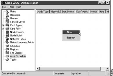
To create a new audit schedule, select Audit Schedule in the tree view and activate the New... right mouse menu from the list view popup menu, as shown in , "".
Figure 2-1 Audit Schedule List
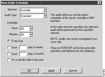
A New Audit Schedule dialog appears, as shown in , "".
Figure 2-2 New Audit Schedule
Select the network for which you want to schedule an audit and then select the type of audit required.
Note
The only type of audit available at this time is Standard.
The time for the audit is set using the Hours and Minutes pull-down boxes. The minute setting is restricted to ten-minute boundaries.
When selecting the day/date of the audit, there are four options:
•
Every day
•
On a specific day every week (0-6, Sunday= 0)
•
On a specific day every month
•
On the same day every year
If you choose to run the audit on the same day every year, the dialog displays a calendar on which to indicate the day you want the audit to run this year, as shown in , "".
Figure 2-3 Defining an Annual Audit
Once you complete the settings for this audit, press OK to save the record and close the dialog. If you decide not to create this new audit schedule, press Cancel to close the dialog.
Audit Schedule—Modify
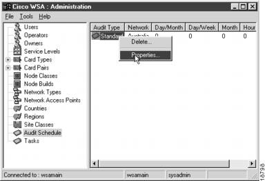
To modify an existing audit schedule, select Audit Schedule in the tree view and select the individual Audit Schedule that you want to modify. Then activate the Properties... right mouse menu from the item menu, as shown in , "".
Figure 2-4 Selecting an Audit Schedule for Modification
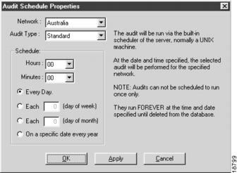
An Audit Schedule Properties dialog appears, as shown in , "".
Figure 2-5 Audit Schedule Properties
The properties of the audit schedule can be modified as described in the pervious section.
Once you complete the settings for this audit, press OK to save the record and close the dialog. If you decide not to modify the properties, press Cancel to close the dialog.
Audit Schedule—Delete
To delete an existing audit schedule, select Audit Schedule in the tree view and select the individual Audit Schedule that you want to delete. Then activate the Delete... right mouse menu from the item menu, as shown in , "".
Figure 2-6 Selecting an Audit Schedule for Deletion
A delete confirmation dialog appears. Press Yes to delete the audit schedule; press No if you decide not to delete the Audit Schedule.
Card Pairs
The following sections give detailed information about the Card Pairs object:
Card Pairs—Description
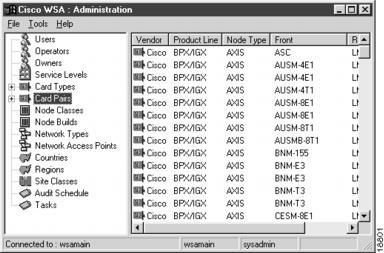
WSA holds details of all valid card pairings for the known node types. You can list these card pairs using the WSA System Administration Client, but you cannot create new ones or modify the properties of existing ones.
Card Pairs—Listing
To list the WSA Card Pairs, select Card Pairs from the tree view and drill down to a specific vendor and node type, as shown in , "".
Figure 2-7 Card Pairs List
Card Types
The following sections give detailed information about the Card Types object:
Card Types—Description
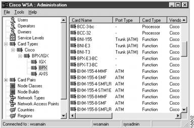
WSA holds details of all card types available for the known node types. You can list these card types using the WSA System Administration Client, but you cannot create new ones or modify the properties of existing ones.
Card Types—Listing
To list the WSA Card Types, select Card Types from the tree view and drill down to a specific vendor and node type, as shown in , "".
Figure 2-8 Card Types List
Countries
The following sections give detailed information about the Countries object:
Countries—Description
Network resources are located at geographical sites maintained by the WSA Explorer Client (refer to Cisco WAN Service Administrator Client User Guide). These locations must be in a specific country. The list of available countries is maintained by this application. The list of valid three-letter acronyms follows the International Standards Organization (ISO) 3166 A3.
Countries—Create
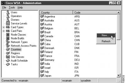
To create a new country, select Countries from the tree view and activate the New... right mouse menu from the list view popup menu, as shown in , "".
Figure 2-9 Countries List
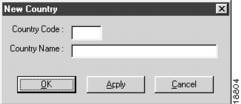
A New Country dialog appears, as shown in , "".
Figure 2-10 New Country
Enter the country code and name, for example, WAL and Wales. Use the valid three-letter acronyms specified in ISO 3166 A3.
Once you complete the settings for this country, press OK to save the record and close the dialog. If you decide not to create this new country, press Cancel to close the dialog.
Countries—Modify
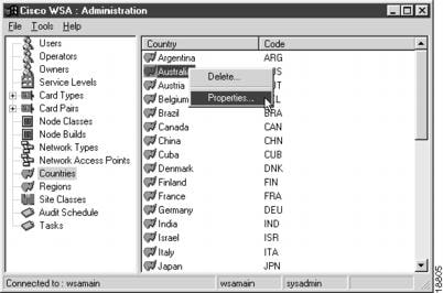
To modify an existing country, select Countries in the tree view and select the individual Country that you want to modify. Then activate the Properties... right mouse menu from the item menu, as shown in , "".
Figure 2-11 Selecting a Country for Modification
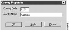
A Country Properties dialog appears, as shown in , "".
Figure 2-12 Country Properties
You can modify the country code and/or name. Use the valid three-letter acronyms specified in ISO 3166 A3.
Once you complete the settings for this country, press OK to save the record and close the dialog. If you decide not to modify the properties, press Cancel to close the dialog.
Countries—Delete
To delete a country, select Country in the tree view and select the individual Country that you want to delete. Then activate the Delete... right mouse menu from the item menu, as shown in , "".
Figure 2-13 Selecting a Country for Deletion
A delete confirmation dialog appears. Press Yes to delete the country; press No if you decide not to delete it.
Network Access Points
The following sections give detailed information about the Network Access Points object:
•
Network Access Points—Description
Network Access Points—Description
The WSA Control system connects to the networks it manages via the SV+ Service agent, which resides on a machine on the same local area network as the WSA server.
For the WSA Control system to be able to connect to the Service Agent, the host name, the IP address, and the login details of the server it resides on must be stored in the WSA database.
Network Access Points—Create
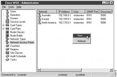
To create a new network access point, select Network Access Points from the tree view and activate the New... right mouse menu from the list view popup menu, as shown in , "".
Figure 2-14 Network Access Points List
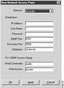
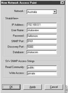
A New Network Access Point dialog appears, as shown in , "".
Figure 2-15 New Network Access Point
Appropriate information for the IP Address, User Name, and Password fields must be supplied.
If the Service Agent at this address is running on an SNMP Port, Discovery Port, or Database that does not match the supplied defaults, these values can be modified to match your configuration—as can the values for the SNMP Access Strings.
Once you complete the settings for this network access point, press OK to save the record and close the dialog. If you decide not to create this new network access point, press Cancel to close the dialog.
Network Access Points—Modify
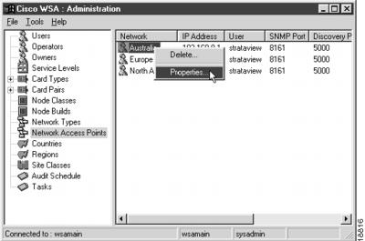
To modify an existing network access point, select Network Access Points in the tree view and select the individual Network Access Point that you want to modify. Then activate the Properties... right mouse menu from the item menu, as shown in , "".
Figure 2-16 Selecting a Network Access Point for Modification
A Network Access Point Properties dialog appears, as shown in , "".
Figure 2-17 Network Access Properties
Once you complete the settings for this network access point, press OK to save the record and close the dialog. If you decide not to modify the properties, press Cancel to close the dialog.
Network Access Points—Delete
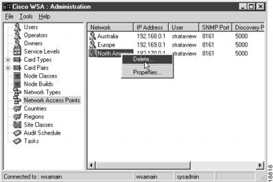
To delete a network access point, select Network Access Points in the tree view and select the individual Network Access Point that you want to delete. Then activate the Delete... right mouse menu from the item menu, as shown in , "".
Figure 2-18 Selecting a Network Access Point for Deletion
A delete confirmation dialog appears. Press Yes to delete the network access point; press No if you decide not to delete it.
Network Types
The following sections give detailed information about the Network Types object:
Network Types—Description
In WSA, the type of a network defines the types of nodes that can be created in it. The network types section of WSA System Administrator allows you to create, modify, and delete network types.
The built-in network type Cisco BPX/IGX allows all three supported node types (AXIS, BPX, and IGX) to exist in one network.
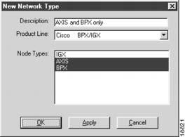
To create a network that contains only AXIS and BPX nodes, create a network type that does not allow IGX nodes and select this type when creating the network. When you create a node in this network, the selection of node types is restricted to the two types in its network type.
Network Types—Create
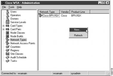
To create a new network type, select Network Types from the tree view and activate the New... right mouse menu from the list view popup menu, as shown in , "".
Figure 2-19 Network Type List
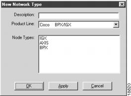
A New Network Type dialog appears, as shown in , "".
Figure 2-20 New Network Type
Enter a description for the network type and select a vendor's product line.
Note
In this release of Cisco WSA, Cisco is the only available vendor and BPX/IGX is the only available product line.
Select the node types that you want to be in this network type. A fully specified network type that only allows AXIS and BPX nodes appears, as shown in , "".
Figure 2-21 Node Type for AXIS and BPX Only
Once you complete the settings for this network type, press OK to save the record and close the dialog. If you decide not to create this new network type, press Cancel to close the dialog.
Network Types—Modify
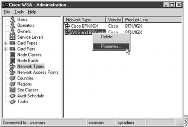
To modify an existing network type, select Network Types in the tree view and select the individual Network Type that you want to modify. Then activate the Properties... right mouse menu from the item menu, as shown in , "".
Figure 2-22 Selecting a Network Type for Modification
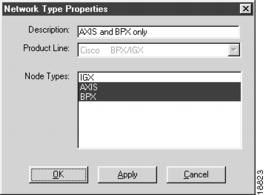
A Network Type Properties dialog appears, as shown in , "".
Figure 2-23 Network Type Properties
Note that the drop-down list box for selecting the vendor's product line is disabled. You can not change the vendor or product line for existing networks, because the WSA control system depends on this information to decide how to propagate messages to the network.
You can, however, modify the list of node types in this network type by selecting or deselecting items from the list. Making this modification has no effect on existing nodes in the network. It simply places a different restriction on the available node types when a new node is created in a network of this type.
Once you complete the settings for this network type, press OK to save the record and close the dialog. If you decide not to modify the properties, press Cancel to close the dialog.
Network Types—Delete
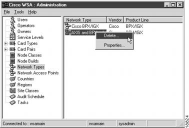
To delete a network type, select Network Types in the tree view and select the individual Network Type that you want to delete. Then activate the Delete... right mouse menu from the item menu, as shown in , "".
Figure 2-24 Selecting a Network Type for Deletion
A delete confirmation dialog appears. Press Yes to delete the network type; press No if you decide not to delete it.
Node Builds
The following sections give detailed information about the Node Builds object:
Node Builds—Description
When nodes are created, it is often desirable to have them preconfigured with a particular set of cards, rather than having all their slots empty and needing to add cards one by one or pair by pair using the Add Card Wizard in the WSA Explorer Client (refer to Cisco WAN Service Administrator Client User Guide).
WSA implements the ability to preconfigure a node using Node Builds.
Node Builds—Create
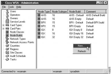
To create a new Node Build, select Node Builds from the tree view and activate the New... right mouse menu from the list view popup menu, as shown in , "".
Figure 2-25 Node Build List
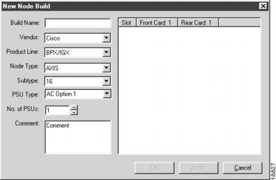
A New Node Build dialog appears, as shown in , "".
Figure 2-26 New Node Build
Enter a name for the build and select the Vendor, Product Line, Node Type, and Subtype.
Note
In this version of WSA, the only vendor and product line available is Cisco BPX/IGX.
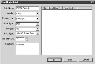
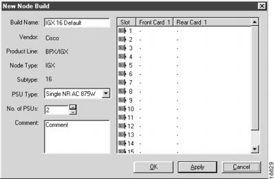
Select a PSU type and set the number of PSUs to install. Once these seven items have been entered and/or selected, you can add an optional comment. Then a dialog appears similar to , "".
Figure 2-27 Defining the Node Build—Step 1
Press Apply and the new Node Build is created in the database. Once the record has been inserted, the dialog changes appearance slightly to that shown in , "".
Figure 2-28 Defining the Node Build—Step 2
Note that the vendor, product line, node type, and subtype have become noneditable and the relevant number of slot records is displayed in the list view.
At this point, you can close the dialog and have a valid Node Build, but it would be empty, that is it would have no cards defined.
To add cards to the Node Build, select the slot to which you want to add the card and activate the Add... right mouse menu from the list view popup menu, as shown in , "".
Figure 2-29 Selecting a Slot to Add a Card Type to the Node Build
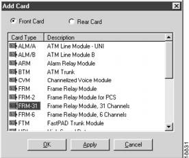
An Add Card dialog appears, as shown in , "".
Figure 2-30 Adding Card Types to the Node Build
With the Front Card radio button selected, select a front card to insert into the slot you selected in the Node Build, and press Apply. Select the Rear Card radio button, select a rear card, and press Apply again. Then press Cancel to close the dialog or OK to insert the card and close the dialog.
CautionWhen adding card types to slots in the node build, you must be aware of which front cards can safely reside with which rear cards. The card pair information described in section Card Pairs is NOT used by this dialog. It is your responsibility to ensure that card pairings in a node build are valid.
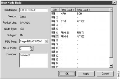
Once a few cards have been added to the Node Build, it appears similar to , "".
Figure 2-31 Populated Node Build
Once you complete the cards in this Node Build, press OK to save the record and close the dialog. If you decide not to add these cards to the Node Build, press Cancel to close the dialog.
Node Builds—Modify
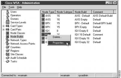
To modify an existing Node Build, select Node Builds in the tree view and select the individual Node Build that you want to modify. Then activate the Properties... right mouse menu from the item menu, as shown in , "".
Figure 2-32 Selecting a Node Build for Modification
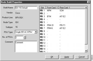
A Node Build Properties dialog appears, as shown in , "".
Figure 2-33 Node Build Properties
New cards can be added to the Node Build by using the same techniques described in section Node Builds—Create.
Once you complete the settings for this Node Build, press OK to save the record and close the dialog. If you decide not to modify the properties, press Cancel to close the dialog.
Node Builds—Delete
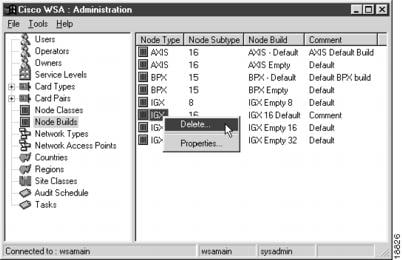
To delete a Node Build, select Node Builds in the tree view and select the individual Node Build that you want to delete. Then activate the Delete... right mouse menu from the item menu, as shown in , "".
Figure 2-34 Selecting a Node Build for Deletion
A delete confirmation dialog appears. Press Yes to delete the Node Build; press No if you decide not to delete it.
Node Classes
The following sections give detailed information about the Node Classes object:
Node Classes—Description
Node classes are arbitrary text strings that have an implied meaning only in your business. Node Classes have no significance in WSA other than as a label, but you must define at least one Node Class to be able to create nodes in WSA.
Node Classes—Create
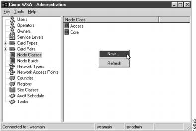
To create a new Node Class, select Node Class from the tree view and activate the New... right mouse menu from the list view popup menu, as shown in , "".
Figure 2-35 Node Class List
A New Node Class dialog appears, as shown in , "".
Figure 2-36 New Node Class
Enter a description for the node class.
Once you complete the settings for this Node Class, press OK to save the record and close the dialog. If you decide not to create this new Node Class, press Cancel to close the dialog.
Node Classes—Modify
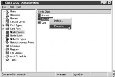
To modify an existing Node Class, select Node Class in the tree view and select the individual Node Class that you want to modify. Then activate the Properties... right mouse menu from the item menu, as shown in , "".
Figure 2-37 Selecting a Node Class for Modification
A Node Class Properties dialog appears, as shown in , "".
Figure 2-38 Node Class Properties
Once you complete the settings for this Node Class, press OK to save the record and close the dialog. If you decide not to modify the properties, press Cancel to close the dialog.
Node Classes—Delete
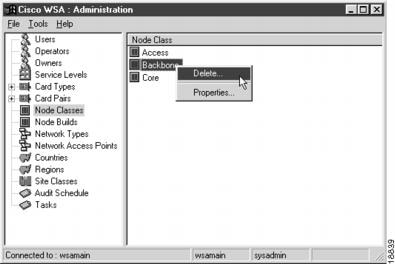
To delete a Node Class, select Node Class in the tree view and select the individual Node Class that you want to delete. Then activate the Delete... right mouse menu from the item menu, as shown in , "".
Figure 2-39 Selecting a Node Class for Deletion
A delete confirmation dialog appears. Press Yes to delete the Node Class; press No if you decide not to delete it.
Operators
The following sections give detailed information about the Operators object:
Operators—Description
Operators are the organizations that own the networks controlled by WSA. At least one operator must exist for WSA to function correctly.
Operators—Create
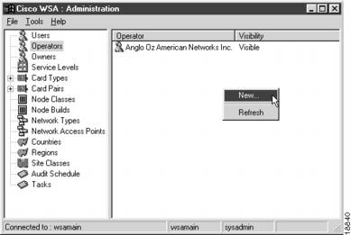
To create a new Operator, select Operators from the tree view and activate the New... right mouse menu from the list view popup menu, as shown in , "".
Figure 2-40 Operator List
A New Operator dialog appears, as shown in , "".
Figure 2-41 New Operator
Enter the operator name. Check the Hidden box if you do not want this operator to be available for selection when adding a network to the system using the Add Network Wizard in the WSA Explorer Client (refer to Cisco WAN Service Administrator Client User Guide).
Once you complete the settings for this Operator, press OK to save the record and close the dialog. If you decide not to create this new Operator, press Cancel to close the dialog.
Operators—Modify
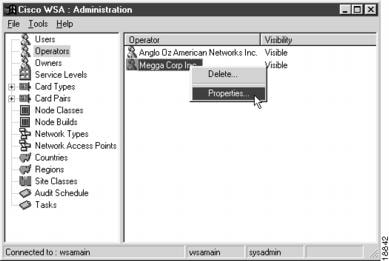
To modify an existing Operator, select Operators in the tree view and select the individual Operator that you want to modify. Then activate the Properties... right mouse menu from the item menu, as shown in , "".
Figure 2-42 Selecting an Operator for Modification
An Operator Properties dialog appears, as shown in , "".
Figure 2-43 Operator Properties
Once you complete the settings for this Operator, press OK to save the record and close the dialog. If you decide not to modify the properties, press Cancel to close the dialog.
Operators—Delete
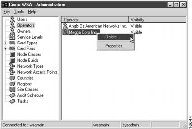
To delete an Operator, select Operators in the tree view and select the individual Operator that you want to delete. Then activate the Delete... right mouse menu from the item menu, as shown in , "".
Figure 2-44 Selecting an Operator for Deletion
A delete confirmation dialog appears. Press Yes to delete the Operator; press No if you decide not to delete it.
Owners
The following sections give detailed information about the Owners object:
Owners—Description
The following entities within WSA have ownership rules applied to them, where ownership implies responsibility for and authority over the specific entity:
•
Accounts (Customers)
•
Contracts
•
Customer Projects
•
Locations (Sites)
•
Network Projects
•
Networks
•
Nodes
A single owner can be allowed to own all, some, or none of these entities. For example, you may want to create a sales department owner that is allowed to own accounts, projects, and contracts, an engineering owner who is allowed to own networks, nodes, and projects, and a facilities owner who is only allowed to own locations.
Owners—Create
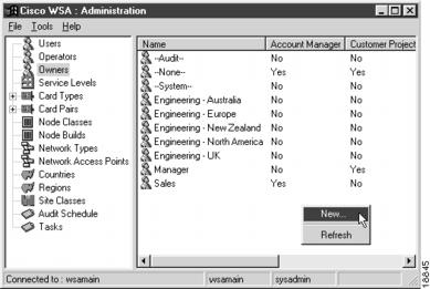
To create a new Owner, select Owners from the tree view and activate the New... right mouse menu from the list view popup menu, as shown in , "".
Figure 2-45 Owners List
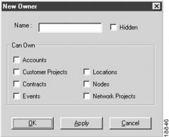
A New Owner dialog appears, as shown in , "".
Figure 2-46 New Owner
Enter the name of the new Owner and check the appropriate boxes to indicate the WSA entities for which this owner can take responsibility.
Once you complete the settings for this Owner, press OK to save the record and close the dialog. If you decide not to create this new Owner, press Cancel to close the dialog.
Owners—Modify
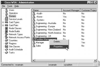
To modify an existing Owner, select Owners in the tree view and select the individual Owner that you want to modify. Then activate the Properties... right mouse menu from the item menu, as shown in , "".
Figure 2-47 Selecting an Owner for Modification
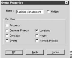
An Owner Properties dialog appears, as shown in , "".
Figure 2-48 Owner Properties
Once you complete the settings for this Owner, press OK to save the record and close the dialog. If you decide not to modify the properties, press Cancel to close the dialog.
Owners—Delete
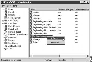
To delete an Owner, select Owners in the tree view and select the individual Owner that you want to delete. Then activate the Delete... right mouse menu from the item menu, as shown in , "".
Figure 2-49 Selecting an Owner for Deletion
A delete confirmation dialog appears. Press Yes to delete the Owner; press No if you decide not to delete it.
Regions
The following sections give detailed information about the Regions object:
Regions—Description
In WSA, Regions are used to group together nodes in a network by some common attribute. Typically this grouping will be on a geographical basis—all the nodes in France, Germany, and Italy being in the Europe region, for example.
Regions can, however, be used to group nodes together by some other common attribute, for example, the node class. In this example, and assuming that you have two node classes, access and core, you can create an Access Nodes and a Core Nodes region to separate the two types.
WSA users are restricted to viewing nodes that are in Regions for which they have been granted permissions (refer to the section Users).
Regions—Create
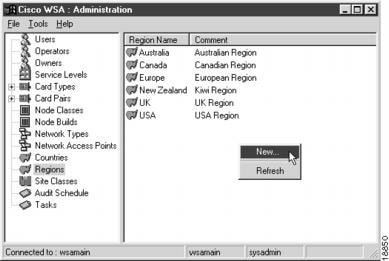
To create a new Region, select Regions from the tree view and activate the New... right mouse menu from the list view popup menu, as shown in , "".
Figure 2-50 Regions List
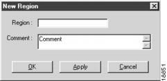
A New Region dialog appears, as shown in , "".
Figure 2-51 New Region
Once you complete the settings for this Region, press OK to save the record and close the dialog. If you decide not to create this new Region, press Cancel to close the dialog.
Regions—Modify
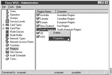
To modify an existing Region, select Regions in the tree view and select the individual Region that you want to modify. Then activate the Properties... right mouse menu from the item menu, as shown in , "".
Figure 2-52 Selecting a Region for Modification
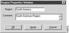
A Region Properties dialog appears, as shown in , "".
Figure 2-53 Region Properties
Once you complete the settings for this Region, press OK to save the record and close the dialog. If you decide not to modify the properties, press Cancel to close the dialog.
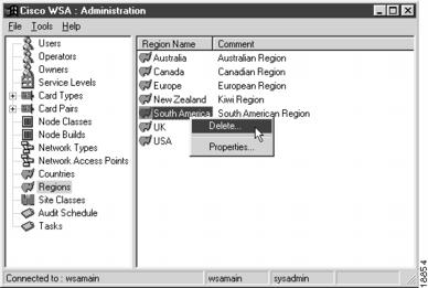
Regions—Delete
To delete a Region, select Regions in the tree view and select the individual Region that you want to delete. Then activate the Delete... right mouse menu from the item menu, as shown in , "".
Figure 2-54 Selecting a Region for Deletion
A delete confirmation dialog appears. Press Yes to delete the Region; press No if you decide not to delete it.
Service Levels
The following sections give detailed information about the Service Levels object:
Service Levels—Description
Service Levels are the top level item for Quality of Service settings within WSA. They provide two main functions:
•
Group templates together.
•
Define the default connection subtype for multi-segment connections.
Templates are described in more detail in "".
The default connection subtypes defined by the Service Level are used when a connection goes across one or more Network to Network Interconnects (NNIs).
If, for example, a Frame Relay connection is requested and it is routed via an ATM NNI, then the connection subtype for the two ATM to Frame Relay Interworking Permanent Virtual Circuits (PVCs) created is defined by the Service Level chosen for the connection.
Service Levels—Create
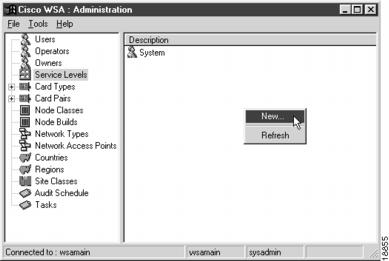
To create a new Service Level, select Service Levels from the tree view and activate the New... right mouse menu from the list view popup menu, as shown in , "".
Figure 2-55 Service Level List
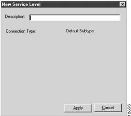
A New Service Level dialog appears, as shown in , "".
Figure 2-56 New Service Level—Step 1
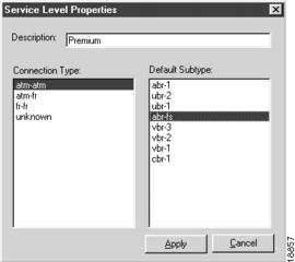
Enter a description for the service level and press Apply. Once the record has been inserted into the database, the dialog changes appearance to that shown in , "".
Figure 2-57 New Service Level—Step 2
You must now select each available connection type in turn and assign it a default subtype by selecting from the right list. After each assignment, press Apply.
Once you complete the settings for this Service Level, press Cancel to close the dialog.
Service Levels—Modify
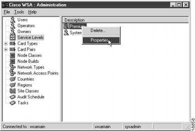
To modify an existing Service Level, select Service Levels in the tree view and select the individual Service Level that you want to modify. Then activate the Properties... right mouse menu from the item menu, as shown in , "".
Figure 2-58 Selecting a Service Level for Modification
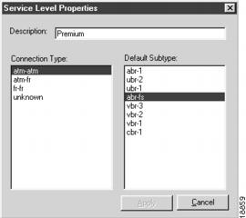
A Service Level Properties dialog appears, as shown in , "".
Figure 2-59 Service Level Properties
You can change the description of the service level and/or modify the default connection subtype for a given connection type as described in the previous section.
Once you complete the settings for this Service Level, press Cancel to close the dialog.
Service Levels—Delete
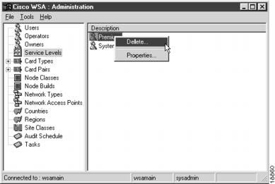
To delete a Service Level, select Service Levels in the tree view and select the individual Service Level that you want to delete. Then activate the Delete... right mouse menu from the item menu, as shown in , "".
Figure 2-60 Selecting a Service Level for Deletion
A delete confirmation dialog appears. Press Yes to delete the Service Level; press No if you decide not to delete it.
Site Classes
The following sections give detailed information about the Site Classes object:
Site Classes—Description
Site Classes are arbitrary text labels assigned to locations when they are created. At least one site class must exist for WSA to work correctly.
Site Classes—Create
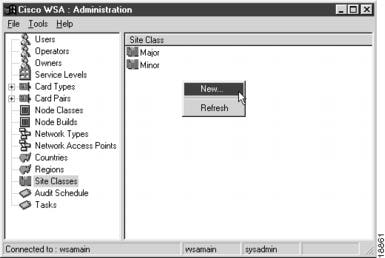
To create a new Site Class, select Site Classes from the tree view and activate the New... right mouse menu from the list view popup menu, as shown in , "".
Figure 2-61 Site Class List
A New Site Class dialog appears, as shown in , "".
Figure 2-62 New Site Class
Enter the Site Class name and press OK to save the record and close the dialog. If you decide not to create this new Site Class, press Cancel to close the dialog.
Site Classes—Modify
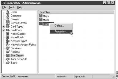
To modify an existing Site Class, select Site Classes in the tree view and select the individual Site Class that you want to modify. Then activate the Properties... right mouse menu from the item menu, as shown in , "".
Figure 2-63 Selecting a Site Class for Modification
A Site Class Properties dialog appears, as shown in , "".
Figure 2-64 Site Class Properties
Once you complete the settings for this Site Class, press OK to save the record and close the dialog. If you decide not to modify the properties, press Cancel to close the dialog.
Site Classes—Delete
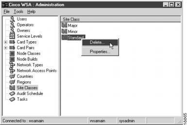
To delete a Site Class, select Site Classes in the tree view and select the individual Site Class that you want to delete. Then activate the Delete... right mouse menu from the item menu, as shown in , "".
Figure 2-65 Selecting a Site Class for Deletion
A delete confirmation dialog appears. Press Yes to delete the Site Class; press No if you decide not to delete it.
Tasks
The following sections give detailed information about the Tasks object:
Tasks—Description
The WSA Control System creates tasks that are acted on to provision services within the networks controlled by WSA. These tasks can be listed in the WSA System Administrator Client. They can be deleted and the properties of the WSA entity they relate to can be viewed.
Note
In this version of WSA, the only entity that a task can relate to is a PVC. Therefore, when you view the properties of the tasks related entity, you will see the properties of the connection of which the PVC is a part.
Tasks—View Properties
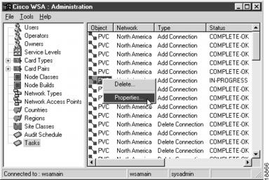
To view a Task, select Tasks from the tree view and select the individual Task that you want to view. Then activate the Properties... right mouse menu from the list view popup menu, as shown in , "".
Figure 2-66 Task List
If the task relates to a PVC that is no longer in the database, a warning dialog appears, as shown in , "".
Figure 2-67 Task Warning
If the PVC relates to an existing connection, the properties dialog for that connection appears (refer to Cisco WAN Service Administrator Client User Guide).
Tasks—Delete
To delete a Task, select Tasks in the tree view and select the individual Task that you want to delete. Then activate the Delete... right mouse menu from the item menu, as shown in , "".
Figure 2-68 Selecting a Task for Deletion
A delete confirmation dialog appears. Press Yes to delete the Task; press No if you decide not to delete it.
Users
The following sections give detailed information about the Users object:
Users—Description
Users are the individuals who will be using the WSA PC Clients. They are allocated a unique login name and access to the system is password protected. Visibility of nodes within networks and regions is controlled via the user account.
Users—Create
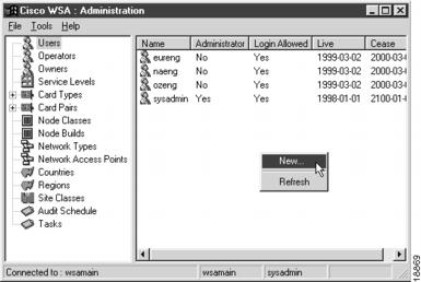
To create a new User, select Users from the tree view and activate the New... right mouse menu from the list view popup menu, as shown in , "".
Figure 2-69 User List
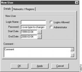
A New User dialog appears, as shown in , "".
Figure 2-70 New User
Enter the login name, which must be a minimum of 3 characters, and the password, which must be a minimum of 8 characters and a maximum of 16 characters.
Modify the start date and end dates—outside the boundaries of which this user will not be able to log into WSA—and check the Logins Allowed box if you want this account to be immediately active. Check the Administrator box if this user is to be given access to the WSA System Administration Client—this application.
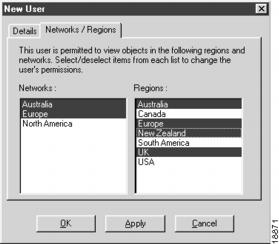
Next, activate the Networks / Regions tab and select one or more networks and one or more regions for user access, as shown in , "".
Figure 2-71 Assigning Networks and Regions
When this user logs into WSA, it will only be able to view nodes in the networks and regions selected here. All other nodes are hidden from view.
Once you complete the settings for this User, press OK to save the record and close the dialog. If you decide not to create this new User, press Cancel to close the dialog.
Note
For this new user account to be usable, be sure to check Logins Allowed and give the user permissions on at least one network and region.
Users—Modify
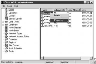
To modify an existing User, select Users in the tree view and select the individual User that you want to modify. Then activate the Properties... right mouse menu from the item menu, as shown in , "".
Figure 2-72 Selecting a User for Modification
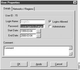
A User Properties dialog appears, as shown in , "".
Figure 2-73 User Properties
Note
The login name is now disabled. Once the user has been created, its name can not be changed.
Once you complete the settings for this User, press OK to save the record and close the dialog. If you decide not to modify the properties, press Cancel to close the dialog.
Users—Delete
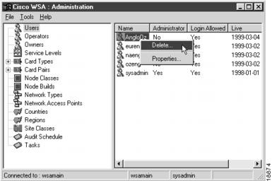
To delete a User, select Users in the tree view and select the individual User that you want to delete. Then activate the Delete... right mouse menu from the item menu, as shown in , "".
Figure 2-74 Selecting a User for Deletion
A delete confirmation dialog appears. Press Yes to delete the User; press No if you decide not to delete it.
