[an error occurred while processing this directive]

Support

Chapter 9, Circuits and Tunnels

 Feedback

Table Of Contents

Circuits and Tunnels

9.1 Circuit Properties

9.1.1 Circuit Status

9.1.2 Circuit States

9.1.3 Circuit Protection Types

9.1.4 Viewing Circuit Information on the Edit Circuit Window

9.2 Managing Cross-Connect Card Bandwidth

9.3 DCC Tunnels

9.4 Multiple Drops for Unidirectional Circuits

9.5 Monitor Circuits

9.6 Path Protection Configuration Circuits

9.7 BLSR Protection Channel Circuits

9.8 Path Trace

9.9 Path Signal Label, C2 Byte

9.10 Automatic Circuit Routing

9.10.1 Bandwidth Allocation and Routing

9.10.2 Secondary Sources and Drops

9.11 Manual Circuit Routing

9.12 Constraint-Based Circuit Routing


Circuits and Tunnels


Note The terms "Unidirectional Path Switched Ring" and "UPSR" may appear in Cisco literature. These terms do not refer to using Cisco ONS 15xxx products in a unidirectional path switched ring configuration. Rather, these terms, as well as "Path Protected Mesh Network" and "PPMN," refer generally to Cisco's path protection feature, which may be used in any topological network configuration. Cisco does not recommend using its path protection feature in any particular topological network configuration.


This chapter explains Cisco ONS 15454 STS and VT circuits and VT and DCC tunnels. To provision circuits and tunnels, refer to the Cisco ONS 15454 Procedure Guide.

Chapter topics include:

Circuit Properties

Managing Cross-Connect Card Bandwidth

DCC Tunnels

Multiple Drops for Unidirectional Circuits

Monitor Circuits

Path Protection Configuration Circuits

BLSR Protection Channel Circuits

Path Trace

Automatic Circuit Routing

Manual Circuit Routing

Constraint-Based Circuit Routing

9.1 Circuit Properties

On the ONS 15454 you can create unidirectional and bidirectional circuits. For path protection configuration circuits, you can create revertive or non revertive circuits. Circuits will route automatically or you can manually route them. With the autorange feature, you do not need to individually build multiple circuits of the same type; CTC can create additional sequential circuits if you specify the number of circuits you need and build the first circuit.

You can provision circuits either before or after cards are installed if the ONS 15454 slots are provisioned for the card that will carry the circuit. However, circuits will not carry traffic until the cards are installed and the ports and circuit status is IS, OOS-AINS, or OOS-MT.

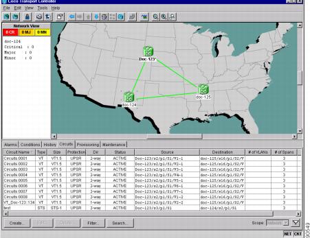
The ONS 15454 Circuits window (Figure 9-1), which is displayed in network, node, and card view, is where you can view information about circuits, including:

Name—Name of the circuit. The circuit name can be manually assigned or automatically generated.

Type—Circuit types are: STS (STS circuit) VT (VT circuit), VTT (VT tunnel), or VAP (VT aggregation point).

Size—Circuit size. VT circuits are 1.5. STS circuit sizes are 1, 3c, 6c, 9c, 12c, 24c, 48c, or 192c.

Protection—The type of circuit protection. See the "Circuit Protection Types" section.

Direction—The circuit direction, either two-way or one-way.

Status—The circuit status. See the "Circuit Status" section.

Source—The circuit source in the format: node/slot/port "port name"/STS/VT. (Port name will appear in quotes.) Node and slot will always display; port "port name"/STS/VT might display, depending on the source card, circuit type, and whether a name is assigned to the port. If the circuit size is a concatenated size (3c, 6c, 12c, etc.) STSs used in the circuit will be indicated by an ellipsis, for example, "S7..9," (STSs 7, 8, and 9) or S10..12 (STS 10, 11, and 12).

Destination—The circuit destination in same format (node/slot/port "port name"/STS/VT) as the circuit source.

# of VLANS—The number of VLANS used by an Ethernet circuit.

# of Spans—The number of inter-node links that constitute the circuit. Right-clicking the column displays a shortcut menu from which you can choose to show or hide circuit span detail.

State—The circuit state. See the "Circuit Status" section.

Figure 9-1 ONS 15454 Circuit Window in Network View

9.1.1 Circuit Status

The circuit statuses that display in the Circuit window Status column are generated by CTC based on conditions along the circuit path. Table 9-1 shows the statuses that can appear in the Status column.

Table 9-1 ONS 15454 Circuit Status 

Status
Definition/Activity

CREATING

CTC is creating a circuit.

ACTIVE

CTC created a circuit. All components are in place and a complete path exists from circuit source to destination.

DELETING

CTC is deleting a circuit.

INCOMPLETE

A CTC-created circuit is missing a cross-connect or network span; a complete path from source to destination(s) does not exist, or an Alarm Interface Panel (AIP) change occurred on one of the circuit nodes and the circuit is in need of repair. (AIPs store the node MAC address.)

In the CTC, circuits are represented using cross-connects and network spans. If a network span is missing from a circuit, the circuit status is INCOMPLETE. However, an INCOMPLETE status does not necessarily mean a circuit traffic failure has occurred, for traffic may flow on a protect path.

Network spans are in one of two states: up or down. On CTC circuit and network maps, up spans are displayed as green lines, and down spans are displayed as gray lines. If a failure occurs on a network span during a CTC session, the span remains in on the network map but its color changes to gray to indicate the span is down. If you restart your CTC session while the failure is active, the new CTC session cannot discover the span and its span line will not display on the network map.

Subsequently, circuits routed on a network span that goes down will display as ACTIVE during the current CTC session, but they will display as INCOMPLETE to users who log in after the span failure.

UPGRADABLE

A TL1-created circuit or a TL1-like CTC-created circuit is complete and has upgradable cross-connects. A complete path from source to destination(s) exists. The circuit can be upgraded.

INCOMPLETE_UPGRADABLE

A TL1-created circuit or a TL1-like CTC-created circuit with upgradable cross-connects is missing a cross-connect or circuit span (network link), and a complete path from source to destination(s) does not exist. The circuit cannot be upgraded until missing components are in place.

NOT_UPGRADABLE

A TL1-created circuit or a TL1-like CTC-created circuit is complete but has at least one non-upgradable cross-connect. UPSR_HEAD, UPSR_EN, UPSR_DC, and UPSR_DROP connections are not upgradable, so all unidirectional path protection configuration circuits created with TL1 are not upgradable.

INCOMPLETE_NOT_UPGRADABLE

A TL1-created circuit or a TL1-like CTC-created circuit with one or more non-upgradable cross-connects is missing a cross-connect or circuit span (network link); a complete path from source to destination(s) does not exist.


9.1.2 Circuit States

State is a user-assigned designation that indicates whether the circuit should be in service or out of service. The states that you can assign to circuits are shown in Table 9-2. To carry traffic, circuits must have a status of Active and a state of In Service (IS), Out of Service Auto in Service (OOS_AINS), or Out of Service Maintenance (OOS_MT). The circuit source port and destination port must also be IS, OOS_AINS, or OOS_MT.


Note OOS_AINS and OOS_MT allow a signal to be carried, although alarms are suppressed.


You can assign a state to circuits at two points:

During circuit creation you assign a state to the circuit on the Create Circuit wizard.

After circuit creation, you can change a circuit state on the Edit Circuit window.

Table 9-2 Circuit States 

State
Definition

IS

In service; able to carry traffic.

OOS

Out of service; unable to carry traffic.

OOS-AINS

Out of service, auto in service; alarm reporting is suppressed, but traffic is carried and loopbacks are allowed. Raised fault conditions, whether their alarms are reported or not, can be retrieved on the CTC Conditions tab or by using the TL1 RTRV-COND command. VT circuits generally switch to IS when source and destination ports are IS, OOS_AINS, or OOS_MT regardless of whether a physical signal is present. STS circuits switch to IS when a signal is received.

OOS-MT

Out of service, maintenance; alarm reporting is suppressed, but traffic is carried and loopbacks are allowed. Raised fault conditions, whether their alarms are reported or not, can be retrieved on the CTC Conditions tab or by using the TL1 RTRV-COND command.


PARTIAL is appended to a circuit state whenever all circuit cross-connects are not in the same state. Table 9-3 shows the partial circuit states that can display.

Table 9-3 Partial Circuit States

State
Definition

OOS_PARTIAL

At least one connection is OOS and at least one other is in some other state.

OOS_AINS_PARTIAL

At least one connection is OOS_AINS and at least one other is in IS state.

OOS_MT_PARTIAL

At least one connection is OOS_MT and at least one other is in some other state except OOS.


PARTIAL states can occur during automatic or manual transitions. OOS_AINS_PARTIAL displays if you assign OOS_AINS to a circuit with DS-1 or DS3XM cards as the source or destination. Some cross-connects transition to IS, while others are OOS_AINS. PARTIAL can appear during a manual transition caused by an abnormal event such as a CTC crash, communication error, or one of the cross-connects could not be changed. Refer to the Cisco ONS 15454 Troubleshooting Guide for troubleshooting procedures.

Circuits do not use the soak timer for transitional states, but ports do. When provisioned as OOS-AINS, the ONS 15454 monitors a circuit's cross-connects for an error-free signal. It changes the state of the circuit from OOS-AINS to IS or to AINS-partial as each cross-connect assigned to the circuit path is completed. This allows you to provision a circuit using TL1, verify its path continuity, and prepare the port to go into service when it receives an error-free signal for the time specified in the port soak timer. Two common examples of state changes you will see when provisioning DS-1 and DS-3 circuits using CTC are as follows:

When provisioning VT1.5 circuits and VT tunnels as OOS-AINS, the circuit state transitions to IS shortly after the circuits are created with the circuit source and destination ports are IS, OOS_AINS, or OOS_MT. The source and destination ports on the VT1.5 circuits remain in OOS-AINS state until an alarm-free signal is received for the duration of the soak timer. When the soak timer expires, the VT1.5 source port and destination port states change to IS.

When provisioning STS circuits as OOS-AINS, the circuit and source and destination ports are OOS-AINS. As soon as an alarm-free signal is received the circuit state changes to IS and the source and destination ports remain OOS-AINS for the duration of the soak timer. After the port soak timer expires, STS source and destination ports change to IS.

9.1.3 Circuit Protection Types

The Protection column on the Circuit window shows the card (line) and SONET topology (path) protection used for the entire circuit path. Table 9-4 shows the protection type indicators that you will see in this column.

Table 9-4 Circuit Protection Types 

Protection Type
Description

Circuit protection is not applicable.

2F BLSR

The circuit is protected by a 2-fiber bidirectional line switched ring (BLSR).

4F BLSR

The circuit is protected by a 4-fiber BLSR.

BLSR

The circuit is protected by a both a 2-fiber and a 4-fiber BLSR.

Path Protection Configuration

The circuit is protected by a path protection configuration.

1+1

The circuit is protected by a 1+1 protection group.

Protected

The circuit is protected by diverse SONET topologies, for example, a BLSR and a path protection configuration, or a path protection configuration and 1+1.

2F-PCA

The circuit is routed on a protection channel access path on a 2-fiber BLSR. PCA circuits are unprotected.

4F-PCA

The circuit is routed on a protection channel access path on a 4-fiber BLSR. PCA circuits are unprotected.

PCA

The circuit is routed on a protection channel access path on both 2-fiber and 4-fiber BLSRs. PCA circuits are unprotected.

Unprot (black)

The circuit is not protected.

Unprot (red)

A circuit created as a fully-protected circuit is no longer protected due to a system change, such as a traffic switch.

Unknown

Circuit protection types display in the Protection column only when all circuit components are known, that is, when the circuit status is ACTIVE or UPGRADABLE. If the circuit is in some other status, protection type is displayed as "unknown."


9.1.4 Viewing Circuit Information on the Edit Circuit Window

The detailed circuit map displayed on the Edit Circuit window allows you to view information about ONS 15454 circuits. Routing information that is displayed includes:

Circuit direction (unidirectional/bidirectional)

The nodes, STSs, and VTs through which circuit passes including slots and port numbers

The circuit source and destination points

OSPF Area IDs

Link protection (path protection configuration, unprotected, BLSR, 1+1) and bandwidth (OC-N)

For BLSRs, the detailed map shows the number of BLSR fibers and the BLSR Ring ID. For path protection configurations, the map shows the active and standby paths from circuit source to destination, and it also shows the working and protect paths.

Alarms and states can also be viewed on the circuit map, including:

Alarm states of nodes on the circuit route

Number of alarms on each node organized by severity

Port service states on the circuit route

Alarm state/color of most severe alarm on port

Loopbacks

Path trace states

Path selectors states

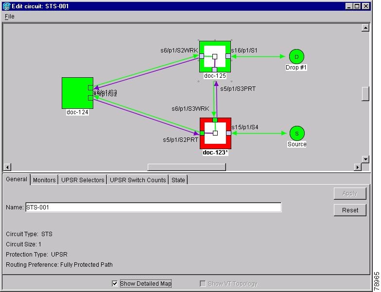
Figure 9-2 shows a bidirectional STS circuit routed on a path protection configuration.

Figure 9-2 Path Protection Configuration Circuit Displayed on the Detailed Circuit Map

By default, the working path is indicated by a green, bidirectional arrow, and the protect path is indicated by a purple, bidirectional arrow. Source and destination ports are shown as circles with an S and D. Port states are indicated by colors, shown in Table 9-5.

Table 9-5 Port State Color Indicators

Port Color
State

Green

IS

Gray

OOS

Purple

OOS-AINS

Light blue

OOS-MT


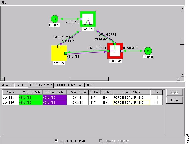
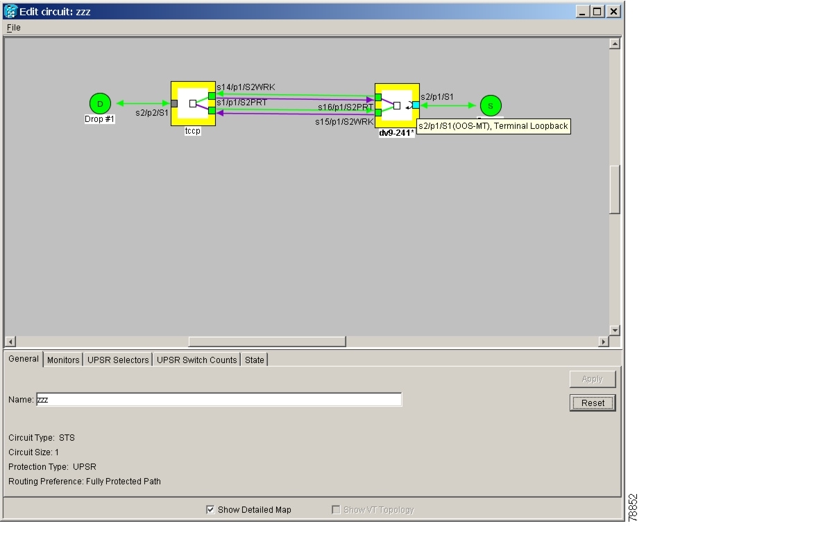
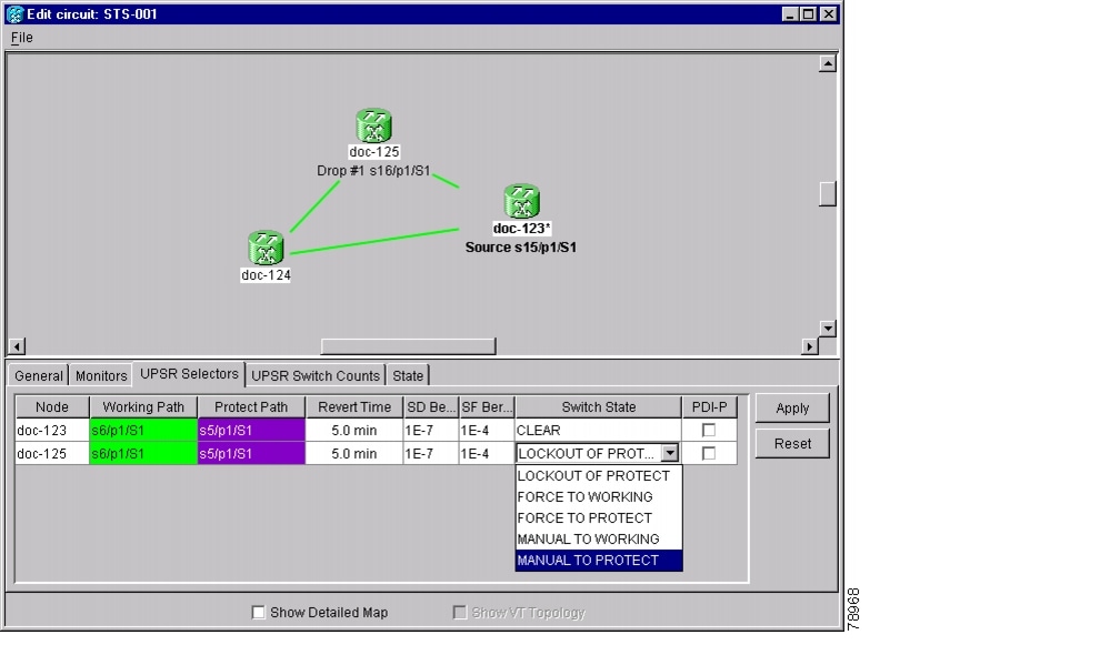
Notation within the squares on each node indicate switches and other conditions. A Path Protection Configuration Force switch is shown in Figure 9-3, and an active path trace is shown in Figure 9-4.

Figure 9-3 Detailed Circuit Map Showing a Path Protection Configuration Circuit

Figure 9-4 Detailed Circuit Map Showing a Path Trace

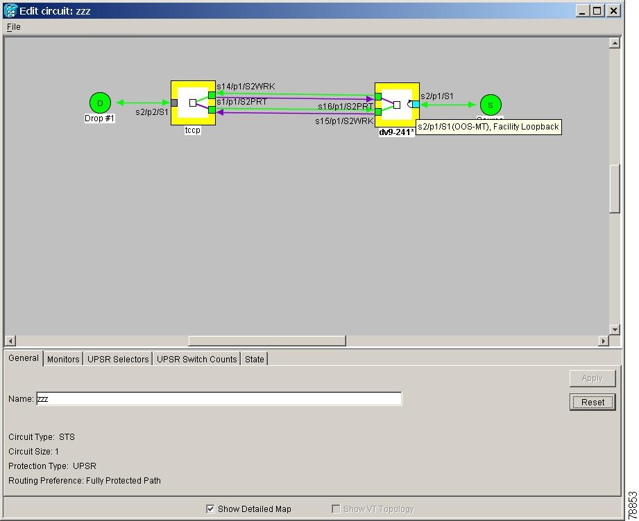
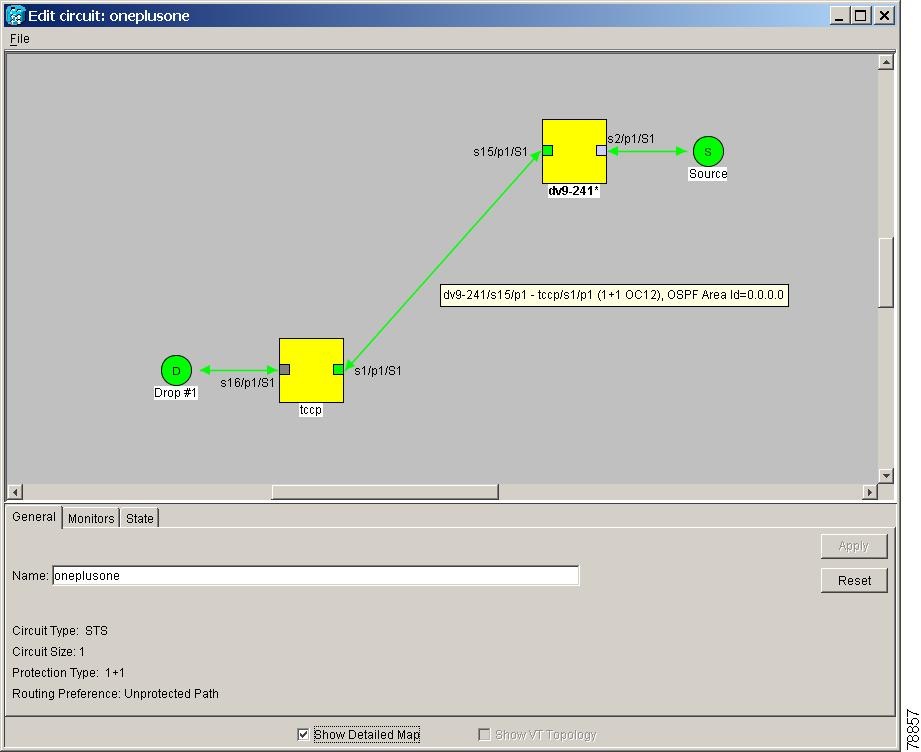
The detailed circuit map shows facility loopbacks (shown in Figure 9-5) and terminal loopbacks (shown in Figure 9-6).

Figure 9-5 Detailed Circuit Map Showing a Facility Loopback

Figure 9-6 Detailed Circuit Map Showing a Terminal Loopback

Move the mouse cursor over nodes, ports, and spans to see tooltips with information including the number of alarms on a node (organized by severity), a port's state of service (that is, in-service, out-of-service), and the protection topology. Figure 9-7 shows a tooltip displayed for a BLSR span.

Figure 9-7 Detailed Circuit Map Showing BLSR Span Information

Right-click a node, port, or span on the detailed circuit map to initiate certain circuit actions:

Right-click a unidirectional circuit destination node to add a drop to the circuit.

Right-click a port containing a path trace capable card to initiate the path trace.

Right-click a path protection configuration span to change the state of the path selectors in the path protection configuration circuit.

Figure 9-8 shows an example of the information that can be displayed. From this example, you can determine:

The circuit has one source and one destination.

The circuit has three nodes in its route; the state of the most severe alarm can be determined by the color of the node icons, for example, yellow indicates the most severe alarm is minor in severity.

The STSs and ports that the circuit passes through from source to destination.

The port states and severity of the most severe alarm on each port.

A facility loopback exists on the port at one end of the circuit; a terminal loopback exists at the other end port.

An automatic path trace exists on one STS end of the circuit; a manual path trace at the other STS end.

The circuit is path protection configurationprotected (by path selectors). One path selector has a Lockout, one has a Force switch, one has a Manual switch, and the others are free of external switch commands.

The working path (green) flows from ptlm6-454a59-24/s6/p1/S1 to dv9-241/s6/p1/S1, and from dv9-241/s16/p1/S1 to tccp/s14/p1/vc3-3. The protect path (purple) is also visible.

On ptlm6-454a59-24 and tccp, the working path is active; on dv9-241, the protect path is active.

From the example, you could:

Display any port or node view

Edit the path trace states of any port that supports path trace

Change the path selector state of any path protection configuration path selector

Figure 9-8 Detailed Circuit Map Showing a Terminal Loopback

9.2 Managing Cross-Connect Card Bandwidth

The ONS 15454 XC, XCVT, XC10G cross-connect cards perform port-to-port, time-division multiplexing (TDM). XC cards perform STS multiplexing only. XCVT and XC10G cards perform STS and VT1.5 multiplexing.

The STS matrix on the XC and XCVT cross-connect cards has a capacity for 288 STS terminations, and the XC10G has a capacity for 1152 STS terminations. Because each STS circuit requires a minimum of two terminations, one for ingress and one for egress, the XC and XCVT have a capacity for 144 STS circuits, and the XC10G has a capacity for 576 STS circuits. However, this capacity is reduced at path protection configuration and 1+1 nodes because three STS terminations are required at circuit source and destination nodes and four terminations at path protection configuration and 1+1 circuit pass-through nodes.

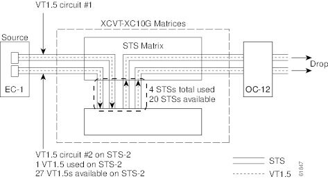
The XCVT and XC10G perform VT1.5 multiplexing through 24 logical STS ports on the XCVT or XC10G VT matrix. Each logical STS port can carry 28 VT1.5s. Subsequently, the VT matrix has capacity for 672 VT1.5s terminations, or 336 VT1.5 circuits, since every circuit requires two terminations, one for ingress and one for egress. However, this capacity is only achievable if:

Every STS port on the VT matrix carries 28 VT1.5s.

The node is in a BLSR.

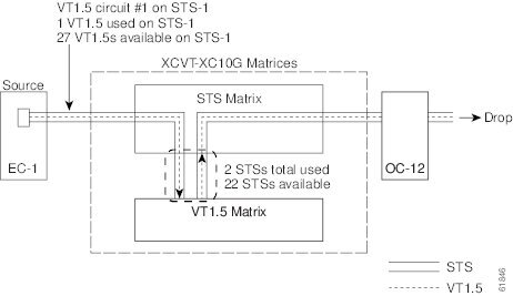
For example, if you create a VT1.5 circuit from STS-1 on a drop card and a second VT1.5 circuit from STS-2, two VT matrix STS ports will be used, as shown in Figure 9-9. If you create a second VT1.5 circuit from the same STS port on the drop card, no additional logical STS ports are used on the VT matrix. However, if the next VT1.5 circuit originates on a different STS, a second STS port on the VT matrix is used, as shown in Figure 9-10. If you continued to create VT1.5 circuits on a different EC-1 STSs, the VT matrix capacity would be reached after you created 12 VT1.5 circuits.

Figure 9-9 VT Matrix Example: One VT1.5 Circuit on One STS

Figure 9-10 Example #2: Two VT1.5 Circuits in a BLSR


Note Circuits with DS1-14 and DS1N-14 circuit sources or destinations use one STS port on the VT matrix. Because you can only create 14 VT1.5 circuits from the DS-1 cards, 14 VT1.4s will be unused on the VT matrix.


VT matrix capacity is also affected by SONET protection topology and node position within the circuit path. Matrix usage is slightly higher for path protection configuration, and 1+1 nodes than at BLSR nodes. Circuit use two VT matrix ports at pass-through nodes if VT tunnels and aggregation points are not used. If the circuit is routed on a VT tunnel or an aggregation point, no VT matrix resources are used. Table 9-6 shows basic STS port usage rates.

Table 9-6 VT Matrix Port Usage for One VT1.5 Circuit

Node Type
No Protection
BLSR
Path Protection Configuration
1+1

Circuit source or destination node

2

2

3

3

Circuit pass-through node without VT Tunnel

2

2

2

2

Circuit pass-through node with VT Tunnel

0

0

0

0


Cross-connect card resources can be viewed on the Maintenance > Cross-Connect > Resource Usage tabs. This tab shows:

STS-1 Matrix—The percent of STS matrix resources that are used. 288 STSs are available on XC and XCVT cards; 1152 are available on XC10G cards.

VT Matrix Ports—The percent of the VT matrix ports (logical STS ports) that are used. No ports are available on XC cards; 24 are available on XCVT and XC10G cards. The VT Port Matrix Detail shows the percent of each VT matrix port that is used.

VT Matrix—The percent of the total VT matrix terminations that are used. 672 terminations are available, which is the number of logical STS VT matrix ports (24) multiplied by the number of VT1.5s per port (28).

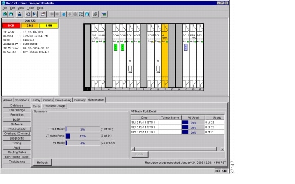
Figure 9-11 shows an example of a cross-connect card resource usage on a path protection configuration node. One STS circuit and eight VT1.5 circuits originate at the node. The VT1.5 circuits all originate on the same STS port.

Figure 9-11 Viewing Cross-Connect Card Resource Usage

In the example, cross-connect resource usage is shown as follows:

STS-1 Matrix—Six STS-1 matrix ports are used, three for the STS circuit and three for the eight VT1.5 circuits, which originate on the same STS.

VT Matrix Ports—Three VT matrix ports are used because all VT1.5 circuits originate on the same STS port: one for the I/O card and one port for each path protection configuration trunk card.

VT Matrix—24 VT matrix terminations are used; eight for the I/O card and eight for each path protection configuration trunk card. The VT Matrix Port Detail shows the VT matrix ports and matrix terminations usage.

To maximize resources on the cross-connect card VT matrix, keep the following points in mind as you provision circuits:

When creating VT1.5 circuits, use all 28 VT1.5s on a given port or STS before moving to the next port or STS.

Try to use EC-1 DS3XM or OC-N cards as the VT1.5 circuit source and destination. VT1.5 circuits with DS-1-14 or DS1N-14 sources or destinations use a full port on the VT matrix even though only 14 VT1.5 circuits can be created.

Use VT tunnels and VT aggregation points to reduce VT matrix utilization. VT tunnels allow VT1.5 circuits to bypass the VT matrix on pass-through nodes. They are cross-connected as an STS and only go through the STS matrix. VT aggregation points allow multiple VT1.5 circuits to be aggregated onto a single STS to bypass the VT matrix at the aggregation node.

9.3 DCC Tunnels

SONET provides four data communications channels (DCCs) for network element operations, administration, maintenance, and provisioning: one on the SONET Section layer (DCC1) and three on the SONET Line layer (DCC2, DCC3, DCC4). The ONS 15454 uses the Section DCC for ONS 15454 management and provisioning.

You can use the three Line DCCs and the Section DCC (when not used for ONS 15454 DCC terminations) to tunnel third-party SONET equipment across ONS 15454 networks. A DCC tunnel end-point is defined by Slot, Port, and DCC, where DCC can be either the Section DCC or one of the Line DCCs. You can link a Section DCC to an Line DCC, and a Line DCC to a Section DCC. You can also link Line DCCs to Line DCCs and link Section DCCs to Section DCCs. To create a DCC tunnel, you connect the tunnel endpoints from one ONS 15454 optical port to another.

Each ONS 15454 can support up to 32 DCC tunnel connections. Table 9-7 shows the DCC tunnels that you can create.

Table 9-7 DCC Tunnels

DCC
SONET
Layer
SONET
Bytes
OC-3
(All Ports)
OC-12, OC-48, OC-192

DCC1

Section

D1 - D3

Yes

Yes

DCC2

Line

D4 - D6

No

Yes

DCC3

Line

D7 - D9

No

Yes

DCC4

Line

D10 - D12

No

Yes


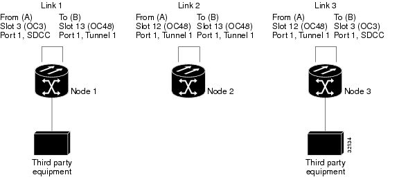
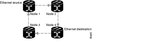
Figure 9-12 shows a DCC tunnel example. Third-party equipment is connected to OC-3 cards at Node 1/Slot 3/Port 1 and Node 3/Slot 3/Port 1. Each ONS 15454 node is connected by OC-48 trunk cards. In the example, three tunnel connections are created, one at Node 1 (OC-3 to OC-48), one at Node 2 (OC-48 to OC-48), and one at Node 3 (OC-48 to OC-3).

Figure 9-12 DCC Tunnel

When you create DCC tunnels, keep the following guidelines in mind:

Each ONS 15454 can have up to 32 DCC tunnel connections.

Each ONS 15454 can have up to 10 Section DCC terminations.

A Section DCC that is terminated cannot be used as a DCC tunnel endpoint.

A Section DCC that is used as an DCC tunnel endpoint cannot be terminated.

All DCC tunnel connections are bidirectional.

9.4 Multiple Drops for Unidirectional Circuits

Unidirectional circuits can have multiple drops for use in broadcast circuit schemes. In broadcast scenarios, one source transmits traffic to multiple destinations, but traffic is not returned to the source.

When you create a unidirectional circuit, the card that does not have its backplane receive (Rx) input terminated with a valid input signal generates a loss of service (LOS) alarm. To mask the alarm, create an alarm profile suppressing the LOS alarm and apply the profile to the port that does not have its Rx input terminated.

9.5 Monitor Circuits

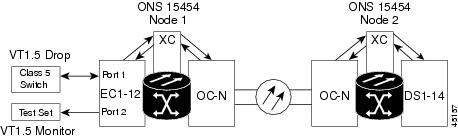
Monitor circuits are secondary circuits that monitor traffic on primary bidirectional circuits. Figure 9-13 shows an example of a monitor circuit. At Node 1, a VT1.5 is dropped from Port 1 of an EC1-12 card. To monitor the VT1.5 traffic, plug test equipment into Port 2 of the EC1-12 card and provision a monitor circuit to Port 2. Circuit monitors are one-way. The monitor circuit in Figure 9-13 monitors VT1.5 traffic received by Port 1 of the EC1-12 card.

Figure 9-13 VT1.5 Monitor Circuit Received at an EC1-12 Port


Note Monitor circuits cannot be used with EtherSwitch circuits.


9.6 Path Protection Configuration Circuits

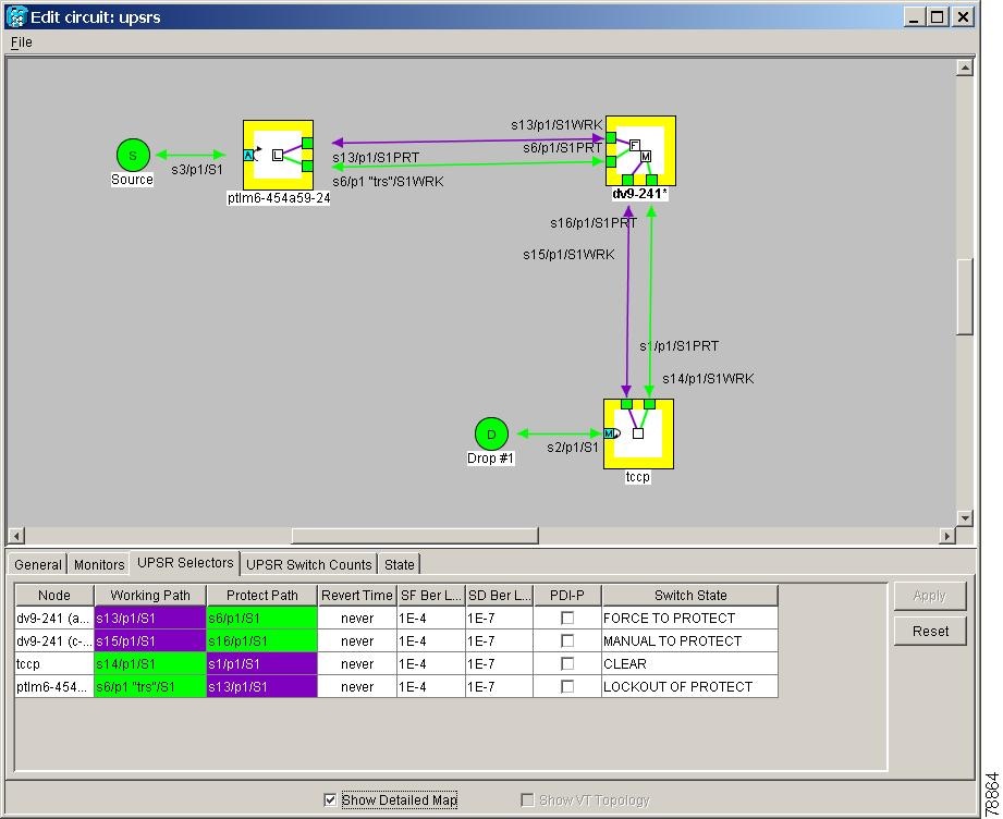
Use the Edit Circuits window to change path protection configuration selectors and switch protection paths (Figure 9-14). In this window, you can:

View the path protection configuration circuit's working and protection paths

Edit the reversion time

Edit the Signal Fail/Signal Degrade thresholds

Change PDI-P settings

Perform maintenance switches on the circuit selector

View switch counts for the selectors

Figure 9-14 Editing Path Protection Configuration Selectors

9.7 BLSR Protection Channel Circuits

You can provision circuits to carry traffic on BLSR protection channels when conditions are fault-free. Traffic routed on BLSR protection channels, called extra traffic, has lower priority than the traffic on the working channels and has no means for protection. During ring or span switches, protection channel circuits are preempted and squelched. For example, in a 2-fiber OC-48 BLSR, STSs 25-48 can carry extra traffic when no ring switches are active, but protection channel circuits on these STSs are preempted when a ring switch occurs. When the conditions that caused the ring switch are remedied and the ring switch is removed, protection channel circuits are restored if the BLSR is provisioned as revertive.

Provisioning traffic on BLSR protection channels is performed during circuit provisioning. The protection channel check box appears whenever Fully Protected Path is deselected on the circuit creation wizard. Refer to the Cisco ONS 15454 Procedure Guide for more information. When provisioning protection channel circuits, two considerations are important to keep in mind:

If BLSRs are provisioned as nonrevertive, protection channel circuits will not be restored automatically after a ring or span switch. You must switch the BLSR manually.

Protection channel circuits will be routed on working channels when you upgrade a BLSR from a 2-fiber to a 4-fiber or from one optical speed to a higher optical speed. For example, if you upgrade a 2-fiber OC-48 BLSR to an OC-192, STSs 25-48 on the OC-48 BLSR become working channels on the OC-192 BLSR.

9.8 Path Trace

The SONET J1 Path Trace is a repeated, fixed-length string comprised of 64 consecutive J1 bytes. You can use the string to monitor interruptions or changes to circuit traffic. Table 9-8 shows the ONS 15454 cards that support path trace. DS-1 and DS-3 cards can transmit and receive the J1 field, while the EC-1, OC-3, OC-48AS, and OC-192 can only receive the J1 bytes. Cards not listed in the table do not support the J1 byte.

Table 9-8 ONS 15454 Cards Capable of Path Trace

J1 Function
Cards

Transmit and Receive

DS1-14, DS1N-14

DS3-12E, DS3N-12E, DS3XM-6

G1000-4

Receive Only

EC1-12

OC3 IR 4 1310

OC12/STM4-4

OC48 IR/STM16 SH AS 1310, OC48 LR/STM16 LH AS 1550

OC192 LR/STM64 LH 1550


The J1 path trace transmits a repeated, fixed-length string. If the string received at a circuit drop port does not match the string the port expects to receive, an alarm is raised. Two path trace modes are available:

Automatic—The receiving port assumes that the first J1 string it receives is the baseline J1 string.

Manual—The receiving port uses a string that you manually enter as the baseline J1 string.

9.9 Path Signal Label, C2 Byte

One of the overhead bytes in the SONET frame is the C2 Byte. The SONET standard defines the C2 byte as the path signal label. The purpose of this byte is to communicate the payload type being encapsulated by the SONET framing overhead (FOH). The C2 byte functions similarly to EtherType and Logical Link Control (LLC)/Subnetwork Access Protocol (SNAP) header fields on an Ethernet network; it allows a single interface to transport multiple payload types simultaneously. C2 byte hex values are provided in Table 9-9.

Table 9-9 STS Path Signal Label Assignments for Signals 

Hex Code
Content of the STS SPE

0x00

Unequipped

0x01

Equipped - non specific payload

0x02

Virtual Tributary (VT) structured STS-1 (DS1)

0x03

Locked VT mode

0x04

Asynchronous mapping for DS3

0x12

Asynchronous mapping for DS4NA

0x13

Mapping for ATM

0x14

Mapping for DQDB

0x15

Asynchronous mapping for FDDI

0x16

HDLC-Over-SONET Mapping

0xFD

Reserved

0xFE

0.181 Test Signal (TSS1 to TSS3) Mapping SDH Network

0xFF

AIS-P


If a circuit is provisioned using a terminating card, the terminating card provides the C2 byte. A VT circuit is terminated at the XCVT and the XCVT generates the C2 byte (0x02) downstream to the STS terminating cards. XCVT generates the C2 value (0x02) to the DS1 or DS3XM terminating card. If an optical circuit is created with no terminating cards, the test equipment must supply the path overhead in terminating mode. If the test equipment is in "path through mode," the C2 values usually change rapidly between 0x00 and 0xFF. Adding a terminating card to an optical circuit usually fixes a circuit having C2 byte problems. Table 9-10 lists signals with payload defects.

Table 9-10 STS Path Signal Label Assignments for Signals with Payload Defects 

Hex Code
Content of the STS SPE

0xE1

VT-structured STS-1 SPE with 1 VTx Payload Defect (STS-1 with 1 VTx PD)

0xE2

STS-1 with 2 VTx PDs

0xE3

STS-1 with 3 VTx PDs

0xE4

STS-1 with 4 VTx PDs

0xE5

STS-1 with 5 VTx PDs

0xE6

STS-1 with 6 VTx PDs

0xE7

STS-1 with 7 VTx PDs

0xE8

STS-1 with 8 VTx PDs

0xE9

STS-1 with 9 VTx PDs

0xEA

STS-1 with 10 VTx PDs

0xEB

STS-1 with 11 VTx PDs

0xEC

STS-1 with 12 VTx PDs

0xED

STS-1 with 13 VTx PDs

0xEE

STS-1 with 14 VTx PDs

0xEF

STS-1 with 15 VTx PDs

0xF0

STS-1 with 16 VTx PDs

0xF1

STS-1 with 17 VTx PDs

0xF2

STS-1 with 18 VTx PDs

0xF3

STS-1 with 19 VTx PDs

0xF4

STS-1 with 20 VTx PDs

0xF5

STS-1 with 21 VTx PDs

0xF6

STS-1 with 22 VTx PDs

0xF7

STS-1 with 23 VTx PDs

0xF8

STS-1 with 24 VTx PDs

0xF9

STS-1 with 25 VTx PDs

0xFA

STS-1 with 26 VTx PDs

0xFB

STS-1 with 27 VTx PDs

0xFC

VT-structured STS-1 SPE with 28 VT1.5

Payload defects or a non-VT-structured STS-1 or STS-Nc SPE with a payload defect.

0xFF

Reserved


9.10 Automatic Circuit Routing

If you select automatic routing during circuit creation, CTC routes the circuit by dividing the entire circuit route into segments based on protection domains. For unprotected segments of circuits provisioned as fully protected, CTC finds an alternate route to protect the segment, creating a virtual path protection configuration. Each segment of a circuit path is a separate protection domain. Each protection domain is protected in a specific protection scheme including card protection (1+1, 1:1, etc.) or SONET topology (path protection configuration, BLSR, etc.).

The following list provides principles and characteristics of automatic circuit routing:

Circuit routing tries to use the shortest path within the user-specified or network-specified constraints. VT tunnels are preferable for VT circuits because VT tunnels are considered shortcuts when CTC calculates a circuit path in path-protected mesh networks.

If you do not choose fully path protected during circuit creation, circuits can still contain protected segments. Because circuit routing always selects the shortest path, one or more links and/or segments can have some protection. CTC does not look at link protection while computing a path for unprotected circuits.

Circuit routing will not use links that are down. If you want all links to be considered for routing, do not create circuits when a link is down.

Circuit routing computes the shortest path when you add a new drop to an existing circuit. It tries to find the shortest path from the new drop to any nodes on the existing circuit.

If the network has a mixture of VT-capable nodes and VT-incapable nodes, CTC may automatically create a VT tunnel. Otherwise, CTC asks you whether a VT tunnel is needed.

9.10.1 Bandwidth Allocation and Routing

Within a given network, CTC will route circuits on the shortest possible path between source and destination based on the circuit attributes, such as protection and type. CTC will consider using a link for the circuit only if the link meets the following requirements:

The link has sufficient bandwidth to support the circuit.

The link does not change the protection characteristics of the path.

The link has the required time slots to enforce the same time slot restrictions for BLSR.

If CTC cannot find a link that meets these requirements, an error is displayed.

The same logic applies to VT circuits on VT tunnels. Circuit routing typically favors VT tunnels because VT tunnels are shortcuts between a given source and destination. If the VT tunnel in the route is full (no more bandwidth), CTC asks whether you want to create an additional VT tunnel.

9.10.2 Secondary Sources and Drops

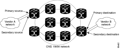
CTC supports secondary sources and drops. Secondary sources and drops typically interconnect two "foreign" networks, as shown in Figure 9-15. Traffic is protected while it goes through a network of ONS 15454s.

Figure 9-15 Secondary Sources and Drops

Several rules apply to secondary sources and drops:

CTC does not allow a secondary destination for unidirectional circuits because you can always specify additional destinations (drops) after you create the circuit.

Primary and secondary sources should be on the same node.

Primary and secondary destinations should be on the same node.

The sources and drops cannot be DS-3, DS3XM, or DS-1-based STS-1s or VT1.5s.

Secondary sources and destinations are permitted only for regular STS/VT1.5 connections (not for VT tunnels and Multicard EtherSwitch circuits).

For point-to-point (straight) Ethernet circuits, only SONET STS endpoints can be specified as multiple sources or drops.

For bidirectional circuits, CTC creates a path protection configuration connection at the source node that allows traffic to be selected from one of the two sources on the ONS 15454 network. If you check the Fully Path Protected option during circuit creation, traffic is protected within the ONS 15454 network. At the destination, another path protection configuration connection is created to bridge traffic from the ONS 15454 network to the two destinations. A similar but opposite path exists for the reverse traffic flowing from the destinations to the sources.

For unidirectional circuits, a path protection configuration drop-and-continue connection is created at the source node.

9.11 Manual Circuit Routing

Routing circuits manually allows you to:

Choose a specific path, not necessarily the shortest path.

Choose a specific STS/VT1.5 on each link along the route.

Create a shared packet ring for multicard EtherSwitch circuits.

Choose a protected path for multicard EtherSwitch circuits, allowing virtual path protection configuration segments

CTC imposes the following rules on manual routes:

All circuits, except multicard EtherSwitch circuits in a shared packet ring, should have links with a direction that flows from source to destination. This is true for multicard EtherSwitch circuits that are not in a shared packet ring.

If you enabled fully path protected, choose a diverse protect (alternate) path for every unprotected segment (Figure 9-16).

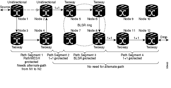
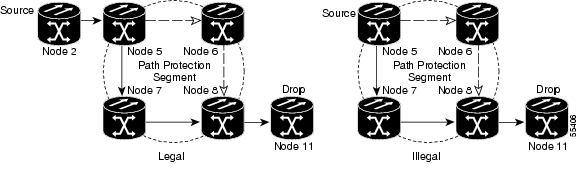
Figure 9-16 Alternate Paths for Virtual Path Protection Configuration Segments

For multicard EtherSwitch circuits, the fully path protected option is ignored.

For a node that has a path protection configuration selector based on the links chosen, the input links to the path protection configuration selectors cannot be 1+1 or BLSR protected (see Figure 9-17). The same rule applies at the path protection configuration bridge.

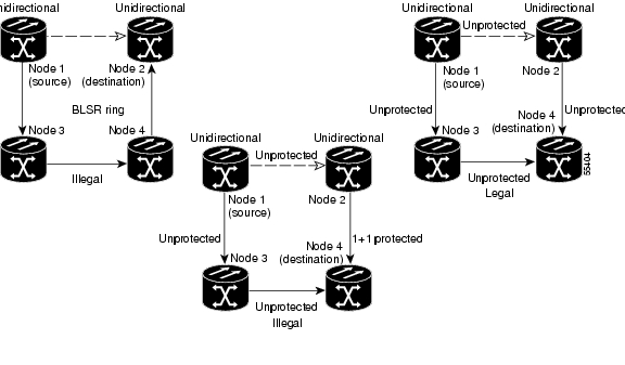
Figure 9-17 Mixing 1+1 or BLSR Protected Links With a Path Protection Configuration

Choose the links of multicard EtherSwitch circuits in a shared packet ring to route from source to destination back to source (see Figure 9-18). Otherwise, a route (set of links) chosen with loops is invalid.

Figure 9-18 Ethernet Shared Packet Ring Routing

Multicard EtherSwitch circuits can have virtual path protection configuration segments if the source or destination is not in the path protection configuration domain. This restriction also applies after circuit creation; therefore, if you create a circuit with path protection configuration segments, Ethernet drops cannot exist anywhere on the path protection configuration segment (see Figure 9-19).

Figure 9-19 Ethernet and Path Protection Configuration

VT tunnels cannot be the endpoint of a path protection configuration segment. A path protection configuration segment endpoint is where the path protection configuration selector resides.

If you provision full path protection, CTC verifies that the route selection is protected at all segments. A route can have multiple protection domains with each domain protected by a different scheme.

Table 9-11 through Table 9-14 summarize the available node connections. Any other combination is invalid and will generate an error.

Table 9-11 Bidirectional STS/VT/Regular Multicard EtherSwitch/Point-to-Point (Straight) Ethernet Circuits 

# of Inbound Links
# of Outbound Links
# of Sources
# of Drops
Connection Type

2

1

path protection configuration

2

1

path protection configuration

2

1

path protection configuration

1

2

path protection configuration

1

2

path protection configuration

1

2

path protection configuration

2

2

Double path protection configuration

2

2

Double path protection configuration

2

2

Double path protection configuration

1

1

Two way

0 or 1

0 or 1

Ethernet node source

Ethernet

0 or 1

0 or 1

Ethernet node drop

Ethernet


Table 9-12 Unidirectional STS/VT Circuit 

# of Inbound Links
# of Outbound Links
# of Sources
# of Drops
Connection Type

1

1

One way

1

2

path protection configuration head end

2

1

path protection configuration head end

2

1+

path protection configuration drop and continue


Table 9-13 Multicard Group Ethernet Shared Packet Ring Circuit

# of Inbound Links
# of Outbound Links
# of Sources
# of Drops
Connection Type
At intermediate nodes only

2

1

path protection configuration

1

2

path protection configuration

2

2

Double path protection configuration

1

1

Two way

At source or destination nodes only

1

1

Ethernet


Table 9-14 Bidirectional VT Tunnels 

# of Inbound Links
# of Outbound Links
# of Sources
# of Drops
Connection Type
At intermediate nodes only

2

1

path protection configuration

1

2

path protection configuration

2

2

Double path protection configuration

1

1

Two way

At source nodes only

1

VT tunnel endpoint

At destination nodes only

1

-

-

-

VT tunnel endpoint


Although virtual path protection configuration segments are possible in VT tunnels, VT tunnels are still considered unprotected. If you need to protect VT circuits use two independent VT tunnels that are diversely routed or use a VT tunnel that is routed over 1+1, BLSR, or a mixture of 1+1 and BLSR links.

9.12 Constraint-Based Circuit Routing

When you create circuits, you can choose fully protected path to protect the circuit from source to destination. The protection mechanism used depends on the path CTC calculates for the circuit. If the network is composed entirely of BLSR and/or 1+1 links, or the path between source and destination can be entirely protected using 1+1 and/or BLSR links, no path-protected mesh network (PPMN), or virtual path protection configuration, protection is used.

If PPMN protection is needed to protect the path, set the level of node diversity for the PPMN portions of the complete path on the Circuit Creation dialog box:

Required—Ensures that the primary and alternate paths of each PPMN domain in the complete path have a diverse set of nodes.

Desired—CTC looks for a node diverse path; if a node diverse path is not available, CTC finds a link diverse path for each PPMN domain in the complete path.

Don't Care—Creates only a link diverse path for each PPMN domain.

When you choose automatic circuit routing during circuit creation, you have the option to require and/or exclude nodes and links in the calculated route. You can use this option to:

Simplify manual routing, especially if the network is large and selecting every span is tedious. You can select a general route from source to destination and allow CTC to fill in the route details.

Balance network traffic; by default CTC chooses the shortest path, which can load traffic on certain links while other links have most of their bandwidth available. By selecting a required node and/or a link, you force the CTC to use (or not use) an element, resulting in more efficient use of network resources.

CTC considers required nodes and links to be an ordered set of elements. CTC treats the source nodes of every required link as required nodes. When CTC calculates the path, it makes sure the computed path traverses the required set of nodes and links and does not traverse excluded nodes and links.

The required nodes and links constraint is only used during the primary path computation and only for PPMN domains/segments. The alternate path is computed normally; CTC uses excluded nodes/links when finding all primary and alternate paths on PPMNs.


[an error occurred while processing this directive]