Downloads |
 Feedback Feedback
|
Table Of Contents
Cisco 10005 Extender Card Information
Installing or Replacing Extender Cards
Cisco 10005 Extender Card Information
All Cisco 10005 line cards connect to a backplane in the center of the chassis, and require extender cards to deliver the alarm, BITS clock, and DS3 signals to the rear of the chassis to make them accessible. The Cisco 10005 alarm extender card and T3/E3 extender card extend and terminate these signals.
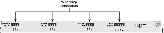
The alarm extender card slides into the bottom slot in the back of the chassis, and terminates the alarm signals with wire wrap header connectors (Figure A-1).
Figure A-1 Alarm Extender Card
The T3/E3 extender card extends the signals of the channelized T3 line card located in the slot directly opposite in the front of the chassis, and terminates the eight pairs of DS3 signals with BNC connectors (Figure A-2)
Figure A-2 T3/E3 Extender Card
.Installation Guidelines
Before you perform the procedures in this guide, we recommend that you read Chapter 16, "Preparing for Installation."
The Cisco 10005 system is hot-swappable, which means you can remove and replace line cards while the system is operating.
Be sure to remove the correct extender card. If you remove the alarm extender card, this disconnects the BITS clock and external alarm devices. If you remove the T3/E3 extender card, this stops all traffic to and from its associated CT3 line card.
CautionTo prevent electrostatic discharge (ESD) damage, handle extender cards by the faceplate or the card carrier edges only. Avoid touching the extender card printed circuit board, components, or any connector pins.
Required Tools and Equipment
The following tools and equipment are required to install an extender card:
•
•
Installing or Replacing Extender Cards
This section describes how to install or replace an extender card in the Cisco 10005 chassis, and contains the following procedures:
Installing an Extender Card
You can only install the alarm extender card in the lowest slot in the rear of the Cisco 10005 chassis.
The T3/E3 extender card extends the DS3 signals of the channelized T3 line card, located in the slot directly opposite in the front of the chassis. For example, a T3/E3 extender card installed in the highest slot in the rear of the chassis extends the signals of the channelized T3 line card that is installed in the highest slot in the front of the chassis.
Use the following procedure to install an extender card into the rear of the Cisco 10005 chassis:
Note
Step 1
Step 2
Step 3
Step 4
Removing an Extender Card
Ensure that all wires or cables are disconnected from the extender card, and then use the following procedure to remove an extender card from the chassis:
Step 1
Step 2
Step 3
Step 4
Step 5
Warning
Troubleshooting
Table 1 provides tips for troubleshooting the extender cards.