Feedback
Table Of Contents
Removing and Replacing the Chassis Cover
Removing and Replacing the IDE Hard-Disk Drive
Removing and Replacing the Compact Flash Device
Removing the Compact Flash Device
Replacing the Compact Flash Device
Removing and Installing the 4FE Card
Installing IDS-4215
This chapter describes IDS-4215 and how to install it. It also describes the accessories and how to install them. It contains the following sections:
•
Front and Back Panel Features
•
•
•
•
•
WarningIntroducing IDS-4215
IDS-4215 can monitor up to 80 Mbps of aggregate traffic and is suitable for T1/E1 and T3 environments. With the addition of the four-port fast Ethernet (4FE) card, IDS-4215 supports five sensing interfaces (10/100BASE-TX), which provide simultaneous protection for multiple subnets.
Note
The sensing interfaces and the command and control interface are all 10/100BASE-TX.
Front and Back Panel Features
This section describes the IDS-4215 front and back panel features and indicators.
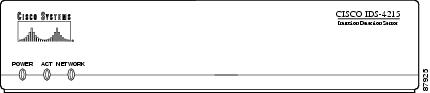
Figure 3-1 shows the front view of IDS-4215.
Figure 3-1 IDS-4215 Front Panel Features
Table 3-1 describes the front panel indicators on IDS-4215.
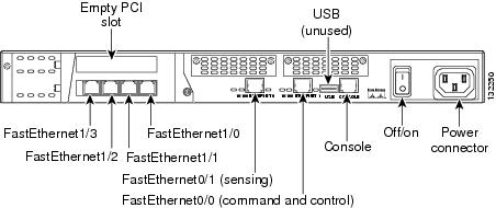
Figure 3-2 shows the back view of IDS-4215.
Figure 3-2 IDS-4215 Back Panel Features
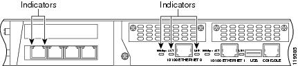
WarningThe built-in Ethernet ports have three indicators per port and the 4FE card has two indicators per port. Figure 3-3 shows the back panel indicators.
Figure 3-3 IDS-4215
Table 3-2 lists the back panel indicators.
Specifications
Table 3-3 lists the specifications for IDS-4215.
Note
Accessories
WarningIDS-4215 accessories kit contains the following:
•
•
•
•
•
•
Surface Mounting
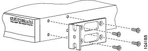
If you are not rack mounting IDS-4215, you must attach the rubber feet to the bottom of IDS-4215 as shown in Figure 3-4. The rubber feet are shipped in the accessories kit.
Figure 3-4 Surface Mounting IDS-4215
Caution
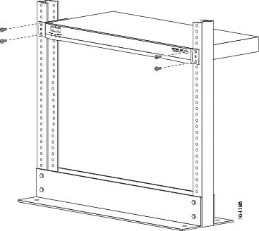
Rack Mounting
If you are installing the 4FE card in IDS-4215, do not install the mounting brackets until after you have installed the 4FE card.
Note
To rack mount IDS-4215, follow these steps:
Step 1
You can attach the brackets to the holes near the front of IDS-4215.
Step 2
.
Installing IDS-4215
Warning
Caution
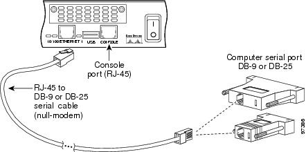
To install IDS-4215 on the network, follow these steps:
Step 1
Step 2
Step 3
Note
Note
Step 4
Step 5
IDS-4215 has the following interfaces:
•
•
•
Step 6
Make sure the BIOS version is 5.1.7 and the ROMMON version is 1.4 before upgrading IDS-4215 to 5.0. For the procedure, see Upgrading the BIOS and ROMMON.
Note
Step 7
For the procedure, see Initializing the Sensor.
Step 8
For the procedure, see Obtaining Cisco IPS Software.
You are now ready to configure intrusion prevention on IDS-4215.
For More Information
•
•
–
–
Upgrading the BIOS and ROMMON
Some TFTP servers limit the maximum file size that can be transferred to ~32 MB. Therefore, we recommend the following TFTP servers:
•
Tftpd32 version 2.0, available at:
•
Tftp-hpa series, available at:
http://www.kernel.org/pub/software/network/tftp/
The BIOS/ROMMON upgrade utility (IDS-4215-bios-5.1.7-rom-1.4.bin) upgrades the BIOS of IDS-4215 to version 5.1.7 and the ROMMON to version 1.4.
To upgrade the BIOS and ROMMON on IDS-4215, follow these steps:
Step 1
For the procedure for locating software on Cisco.com, see Obtaining Cisco IPS Software.
Note
Step 2
While rebooting, IDS-4215 runs the BIOS POST. After the completion of POST, the console displays the message:
Evaluating Run Options ...for about 5 seconds.Step 3
The console display resembles the following:
CISCO SYSTEMS IDS-4215Embedded BIOS Version 5.1.3 05/12/03 10:18:14.84Compiled by ciscouserEvaluating Run Options ...Cisco ROMMON (1.2) #0: Mon May 12 10:21:46 MDT 2003Platform IDS-42150: i8255X @ PCI(bus:0 dev:13 irq:11)1: i8255X @ PCI(bus:0 dev:14 irq:11)Using 1: i82557 @ PCI(bus:0 dev:14 irq:11), MAC: 0000.c0ff.ee01Use ? for help.rommon>Step 4
rommon> interface port_numberThe port in use is listed just before the rommon prompt. Port 1 (default port) is being used as indicated by the text,
Using 1: i82557 @ PCI(bus:0 dev:14 irq:11), MAC: 0000.c0ff.ee01.
Note
Step 5
rommon> address ip_address
Note
Step 6
rommon> server ip_addressStep 7
rommon> gateway ip_addressStep 8
rommon> ping server_ip_addressrommon> ping serverStep 9
rommon> file filenameExample:
rommon> file IDS-4215-bios-5.1.7-rom-1.4.bin
Note
Step 10
rommon> tftpStep 11
IDS-4215 reboots when the update is complete.
Caution
Removing and Replacing the Chassis Cover
Warning
Caution
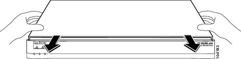
This section describes how to remove and replace the IDS-4215 chassis cover. It contains the following topics:
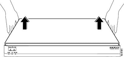
Removing the Chassis Cover
Note
To remove the chassis cover, follow these steps:
Step 1
Step 2
sensor# reset powerdownWait for the power down message before continuing with Step 3.
Note
Step 3
Step 4
Step 5
For more information, see Working in an ESD Environment.
Step 6
Step 7
Step 8
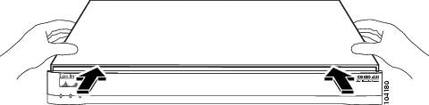
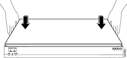
Replacing the Chassis Cover
Caution
To replace the chassis cover, follow these steps:
Step 1
Step 2
Step 3
Step 4
Step 5
Step 6
If you are reinstalling IDS-4215 in a rack, see Rack Mounting.
Step 7
For the procedure, see Installing IDS-4215.
Removing and Replacing the IDE Hard-Disk Drive
Warning
Caution
Caution
This section describes how to remove and replace the IDE hard-disk drive. It contains the following topics:
•
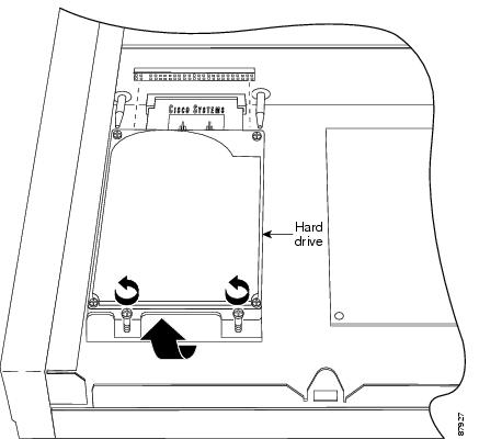
Removing the Hard-Disk Drive
To remove the hard-disk drive from IDS-4215, follow these steps:
Step 1
Step 2
sensor# reset powerdownWait for the power down message before continuing with Step 3.
Note
Step 3
Step 4
Step 5
For more information, see Working in an ESD Environment.
Step 6
For the procedure, see Removing the Chassis Cover.
Step 7
Step 8
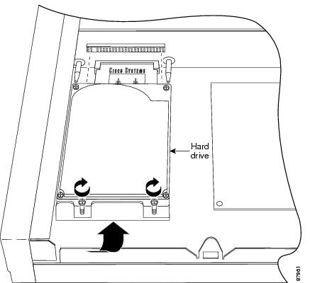
Replacing the Hard-Disk Drive
To replace the hard-disk drive in IDS-4215, follow these steps:
Step 1
For more information, see Working in an ESD Environment.
Step 2
Step 3
Step 4
Step 5
For the procedure, see Replacing the Chassis Cover.
Removing and Replacing the Compact Flash Device
Warning
Caution
This section describes how to remove and replace the compact flash device in IDS-4215. It contains the following topics:
•
•
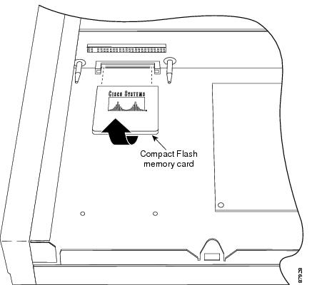
Removing the Compact Flash Device
To remove the compact flash device from IDS-4215, follow these steps:
Step 1
Step 2
sensor# reset powerdownWait for the power down message before continuing with Step 3.
Note
Step 3
Step 4
Step 5
For more information, see Working in an ESD Environment.
Step 6
For the procedure, see Removing the Chassis Cover.
Step 7
For the procedure, see Removing the Hard-Disk Drive.
Step 8
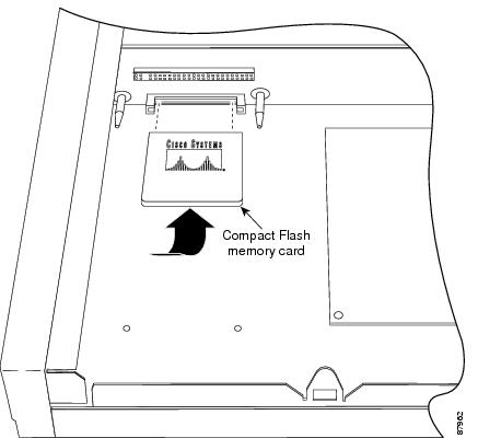
Replacing the Compact Flash Device
To replace the compact flash device in IDS-4215, follow these steps:
Step 1
For more information, see Working in an ESD Environment.
Step 2
Step 3
Step 4
For the procedure, see Replacing the Hard-Disk Drive.
Step 5
For the procedure, see Replacing the Chassis Cover.
Removing and Installing the 4FE Card
Warning
Caution
You can order IDS-4215 with the 4FE card already installed or you can upgrade IDS-4215 with the 4FE card to have four additional interfaces. This section describes how to remove and install the 4FE card, and contains the following topics:
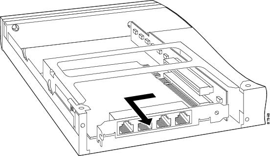
Removing the 4FE Card
To remove the 4FE card, follow these steps:
Step 1
Step 2
sensor# reset powerdownWait for the power down message before continuing with Step 3.
Note
Step 3
Step 4
Step 5
For more information, see Working in an ESD Environment.
Step 6
For the procedure, see Removing the Chassis Cover.
Step 7
Step 8
Step 9
Step 10
Step 11
Step 12
For the procedure, see Replacing the Chassis Cover.
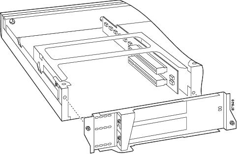
Installing the 4FE Card
We recommend that you install the 4FE card in the bottom slot. We do not support installation of the 4FE card in the top slot.
Note
To install a 4FE card in IDS-4215, follow these steps:
Step 1
sensor# reset powerdownWait for the power down message before continuing with Step 2.
Step 2
Step 3
Step 4
For more information, see Working in an ESD Environment.
Step 5
For the procedure, see Removing the Chassis Cover.
Step 6
Step 7
Note
Step 8
Step 9
Step 10
Step 11
For the procedure, see Replacing the Chassis Cover.
You will need to assign the new interfaces (FastEthernet1/0, FastEthernet1/1, FastEthernet1/2, and FastEthernet1/3). For the CLI procedure, refer to Configuring Interfaces. For the IDM procedure, refer to Configuring Interfaces.