Installing IPS-4240 and IPS-4255

Table Of Contents

Installing IPS-4240 and IPS-4255

Introducing IPS-4240 and IPS-4255

Front and Back Panel Features

Specifications

Accessories

Rack Mounting

Installing IPS-4240 and IPS-4255


Installing IPS-4240 and IPS-4255


This chapter describes IPS-4240 and IPS-4255 and how to install them. It also describes the accessories and how to install them. This chapter contains the following sections:

Introducing IPS-4240 and IPS-4255

Front and Back Panel Features

Specifications

Accessories

Rack Mounting

Installing IPS-4240 and IPS-4255

Introducing IPS-4240 and IPS-4255

IPS-4240 and IPS-4255 deliver high port density in a small form factor. They use a compact flash device for storage rather than the hard-disk drives used in other sensor models.

IPS-4240 monitors up to 250 Mbps of aggregate network traffic on multiple sensing interfaces and is inline ready. It replaces IDS-4235. There are four 10/100/1000 copper sensing interfaces.


Note The 250-Mbps performance for IPS-4240 is based on the following conditions: 2500 new TCP connections per second, 2500 HTTP transactions per second, average packet size of 445 bytes, and the system running Cisco IPS 5.0 software. The 250-Mbps performance is traffic combined from all four sensing interfaces.


IPS-4255 monitors up to 600 Mbps of aggregate network traffic on multiple sensing interfaces and is also inline ready. It replaces IDS-4250-TX. There are four 10/100/1000 copper sensing interfaces.


Note IDS-4250-SX and the IDS-4250-XL are not being replaced by IPS-4255 at this time.


Note The 600-Mbps performance for IPS-4255 is based on the following conditions: 6000 new TCP connections per second, 6000 HTTP transactions per second, average packet size of 445 bytes, and the system running Cisco IPS 5.0 software. The 600-Mbps performance is traffic combined from all four sensing interfaces.


Note IPS-4240 and the IPS-4255 do not support redundant power supplies.


Front and Back Panel Features

This section describes the IPS-4240 and IPS-4255 front and back panel features and indicators.


Note Although the graphics show IPS-4240, the IPS-4255 has the same front and back panel features and indicators.


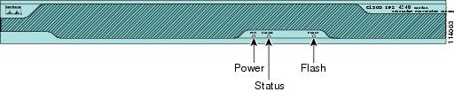
Figure 5-1 shows the front view of IPS-4240 and IPS-4255.

Figure 5-1 IPS-4240/IPS-4255 Front Panel Features

Table 5-1 describes the front panel indicators on IPS-4240 and IPS-4255.

Table 5-1 Front Panel Indicators 

Indicator
Description

Power

Off indicates no power. Green when the power supply is running.

Status

Blinks green while the power-up diagnostics are running or the system is booting. Solid green when the system has passed power-up diagnostics. Solid amber when the power-up diagnostics have failed.

Flash

Off when the compact flash device is not being accessed. Blinks green when the compact flash device is being accessed.


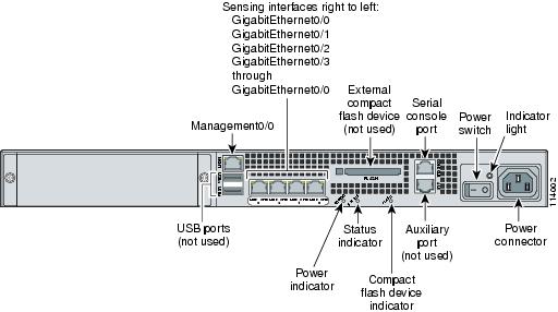
Figure 5-2 shows the back view of the IPS-4240 and IPS-4255.

Figure 5-2 IPS-4240 and IPS-4255 Back Panel Features

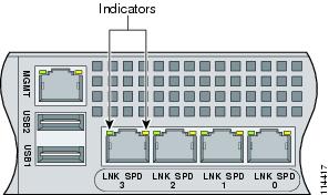
Figure 5-3 shows the four built-in Ethernet ports, which have two indicators per port.

Figure 5-3 Ethernet Port Indicators

Table 5-2 lists the back panel indicators.

Table 5-2 Back Panel Indicators 

Indicator
Color
Description

Left side

Green solid
Green blinking

Physical link
Network activity

Right side

Not lit
Green
Amber

10 Mbps
100 Mbps
1000 Mbps


Specifications

Table 5-3 lists the specifications for IPS-4240 and IPS-4255.

Table 5-3 IPS-4240 and IPS-4255 Specifications 

Dimensions and Weight
 

Height

1.75 in. (4.45 cm)

Width

17.5 in. (44.45 cm)

Depth

14.5 in. (36.83 cm)

Weight

20.0 lb (9.07 kg)

Form factor

1 RU, standard 19-inch rack-mountable

Expansion

One chassis expansion slot (not used)

Power
 

Autoswitching

100V to 240V AC

Frequency

47 to 63 Hz, single phase

Operating current

3.0 A

Steady state

150 W

Maximum peak

190 W

Maximum heat dissipation

648 BTU/hr, full power usage (65 W)

Environment
 

Temperature

Operating +32°F to +104°F (+0°C to +40°C)
Nonoperating -13°F to +158°F (-25°C to +70°C)

Relative humidity

Operating 5% to 95% (noncondensing)
Nonoperating 5% to 95% (noncondensing)

Altitude

Operating 0 to 9843 ft (3000 m)
Nonoperating 0 to 15,000 ft (4750 m)

Shock

Operating 1.14 m/sec (45 in./sec) ½ sine input
Nonoperating 30 G

Vibration

0.41 Grms2 (3 to 500 Hz) random input

Acoustic noise

60 dBa (maximum)


Accessories


Warning IMPORTANT SAFETY INSTRUCTIONS

This warning symbol means danger. You are in a situation that could cause bodily injury. Before you work on any equipment, be aware of the hazards involved with electrical circuitry and be familiar with standard practices for preventing accidents. Use the statement number provided at the end of each warning to locate its translation in the translated safety warnings that accompanied this device. Statement 1071

SAVE THESE INSTRUCTIONS

Warning Only trained and qualified personnel should be allowed to install, replace, or service this equipment. Statement 1030

IPS-4240 and IPS-4255 accessories kit contains the following:

DB25 connector

DB9 connector

Rack mounting kit—screws, washers, and metal bracket

RJ45 console cable

Two 6-ft Ethernet cables

Rack Mounting

To rack mount IPS-424 and IPS-4255, follow these steps:


Step 1 Attach the bracket to the appliance using the supplied screws.

You can attach the brackets to the holes near the front of the appliance.


Note The top hole on the left bracket is a banana jack you can use for ESD grounding purposes when you are servicing the system. You can use the two threaded holes to mount a ground lug to ground the chassis.


Step 2 Use the supplied screws to attach the appliance to the equipment rack.

Step 3 To remove the appliance from the rack, remove the screws that attach the appliance to the rack, and then remove the appliance.


Installing IPS-4240 and IPS-4255


Warning Only trained and qualified personnel should be allowed to install, replace, or service this equipment. Statement 1030

Caution Follow proper safety procedures when performing these steps by reading the safety warnings in Regulatory Compliance and Safety Information for the Cisco Intrusion Prevention System 4200 Series Appliance Sensor.

To install IPS-4240 and IPS-4255 on the network, follow these steps:


Step 1 Position the appliance on the network.

Step 2 Place the appliance in a rack, if you are rack mounting it.

For the procedure, see Rack Mounting.

Step 3 Attach the power cord to the appliance and plug it in to a power source (a UPS is recommended).

Step 4 Connect the cable as shown in Step 6 so that you have either a DB-9 or DB-25 connector on one end as required by the serial port for your computer, and the other end is the RJ-45 connector.


Note Use the console port to connect to a computer to enter configuration commands. Locate the serial cable from the accessory kit. The serial cable assembly consists of a 180/rollover cable with RJ-45 connectors (DB-9 connector adapter PN 74-0495-01 and DB-25 connector adapter PN 29-0810-01).


Note You can use a 180/rollover or straight-through patch cable to connect the appliance to a port on a terminal server with RJ-45 or hydra cable assembly connections. Connect the appropriate cable from the console port on the appliance to a port on the terminal server. See Connecting an Appliance to a Terminal Server for the instructions for setting up a terminal server.


Step 5 Connect the RJ-45 connector to the console port and connect the other end to the DB-9 or DB-25 connector on your computer.

Step 6 Attach the network cables.

GigabitEthernet0/0, GigabitEthernet0/1, GigabitEthernet0/2, and GigabitEthernet0/3 (from right to left) are sensing ports.

Management0/0 is the command and control port.

Step 7 Power on the appliance.

Step 8 Initialize the appliance.

For the procedure, see Initializing the Sensor.

Step 9 Upgrade the appliance with the most recent Cisco IPS software.

For the procedure, see Obtaining Cisco IPS Software.

You are now ready to configure intrusion prevention on the appliance.


For More Information

For the procedure for using HTTPS to log in to IDM, refer to Logging In to IDM.

For the procedures for configuring intrusion prevention on your sensor, refer to the following documents:

Installing and Using Cisco Intrusion Prevention System Device Manager 5.0

Configuring the Cisco Intrusion Prevention System Sensor Using the Command Line Interface 5.0