Feedback
Table Of Contents
Software and Hardware Requirements
Supported IDSM-2 Configurations
Installation and Removal Instructions
Installing IDSM-2
This chapter lists the software and hardware requirements of IDSM-2, and describes how to remove and install it. It contains the following sections:
•
Software and Hardware Requirements
•
•
•
Specifications
Table 7-1 lists the specifications for IDSM-2.
Software and Hardware Requirements
The following are the IDSM-2 software and hardware requirements:
•
•
•
•
•
•
•
•
Supported IDSM-2 Configurations
Table 7-2 lists the supported configurations for IDSM-2.
Table 7-2 Supported Configurations
RSPANSupervisor 1A
X
—
—
—
7.5(1)
—
Supervisor 1A with PFC1
X
X
X
—
7.5(1)
—
Supervisor 1A with PFC1 or MSFC1
X
X
X1
X
7.5(1)
Supervisor 1A-PFC2 or MSFC2
X
X
X3
X
7.5(1)
12.1(19)E1
Supervisor 2 with PFC2
X
X
X
—
7.5(1)
—
Supervisor 2 with PFC2 or MSFC2
X
X
X4
X
7.5(1)
12.1(19)E, 12.2(14)SY
Supervisor 720 (integrated PFC3 and MSFC3)
X
X
X
—
12.2(14)SX1 or later
1 VACL blocking by IDSM-2 is supported on Catalyst software and not on Cisco IOS for this configuration.
2 Cisco IOS is supported on Supervisor 1A with PFC1 or MSFC1; however, IDSM-2 is not supported on this configuration.
3 VACL blocking by IDSM-2 is supported on Catalyst software and not on Cisco IOS for this configuration.
4 VACL blocking by IDSM-2 is supported on Catalyst software and not on Cisco IOS for this configuration.
5 Supervisor 720 with Cisco IOS supports VACL deny statements; however, IDSM-2 cannot block with Cisco IOS-style VACLs.
Caution
Using the TCP Reset Interface
IDSM-2 has a TCP reset interface—port 1. IDSM-2 has a specific TCP reset interface because it cannot send TCP resets on its sensing ports.
If you have reset problems with IDSM-2, try the following:
•
•
Front Panel Features
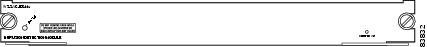
IDSM-2 (Figure 7-1) has a status indicator and a Shutdown button.
Figure 7-1 IDSM-2 Front Panel
Table 7-3 describes the IDSM-2 states as indicated by the status indicator.
To prevent corruption of IDSM-2, you must use the shutdown command to shut it down properly. For instructions on properly shutting down IDSM-2, see Step 1 of Removing IDSM-2. If IDSM-2 does not respond, firmly press the Shutdown button on the faceplate and wait for the Status indicator to turn amber. The shutdown procedure may take several minutes.
Caution
Installation and Removal Instructions
All Catalyst 6500 series switches support hot swapping, which lets you install, remove, replace, and rearrange modules without turning off the system power to the switch. When the system detects that a module has been installed or removed, it runs diagnostic and discovery routines, acknowledges the presence or absence of the module, and resumes system operation with no operator intervention.
Caution
This section contains the following topics:
Required Tools
Note
You need the following tools to install IDSM-2 in the Catalyst 6500 series switches:
•
•
•
Whenever you handle IDSM-2, always use a wrist strap or other grounding device to prevent serious damage from ESD. See Site and Safety Guidelines for more information.
WarningSlot Assignments
Note
The Catalyst 6006 and 6506 switch chassis each have six slots. The Catalyst 6009 and 6509 switch chassis each have nine slots. The Catalyst 6513 switch chassis has 13 slots. You can install IDSM-2 in the following ways:
•
•
Caution
Note
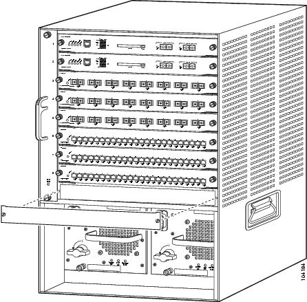
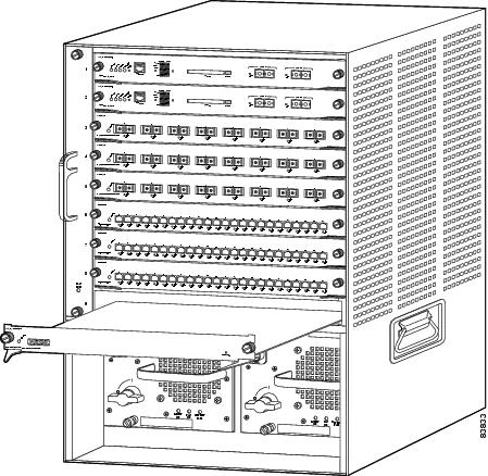
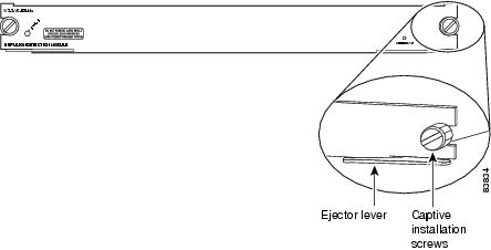
Installing IDSM-2
To install IDSM-2 in the Catalyst 6500 series switch, follow these steps:
Step 1
WarningFor more information, see Site and Safety Guidelines.
Step 2
Note
Step 3
Step 4
Step 5
Caution
Step 6
Step 7
Step 8
Caution
Note
Modulex has been inserted. This message does not appear, however, if you are connected to the Catalyst 6500 series switch through a Telnet session.Step 9
Step 10
Step 11
For the procedure, see Initializing the Sensor.
Step 12
For the procedure, refer to Configuring the Catalyst 6500 Series Switch for Command and Control Access to IDSM-2.
Step 13
For the procedure, see Obtaining Cisco IPS Software.
Step 14
For the procedure, refer to Configuring IDSM-2.
You are now ready to configure IDSM-2 for intrusion prevention.
For More Information
•
•
–
–
Verifying Installation
Verify that the switch acknowledges IDSM-2 and has brought it online.
To verify the installation, follow these steps:
Step 1
Step 2
cat6k> (enable) show moduleMod Slot Ports Module-Type Model Sub Status--- ---- ----- ------------------------- ------------------- --- --------1 1 2 1000BaseX Supervisor WS-X6K-SUP1A-2GE yes ok15 1 1 Multilayer Switch Feature WS-F6K-MSFC no ok2 2 48 10/100BaseTX Ethernet WS-X6248-RJ-45 no ok3 3 48 10/100/1000BaseT Ethernet WS-X6548-GE-TX no ok4 4 16 1000BaseX Ethernet WS-X6516A-GBIC no ok6 6 8 Intrusion Detection Mod WS-SVC-IDSM2 yes okMod Module-Name Serial-Num--- -------------------- -----------1 SAD041308AN15 SAD04120BRB2 SAD034754003 SAD073906RC4 SAL0751QYN06 SAD062004LVMod MAC-Address(es) Hw Fw Sw--- -------------------------------------- ------ ---------- -----------------1 00-d0-c0-cc-0e-d2 to 00-d0-c0-cc-0e-d3 3.1 5.3.1 8.4(1)00-d0-c0-cc-0e-d0 to 00-d0-c0-cc-0e-d100-30-71-34-10-00 to 00-30-71-34-13-ff15 00-30-7b-91-77-b0 to 00-30-7b-91-77-ef 1.4 12.1(23)E2 12.1(23)E22 00-30-96-2b-c7-2c to 00-30-96-2b-c7-5b 1.1 4.2(0.24)V 8.4(1)3 00-0d-29-f6-01-98 to 00-0d-29-f6-01-c7 5.0 7.2(1) 8.4(1)4 00-0e-83-af-15-48 to 00-0e-83-af-15-57 1.0 7.2(1) 8.4(1)6 00-e0-b0-ff-3b-80 to 00-e0-b0-ff-3b-87 0.102 7.2(0.67) 5.0(0.30)Mod Sub-Type Sub-Model Sub-Serial Sub-Hw Sub-Sw--- ----------------------- ------------------- ----------- ------ ------1 L3 Switching Engine WS-F6K-PFC SAD041303G6 1.16 IDS 2 accelerator board WS-SVC-IDSUPG . 2.0cat6k> (enable)Step 3
router# show moduleMod Ports Card Type Model Serial No.--- ----- -------------------------------------- ------------------ -----------1 48 48 port 10/100 mb RJ-45 ethernet WS-X6248-RJ-45 SAD0401012S2 48 48 port 10/100 mb RJ45 WS-X6348-RJ-45 SAL04483QBL3 48 SFM-capable 48 port 10/100/1000mb RJ45 WS-X6548-GE-TX SAD073906GH6 16 SFM-capable 16 port 1000mb GBIC WS-X6516A-GBIC SAL0740MMYJ7 2 Supervisor Engine 720 (Active) WS-SUP720-3BXL SAD08320L2T9 1 1 port 10-Gigabit Ethernet Module WS-X6502-10GE SAD071903BT10 3 Anomaly Detector Module WS-SVC-ADM-1-K9 SAD084104JR11 8 Intrusion Detection System WS-SVC-IDSM2 SAD0538060813 8 Intrusion Detection System WS-SVC-IDSM-2 SAD072405D8Mod MAC addresses Hw Fw Sw Status--- ---------------------------------- ------ ------------ ------------ -------1 00d0.d328.e2ac to 00d0.d328.e2db 1.1 4.2(0.24)VAI 8.5(0.46)ROC Ok2 0003.6c14.e1d0 to 0003.6c14.e1ff 1.4 5.4(2) 8.5(0.46)ROC Ok3 000d.29f6.7a80 to 000d.29f6.7aaf 5.0 7.2(1) 8.5(0.46)ROC Ok6 000d.ed23.1658 to 000d.ed23.1667 1.0 7.2(1) 8.5(0.46)ROC Ok7 0011.21a1.1398 to 0011.21a1.139b 4.0 8.1(3) 12.2(PIKESPE Ok9 000d.29c1.41bc to 000d.29c1.41bc 1.3 Unknown Unknown PwrDown10 000b.fcf8.2ca8 to 000b.fcf8.2caf 0.101 7.2(1) 4.0(0.25) Ok11 00e0.b0ff.3340 to 00e0.b0ff.3347 0.102 7.2(0.67) 5.0(1) Ok13 0003.feab.c850 to 0003.feab.c857 4.0 7.2(1) 5.0(1) OkMod Sub-Module Model Serial Hw Status--- --------------------------- ------------------ ------------ ------- -------7 Policy Feature Card 3 WS-F6K-PFC3BXL SAD083305A1 1.3 Ok7 MSFC3 Daughterboard WS-SUP720 SAD083206JX 2.1 Ok11 IDS 2 accelerator board WS-SVC-IDSUPG . 2.0 Ok13 IDS 2 accelerator board WS-SVC-IDSUPG 0347331976 2.0 OkMod Online Diag Status--- -------------------1 Pass2 Pass3 Pass6 Pass7 Pass9 Unknown10 Not Applicable11 Pass13 Passrouter#
Note
otherwhen IDSM-2 is first installed. After IDSM-2 completes the diagnostics routines and comes online, the status readsok. Allow up to 5 minutes for IDSM-2 to come online.For information on enabling a full memory test after verifying IDSM-2 installation, refer to Enabling Full Memory Tests.
Removing IDSM-2
This procedure describes how to remove IDSM-2 from the Catalyst 6500 series switch.
Warning
Caution
WarningTo remove IDSM-2, follow these steps:
Step 1
•
Note
•
–
set module shutdown module_number–
hw-module module module_number shutdown•
•
Note
Caution
Step 2
Step 3
Step 4
Step 5
Caution
Step 6
Note
Step 7
Step 8
For More Information
•
•
•
•
Enabling Full Memory Tests
When IDSM-2 initially boots, by default it runs a partial memory test. You can enable a full memory test in Catalyst software and Cisco IOS software.
This section describes how to enable memory tests, and contains the following topics:
Catalyst Software
Use the set boot device boot_sequence module_number mem-test-full command to enable a full memory test. The full memory test takes about 12 minutes.
To enable a full memory test, follow these steps:
Step 1
Step 2
console> enableStep 3
console> (enable) set boot dev cf:1 3 mem-test-fullDevice BOOT variable = cf:1Memory-test set to FULLWarning: Device list is not verified but still set in the boot string.console> (enable) set boot dev hdd:1 3 mem-test-fullDevice BOOT variable = hdd:1Memory-test set to FULLWarning: Device list is not verified but still set in the boot string.console> (enable)The set boot device command can either contain cf:1 or hdd:1.
Step 4
The full memory test runs.
Note
Cisco IOS Software
Use the hw-module module module_number reset mem-test-full command to enable a full memory test. The full memory test takes about 12 minutes.
To enable a full memory test, follow these steps:
Step 1
Step 2
router# hw-module module 9 reset mem-test-fullDevice BOOT variable for reset = <empty>Warning: Device list is not verified.Proceed with reload of module?[confirm]% reset issued for module 9router#Step 3
The full memory test runs.
Note
Resetting IDSM-2
If for some reason you cannot communicate with IDSM-2 through SSH, Telnet, or the switch session command, you must reset IDSM-2 from the switch console. The reset process requires several minutes.
This section describes how to reset IDSM-2, and contains the following topics:
Catalyst Software
To reset IDSM-2 from the CLI, follow these steps:
Step 1
Step 2
console> enableStep 3
console> (enable) reset module_number [hdd:1 | cf:1]
Note
Example:
console> (enable) reset 32003 Feb 01 00:18:23 %SYS-5-MOD_RESET: Module 3 reset from console//Resetting module 3... This may take several minutes.2003 Feb 01 00:20:03 %SYS-5-MOD_OK: Module 3 is online.console> (enable)
Caution
Cisco IOS Software
Use the hw-module module slot_number reset [hdd:1 | cf:1] command in EXEC mode to reset IDSM-2. The reset process takes several minutes. IDSM-2 boots into the boot partition you specify. If you do not specify the boot string, the default boot string is used.
To reset IDSM-2 from the CLI, follow these steps:
Step 1
Step 2
router# hw-module module module-number reset [hdd:1 | cf:1]
Note
Example:
router# hw-module module 8 resetDevice BOOT variable for reset =Warning: Device list is not verified.Proceed with reload of module? [confirm]% reset issued for module 8router#
Powering IDSM-2 Up and Down
You can remove and restore power to IDSM-2 through the switch CLI. This section describes how to power IDSM-2 up and down through the switch CLI, and contains the following sections:
Catalyst Software
Once you power off IDSM-2, you must power it up through the switch CLI.
Note
To power IDSM-2 up and down from the switch CLI, follow these steps:
Step 1
Step 2
console> enableStep 3
console> (enable) set module power up module_numberStep 4
console> (enable) set module power down module_number
Cisco IOS Software
Once you power off IDSM-2, you must power it up through the switch CLI.
Note
To power IDSM-2 up and down from the switch CLI, follow these steps:
Step 1
Step 2
router# configure terminalStep 3
router(config)# power enable module module_numberStep 4
router(config)# no power enable module module_number