
Table Of Contents
Installing a Circuit Board in a PIX 515
Installing a Circuit Board in a PIX 520 and Earlier Model
Installing a Circuit Board
Before using this chapter, refer to "," for instructions on how to open the case for each model of PIX Firewall. You can use the information in this chapter to install an interface card, such as for Ethernet, Token Ring, or FDDI, or a Private Link VPN card.
For DC models:
Warning
Before performing any of the following procedures, ensure that power is removed from the DC circuit. To ensure that all power is OFF, locate the circuit breaker on the panel board that services the DC circuit, switch the circuit breaker to the OFF position, and tape the switch handle of the circuit breaker in the OFF position.
For both AC and DC models:
Warning
Before working on a system that has an On/Off switch, turn OFF the power and unplug the power cord.
This chapter includes the following sections:
•
Installing a Circuit Board in a PIX 515
•
Installing a Circuit Board in a PIX 520 and Earlier Model
Installing a Circuit Board in a PIX 515
Note
Installing a circuit board in a PIX 515 requires the use of the PIX-515-UR unrestricted feature license. Without this feature license, any board you install in the PIX 515 is ignored.
The information in this section refers to both the AC and DC models of the PIX 515.
To install a circuit board in a PIX 515:
Step 1
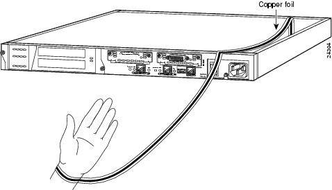
Locate the grounding strap from the accessory kit and attach it to bare metal inside the PIX 515 case as shown in .
Figure 7-1 Attaching the PIX 515 Grounding Strap
Step 2
Remove the screws from the rear assembly on the left and put the assembly aside.
Step 3
Insert a board through the cage opening and into the slot as shown in .
Figure 7-2 Inserting a Board into a PIX 515
Note
When you insert a four-port Ethernet board in the slot, the end of the board's connector extends past the end of the slot. This does not affect the use or operation of the board.
Step 4
Attach the back cover plate making sure that the connecting flange on the board goes through the slot on the back cover plate as shown in .
Figure 7-3 Attaching PIX 515 Back Cover Plate
Step 5
Attach the screw to hold the board's connecting flange to the cover plate, and the screws to attach the cover plate to the PIX 515 unit.
Step 6
Reattach the top cover.
Installing a Circuit Board in a PIX 520 and Earlier Model
To install a circuit board in a PIX 520 and earlier model:
Step 1
Locate the wrist grounding strap that accompanied the memory strip and connect one end to the PIX Firewall chassis, as shown in , and securely attach the other to your wrist so it contacts your bare skin.
Figure 7-4 Attaching Grounding Strap to Your Wrist and to the PIX Firewall
Step 2
Insert the new board, as shown in , and secure it using the screw provided with the board.
Figure 7-5 Installing the New Board
Step 3
Install the interface boards so that the leftmost board is the outside interface, as shown in , the next board to the left is the inside interface, and any other interfaces to the left (away from the power supply) of the inside interface. If you have version 4.4 and a four-port Ethernet board, refer to the section, "PIX Firewall with a Four-port Interface Card" in "."
Note
When adding a network interface or encryption card, install the new card in the first empty slot to the right of the existing network interface cards.
Figure 7-6 PIX Firewall Network Interfaces
Step 4
If you are installing a Private Link VPN board, insert the board in any remaining PCI slot after you install all required interface boards. Refer to for how a PCI slot appears compares to an ISA slot.
Figure 7-7
Identifying PCI Slots
Step 5
If you are installing the PIX Firewall Flash memory upgrade, place the new circuit board in the same slot from which you remove the existing circuit board.
Step 6
If you are installing an AccessPro router, the board requires two contiguous ISA slots.
Step 7
If you are installing a 4-port card, note that the board will appear to overlap the slot connector on the motherboard. illustrates how this appears.
Figure 7-8 4-Port Card Overlap
Connecting a FDDI Cable
After inserting a FDDI card into a PIX Firewall unit, connect the cable as shown in :
Figure 7-9 Connecting a FDDI Card Cable

 Feedback


