 Feedback Feedback
|
Table Of Contents
Mounting and Assembling a Cisco TelePresence System 1300
Required Tools and Accessories
Attaching the Mounting Bracket to a Wall With Wooden Studs
Attaching the Mounting Bracket to a Wall With Steel Studs
Attaching the Mounting Bracket to a Concrete, Concrete Block, or Brick Wall
Attaching the Light Reflector, Display, and Cabinet
Completing Installation and Cabling of the CTS-1300
Mounting and Assembling a Cisco TelePresence System 1300
Revised: May 8, 2009, OL-14522-01This chapter contains the procedure you use to mount and assemble a Cisco TelePresence System 1300 (CTS-1300). You can mount the CTS-1300 to any of the following wall types:
•
A wall with wooden studs
•
A wall with steel studs
•
A concrete, concrete block, or brick wall
This chapter includes the following sections:
•
Required Tools and Accessories
•
Attaching the Mounting Bracket to a Wall With Wooden Studs
•
Attaching the Mounting Bracket to a Wall With Steel Studs
•
Attaching the Mounting Bracket to a Concrete, Concrete Block, or Brick Wall
•
Attaching the Light Reflector, Display, and Cabinet
•
Completing Installation and Cabling of the CTS-1300
Required Tools and Accessories
The following tools are required to install the CTS-1300:
•
12mm socket (with socket extension)
•
5/8" drill bit (for wood and steel studs)
•
1/8" drill bit as pilot for finding stud edges (for steel studs only)
•
10mm masonry drill bit
•
Stud finder
•
10mm socket (with socket extension)
•
#3 Phillip screw driver
•
Tape measure
•
Pencil or other marking tool
•
Wire cutters for wire cable ties
•
Floor cable cover (for the Cisco Unified IP phone, VGA, and microphone cables between the CTS-1300 and the table)
•
Level
Parts List
See Table 3-1 for the list of parts that are required for this assembly procedure. Use the numbers in the "Key" column to refer to the parts in the illustrations.
CautionSome CTS-1300 elements are heavy, and metal edges can be very sharp. Protect your hands and eyes from injury by wearing safety gloves and glasses.
Attaching the Mounting Bracket to a Wall With Wooden Studs
This section contains the procedure you use to mount the CTS-1300 to the wall using wooden studs.
To attach the CTS-1300 mounting bracket to the wall, perform the following steps:
Step 1
Using a stud finder or other method, locate the studs in the wall.
Step 2
Mark the location of the two studs to use for the CTS-1300 mounting bracket.
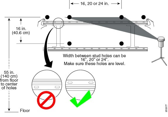
These studs can be 16, 20, or 24 inches (40.6, 51 or 61 centimeters) apart.
Step 3
Using the mounting bracket as a template, measure and drill six 1/4-inch holes as follows:
•
Drill four holes that go into the center of the stud: two holes for the top rail and two holes on the bottom rail.
Note
Each horizontal piece has two rows of holes. Make sure that you mount the bracket so that the screws go into the upper row of holes.
•
Drill two holes that go into the slot at each end of the top rail.
Tip
Use a level on the bracket when you measure the holes. Leveling the holes ensures that the bracket is horizontally level when it is mounted.
Figure 3-1 Measuring and Drilling Holes in the Wall for the CTS-1300 Mounting Bracket
Step 4
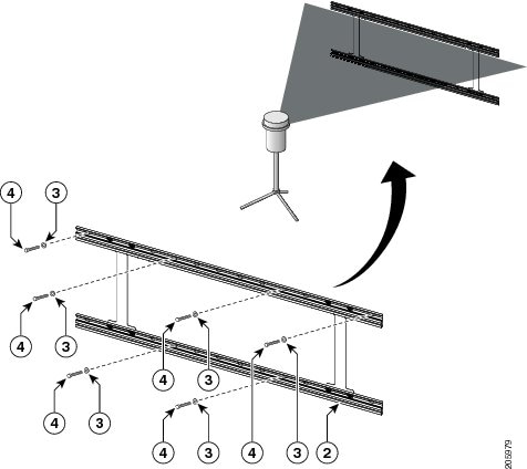
Attach the mounting bracket to the studs and wall using the 5/16-inch lag screws and washers. Make sure that the bracket is level.
Note
Mount the bracket so that the screws go into the upper row of holes on the bracket.
Figure 3-2 Attaching the Mounting Bracket to the Wall
Step 5
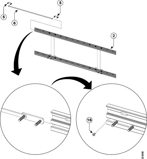
Install the nylon spacing strips into the lower slot of both horizontal bracket railings.
Step 6
Install the metal sliders on each side of the nylon spacing strips.
Note
Measure each side of the bracket to make sure that there is equal distance between the end of the bracket and the metal sliders.
Step 7
Insert a screw into each end of the rail after you insert the spacing strip and sliders.
Figure 3-3 Installing Nylon Spacing Strips and Metal Sliders into Wall Bracket
Step 8
Continue to the "Attaching the Light Reflector, Display, and Cabinet" section to complete installation of the CTS-1300.
Attaching the Mounting Bracket to a Wall With Steel Studs
This section contains the procedure you use to mount the CTS-1300 to the wall using steel studs.
To attach the CTS-1300 mounting bracket to the wall, perform the following steps:
Step 1
Using a stud finder or other method, locate the studs in the wall.
Step 2
Mark the location of the two studs to use for the CTS-1300 mounting bracket.
These studs can be 16, 20, or 24 inches (40.6, 51 or 61 centimeters) apart.
Step 3
Using the mounting bracket as a template, measure and drill six 5/8-inch holes as follows:
•
Drill four holes that go into the center of the stud: two holes for the top rail and two holes on the bottom rail.
Note
Each horizontal piece has two rows of holes. Make sure that you mount the bracket so that the screws go into the upper row of holes.
•
Drill two holes that go into the slot at each end of the top rail.
Tip
Use a level on the bracket when you measure the holes. Leveling the holes ensures that the bracket is horizontally level when it is mounted.
Figure 3-4 Measuring and Drilling Holes in the Wall for the CTS-1300 Mounting Bracket
Step 4
Insert the mounting anchors into the holes that you drilled by completing the following steps:
a.
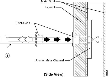
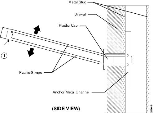
Using the anchors that are provided in the accessory kit, move the plastic straps on the anchor until the metal part of the anchor is parallel with the straps.
b.
Push the metal part of the anchor through the stud hole that you drilled.
Figure 3-5 Pushing the Anchor Through the Wall and Stud
Step 5
Turn the plastic straps on the anchor so that the metal part of the anchor is flush and vertical to the inner part of the stud or wall.
Step 6
Slide the plastic cap on the anchor until the cap is flush with the outer part of the wall.
Figure 3-6 Securing the Anchor and Cap to the Wall
Step 7
Snap off the plastic straps that protrude from the wall until the anchor assembly is flush with the wall. Push the straps from side to side to snap them off.
Figure 3-7 Removing the Plastic Straps
Step 8
Repeat Step 4 through Step 7 for the all holes in the wall.
Step 9
Attach the mounting bracket to the studs and wall using the screws and washers. Make sure that the bracket is level.
Note
Make sure that you mount the bracket so that the screws go into the upper row of holes on the bracket.
Figure 3-8 Attaching the Mounting Bracket to the Wall
Step 10
Install the nylon spacing strips into the lower slot of both horizontal bracket railings.
Step 11
Install the metal sliders on each side of the nylon spacing strips.
Note
Measure each side of the bracket to make sure that there is equal distance between the end of the bracket and the metal sliders.
Step 12
Insert a screw into each end of the rail after you insert the spacing strip and sliders.
Figure 3-9 Installing Nylon Spacing Strips and Metal Sliders into Wall Bracket
Step 13
Continue to the "Attaching the Light Reflector, Display, and Cabinet" section to complete installation of the CTS-1300.
Attaching the Mounting Bracket to a Concrete, Concrete Block, or Brick Wall
This section contains the procedure you use to mount the CTS-1300 to the wall concrete, concrete block, or brick wall.
To attach the CTS-1300 mounting bracket to the wall, perform the following steps:
Step 1
Measure and drill the holes in the wall by completing the following steps:
a.
Using the mounting bracket as a template, measure six 10mm holes into the wall using Figure 3-10 as a reference.
Note
Each horizontal bracket piece has two rows of holes. Make sure that you mount the bracket so that the screws go into the upper row of holes.
Tip
Use a level on the bracket when you measure the holes. Leveling the holes ensures that the bracket is horizontally level when it is mounted.
Figure 3-10 Measuring Holes in the Wall for the CTS-1300 Mounting Bracket
b.
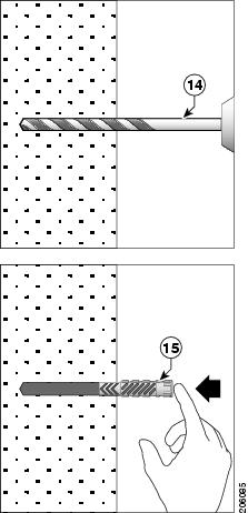
Drill the holes using the 10mm masonry drill bit that is included with the accessory kit; then, push the anchors into the holes that you drilled. Drill at least 75 millimeters into the concrete or brick wall.
Note
Make sure that each mounting point can withstand a pull-out force of 32 pounds (14.5 kilograms).
Figure 3-11 Inserting Anchors into the Drilled Holes
Step 2
Attach the mounting bracket to the wall using the screws and washers. Make sure that the bracket is level.
Note
Make sure that you mount the bracket so that the screws go into the upper row of holes on the bracket.
Figure 3-12 Attaching the Mounting Bracket to the Wall
Step 3
Install the nylon spacing strips into the lower slot of both horizontal bracket railings.
Step 4
Install the metal sliders on each side of the nylon spacing strips.
Note
Measure each side of the bracket to make sure that there is equal distance between the end of the bracket and the metal sliders.
Step 5
Insert a screw into each end of the rail after you insert the spacing strip and sliders.
Figure 3-13 Installing Nylon Spacing Strips and Metal Sliders into Wall Bracket
Step 6
Continue to the "Attaching the Light Reflector, Display, and Cabinet" section to complete installation of the CTS-1300.
Attaching the Light Reflector, Display, and Cabinet
To attach the light reflector and display to the mounting bracket, and to attach the cabinet to the wall, complete the following steps:
Step 1
Remove the light reflector from its packaging.
Step 2
Remove the nuts that attach the side light covers to each side of the light reflector and remove the covers.
Note
Save the nuts and washers
Figure 3-14 Removing the Side Light Covers
Step 3
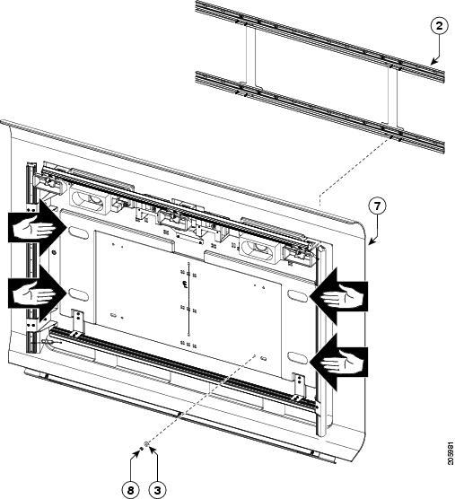
Using at least two people, lift the light reflector and mount it on the studs of the metal sliders.
Step 4
Attach the light reflector to the four inside studs of the metal sliders using the nuts and washers.
Note
Be sure that you only attach the inside studs of each slider.
Figure 3-15 Attaching the Light Reflector to the Metal Sliders
Step 5
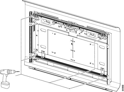
Using a 5/8-inch drill bit, drill holes around the perimeter of the light reflector.
Use the holes in the light reflector as a template for the holes that you drill.
Figure 3-16 Drilling Holes For Light Reflector Anchor Pieces
Step 6
Insert anchors in each drilled hole by completing Step 4 through Step 7 in the "Attaching the Mounting Bracket to a Wall With Steel Studs" section.
Step 7
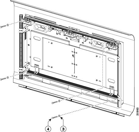
Secure the light reflector to the wall with the screws and washers.
Figure 3-17 Securing the Light Reflector to the Wall Using Screws and Washers
Step 8
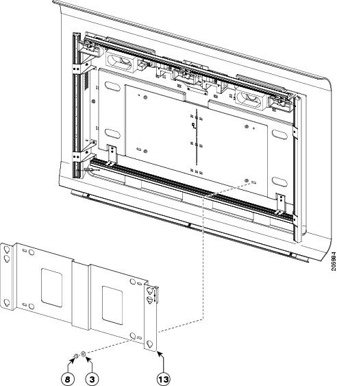
Hang the display mounting plate on the metal sliders, then attach the outer studs of each slider to the mounting plate using the screws and washers.
Figure 3-18 Attaching the Display Mounting Plate to the Metal Sliders
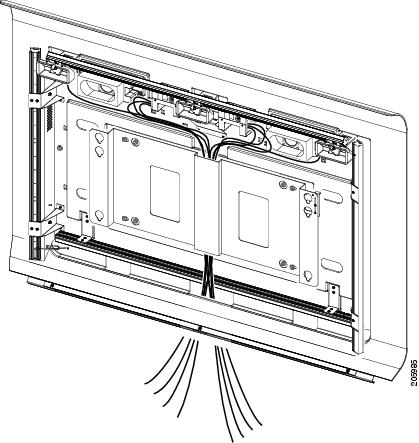
Figure 3-19 Attaching the Display Mounting Plate to the Metal Sliders—Cable Routing Detail
Step 9
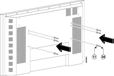
Remove the display from its packaging.
Step 10
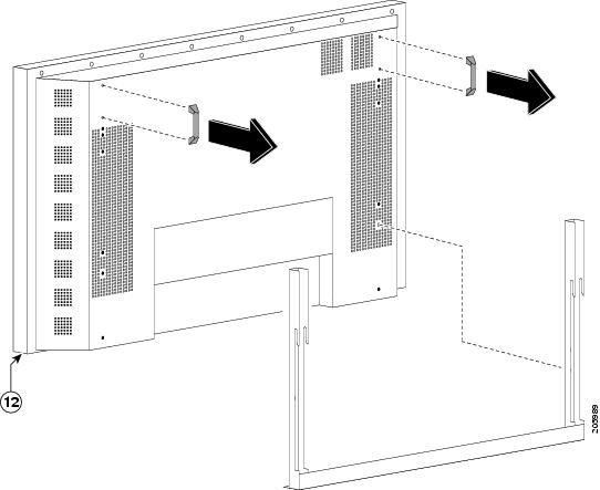
Remove the handles and universal mounting bracket from the rear of the display.
Note
Save the screws for this mounting hardware. You reuse these screws in Step 11.
Figure 3-20 Removing the Hardware from the Rear of the Display
Step 11
Attach the mounting buttons to the rear of the display reusing the screws you removed in Step 10.
You use these buttons to hang the display onto the display mounting plate.
Figure 3-21 Attaching the Mounting Buttons to the Rear of the Display
Step 12
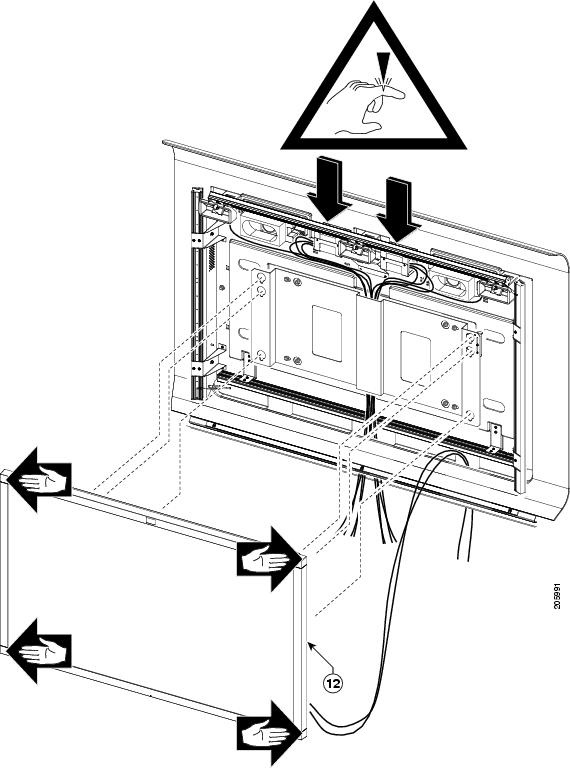
Using at least three people (one person on each side of the display and one person in the center of the display), lift the display and hang the six buttons over and into the keyhole slots in the mounting plate.
Tip
Align the Cisco logo on the top center of the display with the center positional microphone in the top center of the light reflector.
Warning
Take care to not pinch your fingers between the display and the metal brackets on the light reflector; these brackets fit very closely to the display.
Figure 3-22 Mounting the Display to the Display Mounting Bracket
Step 13
Reattach the side light covers to the light reflector, using the nuts and washers you removed in Step 2.
See Figure 3-14 for the location of the studs where you attach the nuts.
Note
Align the rear flange of the side light cover to the top edge of the recess in the light reflector, and use a level on each side of the reflector to make sure that it is vertically level.
Figure 3-23 Reattaching the Side Light Covers
Step 14
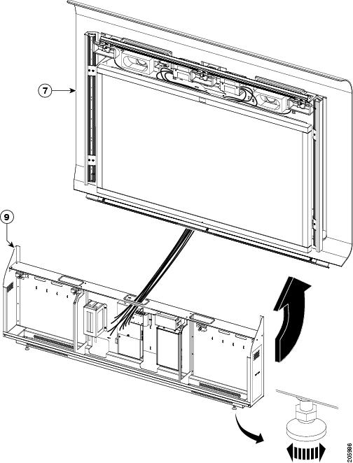
Using two people, install the cabinet by completing the following steps:
a.
Lean the cabinet so that the top part of it leans toward the wall.
b.
Route the cables through the center slot on top of the cabinet.
c.
Slide the lower part of the cabinet so that it sits flush against the wall underneath the light reflector.
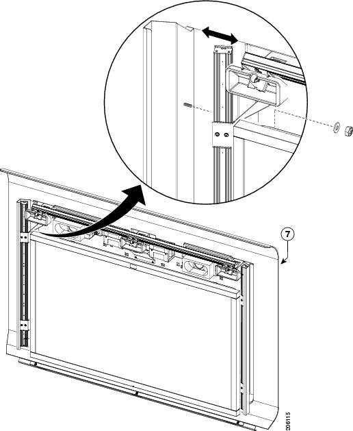
Tip
Adjust the bar that is attached to the light reflector by loosening the three screws and raising or lowering the bar as needed.
Figure 3-24 Installing the Cabinet
Step 15
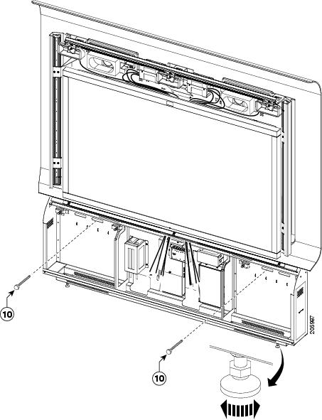
Secure the cabinet to the wall using the toggle bolts.
Figure 3-25 Attaching the Cabinet to the Wall
Completing Installation and Cabling of the CTS-1300
To perform the final installation tasks and route and attach the cables for the CTS-1300, complete the steps in the following section.
Step 1
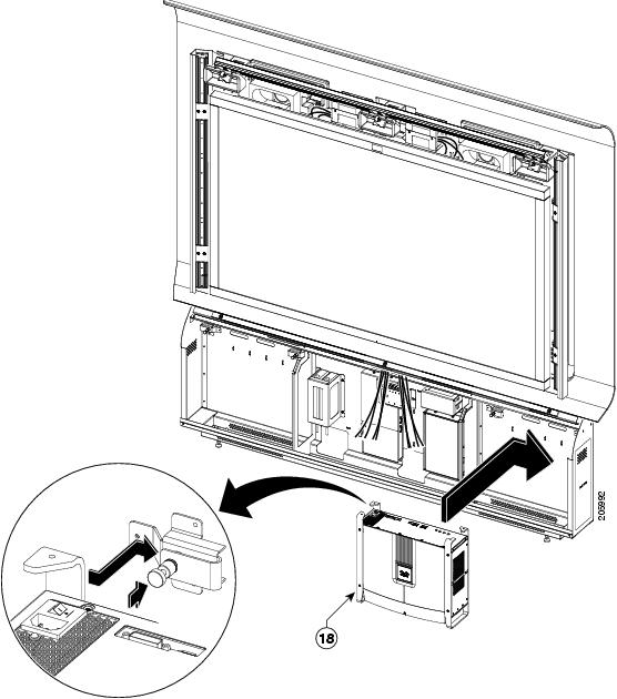
Install the codec into the cabinet by completing the following steps:
a.
Insert the codec into the right side of the cabinet.
b.
Slide the codec from the left to the right left until the top of the codec slides past the spring-loaded posts inside the cabinet.
Note
In some cases, you might have to lift the posts and turn them clockwise prior to installation.
c.
Turn the posts counter-clockwise to lower the posts and lock the codec into place.
Figure 3-26 Installing the Codec
Step 2
Install the bezel around the display by completing the following steps:
a.
Using at least two people, lift and place the bezel around the perimeter of the display.
b.
Place the clips over the posts on each corner of the bezel (four posts and clips in total) to secure it to the edges of the display.
Figure 3-27 Attaching the Bezel to the Display
Step 3
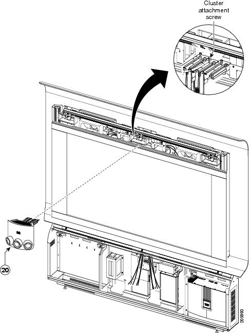
Attach the camera and processors by completing the following steps:
a.
Attach the camera to the assembly by sliding the camera assembly into the metal tab above the display.
b.
Insert the camera processors into the metal boxes that are in the light reflector on each side of the camera. Two processors go on the left side, and one processor goes on the right side.
c.
Connect the Ethernet and video cables that are attached to the light reflector to the processors.
Note
The cables that are attached to the light reflector are labeled; attach the correct cables to each processor using the labels, and make a note of each connection The two processors on the right attach to the left and center cameras, and the processor on the right attaches to the right camera.
d.
Connect the cables between the camera and the processors.
Figure 3-28 Attaching the Camera to the CTS-1300 Assembly
Step 4
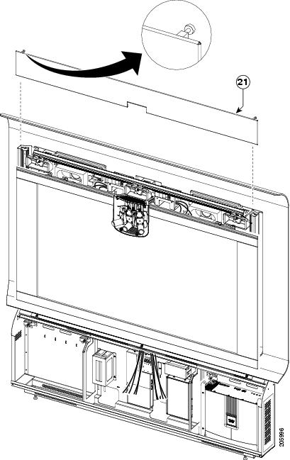
Attach the speaker cover to the CTS-1300 assembly by sliding the cover from the top into its slot in the bezel. Tighten the knob on each end of the speaker cover to attach it to the light reflector.
Figure 3-29 Attaching the Speaker Cover to the Cabinet
Step 5
Attach and route the cables for the codec.
Figure 3-30 Cable Routing Guide for CTS-1300
Step 6
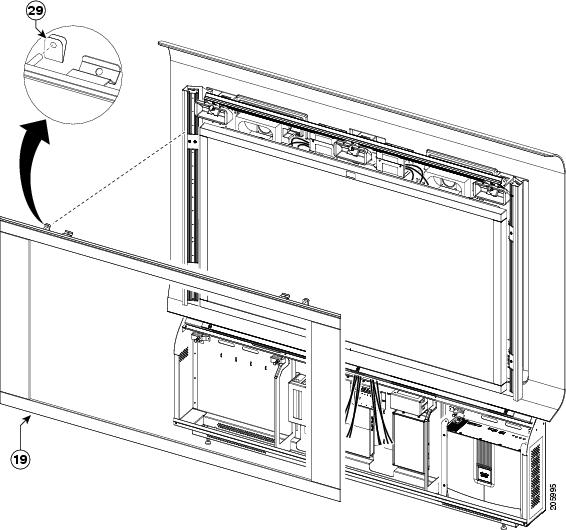
Attach the cabinet cover to the cabinet by completing the following steps:
a.
Set the lower part of the cabinet cover into the slotted groove in the lower part of the cabinet.
b.
Align the tabs in the upper part of the cabinet cover with the slots in the upper part of the cabinet.
c.
Rock the cover forward until the tabs go into the slots.
Tip
Adjust the bar attached to the top of the light reflector by loosening the three screws and raising or lowering the bar as required.
Figure 3-31 Attaching the Cabinet Cover to the Cabinet


