 Feedback Feedback
|
Table Of Contents
1550 Series GPS Hardware Mounting Guide
1552C/CU Mounted on PMK; Unit Horizontal
1552C/1552CU Mounted on SMK; Unit Horizontal
1552CU Mounted on PMK; Unit Vertical
1552E/EU Mounted on PMK; Unit Vertical
1552I Mounted on PMK; Unit Horizontal
1552C/1552I Mounted on a Vault; Unit Horizontal
Obtaining Documentation and Submitting a Service Request
1550 Series GPS Hardware Mounting Guide
February 2013OL-28798-01Contents
Overview
The purpose of this document is to provide information on routing and securing the cable for the GPS module (AIR-ACC1550-GPS1 and AIR-ACC1550-GPS2) that is available as a factory-installed option with the Cisco 1552C/CU/E/EU/I access points.
The GPS module is shipped already assembled, tethered, and mounted in the predominant as-used orientation for each product configuration. Depending on the mounting configuration used for the access point, the GPS antenna may need to be repositioned, and the GPS cable must be routed and secured.
The following illustrations show how to reposition the GPS antenna and, if necessary; route the GPS cable.
Mounting Configurations
The 1550 Series of access points supports use of the GPS option in the following configurations:
•
1552C/CU Mounted on PMK; Unit Horizontal
•
1552C/1552CU Mounted on SMK; Unit Horizontal
•
1552CU Mounted on PMK; Unit Vertical
•
1552E/EU Mounted on PMK; Unit Vertical
•
1552I Mounted on PMK; Unit Horizontal
•
1552C/1552I Mounted on a Vault; Unit Horizontal
1552C/CU Mounted on PMK; Unit Horizontal
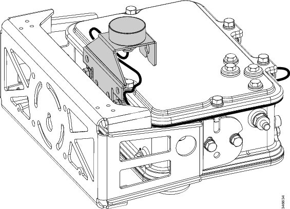
To mount the 1552C/155CU access point with the GPS option using the pole mount kit (PMK), route the GPS cable as shown in Figure 1, and anchor the cable to the bracket hardware using cable ties where necessary to secure excess cable length.
Figure 1 1552C/1552CU Access Point Mounted on PMK - Horizontal (1552C is shown)
1552C/1552CU Mounted on SMK; Unit Horizontal
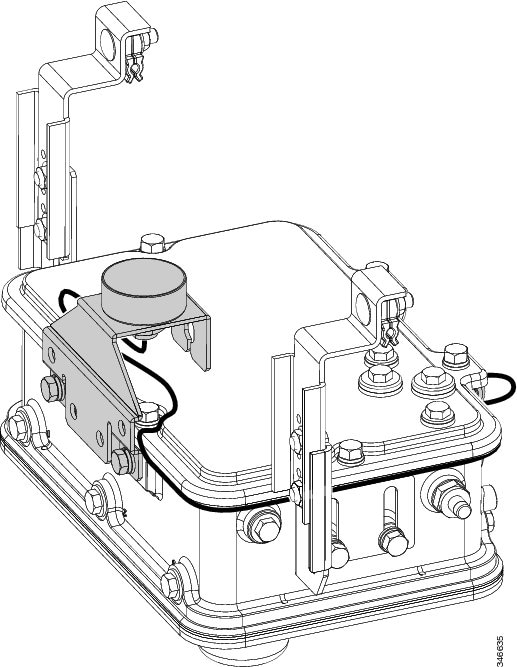
To mount the 1552C or 1552CU access point with the GPS option using the strand mount kit (SMK), route the GPS cable as shown in Figure 2, and anchor the cable to the bracket hardware with cable ties where necessary to secure excess cable length.
Figure 2 Access Point 1552C/1552CU Mounted on SMK - Horizontal (1552C is shown)
1552CU Mounted on PMK; Unit Vertical
The 1552CU access point with the GPS option is shipped with the GPS antenna and bracket in a position that is appropriate to mount the unit horizontally on a strand as shown in Figure 2.
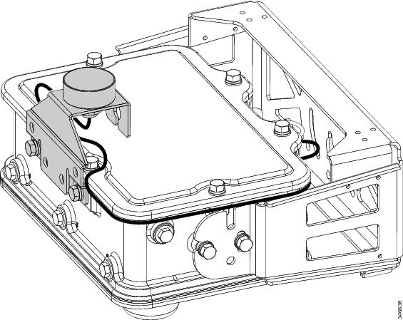
To mount the 1552CU unit using the pole mount kit (PMK) in a vertical orientation, the GPS antenna and bracket must be repositioned as shown in Figure 3. After repositioning, torque the bolts to 6-7 ft-lbs.
After repositioning the GPS antenna and bracket, complete the configuration of the 1552CU access point by routing the GPS cable as shown in Figure 3 and anchoring the cable to the bracket hardware with cable ties where necessary to secure excess cable length.
Figure 3 1552CU Mounted on PMK - Vertical
1552E/EU Mounted on PMK; Unit Vertical
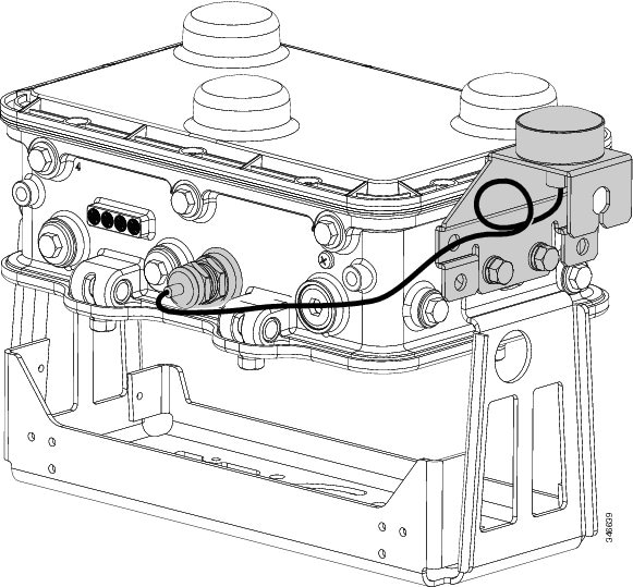
To mount the 1552E or 1552EU access point with the GPS option using the pole mount kit (PMK), route the GPS cable as shown in Figure 4 and anchor the cable to the bracket hardware with cable ties where necessary to secure excess cable length.
Figure 4 1552E/1552EU Mounted on PMK - Vertical
1552I Mounted on PMK; Unit Horizontal
To mount the 1552I access point with the GPS option using the pole mount kit (PMK), route the GPS cable as shown in Figure 5 and anchor the cable to the bracket hardware with cable ties where necessary to secure excess cable length.
Figure 5 1552I Mounted on PMK - Horizontal, Reversed
1552C/1552I Mounted on a Vault; Unit Horizontal
The 1552C access point with the GPS option is shipped with the GPS antenna and bracket in the position shown in Figure 1. The 1552I access point with the GPS option is shipped with the GPS antenna and bracket in the position shown in Figure 5.
To mount the 1552C or 1552I unit in a vault using the PMK, the GPS antenna and bracket must be repositioned as shown in Figure 6. After repositioning, torque the bolts to 6-7 ft-lbs.
After repositioning the GPS antenna and bracket, complete the configuration of the 1552C or 1552I access point by routing the GPS cable as shown in Figure 6 and anchoring the cable to the bracket hardware with cable ties where necessary to secure excess cable length.
Figure 6 1552C/1552I Mounted on Vault - Horizontal (1552I is shown)
Obtaining Documentation and Submitting a Service Request
For information on obtaining documentation, submitting a service request, and gathering additional information, see the monthly What's New in Cisco Product Documentation, which also lists all new and revised Cisco technical documentation:
http://www.cisco.com/en/US/docs/general/whatsnew/whatsnew.html
Subscribe to the What's New in Cisco Product Documentation as an RSS feed and set content to be delivered directly to your desktop using a reader application. The RSS feeds are a free service. Cisco currently supports RSS Version 2.0.
Cisco and the Cisco logo are trademarks or registered trademarks of Cisco and/or its affiliates in the U.S. and other countries. To view a list of Cisco trademarks, go to this URL: www.cisco.com/go/trademarks. Third-party trademarks mentioned are the property of their respective owners. The use of the word partner does not imply a partnership relationship between Cisco and any other company. (1110R)
Any Internet Protocol (IP) addresses and phone numbers used in this document are not intended to be actual addresses and phone numbers. Any examples, command display output, network topology diagrams, and other figures included in the document are shown for illustrative purposes only. Any use of actual IP addresses or phone numbers in illustrative content is unintentional and coincidental.
© 2013 Cisco Systems, Inc. All rights reserved.


