![]() |
Table Of Contents
Installing the Hardware
Note
Before you install the CSG into the Catalyst 6000 series switch, make sure the switch meets the hardware and software requirements listed in the Release Notes for Cisco Content Services Gateway 3.1(3)C5(5).
This chapter describes how to install the CSG into the Catalyst 6500 series switch or Cisco 7600 series router, and contains these sections:
Front Panel Description
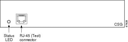
Figure 2-1 shows the CSG front panel. (The RJ-45 connector is covered by a removable plate.)
Figure 2-1 The CSG Front Panel
Status LED
When the CSG powers up, it initializes various hardware components and communicates with the supervisor engine. The Status LED indicates the supervisor engine operations and the initialization results.
During the normal initialization sequence, the status LED changes from off to red, to orange, and then to green. Table 2-1 describes the Status LED operation.
RJ-45 Connector
The RJ-45 connector, which is covered by a removable plate, is used to connect a management station device or a test device. This connector is used by field engineers to perform testing and to obtain dump information.
Installing the CSG
The following sections describe how to install the CSG:
Note
Before installing the CSG, you must install the Catalyst 6000 series switch or Cisco 7600 series router chassis and at least one supervisor engine. For information on installing the switch chassis, see the Catalyst 6000 Series Switch Installation Guide, or the Cisco 7609 Router Installation Guide.
Before installing the CSG, make sure that the following items are available:
•
Catalyst 6000 series switch or Cisco 7600 series router chassis
•
Management station that is available through a Telnet or a console connection to perform configuration tasks
•
Flat-blade screwdriver
•
Wrist strap or other grounding device
•
Antistatic mat or antistatic foam
When you install the CSG, keep the following considerations in mind:
•
See the Cisco 7600 Series Router Module Installation Guide if you are installing the CSG module into a Cisco 7600 series router.
•
All modules, including the supervisor engine (if you have redundant supervisor engines), support hot swapping. You can add, replace, or remove modules without interrupting the system power or causing other software or interfaces to shut down. For more information about hot-swapping modules, see the Catalyst 6500 Series Switch Module Installation Guide.
Warning
During this procedure, wear grounding wrist straps to avoid ESD damage to the card. Do not directly touch the backplane with your hand or any metal tool, or you could shock yourself.
To install the CSG into the Catalyst 6000 series switch, perform these steps:
Step 1
Make sure you take the necessary precautions to prevent ESD damage.
Step 2
Choose a slot for the CSG. See Figure 2-2 for slot numbers on a Catalyst 6000 series switch.
Note
Slot 1 is reserved for the supervisor engine. Slot 2 can contain an additional supervisor engine in case the supervisor engine in slot 1 fails. If a redundant supervisor engine is not required, you can insert the CSG in slots 2 through 6 on the 6-slot chassis, slots 2 through 9 on a 9-slot chassis, or slots 2 through 13 on the 13-slot chassis.
Figure 2-2 Slot Numbers on Catalyst 6000 Series Switches
Step 3
Check that there is enough clearance to accommodate any interface equipment that you are connecting directly to the supervisor engine or switching module ports.
Tip
If possible, place switching modules between empty slots that contain only switching-module filler plates (Cisco part number 800-00292-01).
Warning
Blank faceplates (filler panels) serve three important functions: they prevent exposure to hazardous voltages and currents inside the chassis; they contain electromagnetic interference (EMI) that might disrupt other equipment; and they direct the flow of cooling air through the chassis. Do not operate the system unless all cards and faceplates are in place.
Step 4
Loosen the captive installation screws that secure the switching module filler plate (or an existing switching module) to the desired slot.
Step 5
Remove the switching module filler plate (or an existing switching module).
Step 6
Hold the face of the CSG with one hand, and place your other hand under the carrier support. Do not touch the printed circuit boards or connector pins.
Step 7
Place the CSG in the slot. Align the notch on the sides of the switching module carrier with the groove in the slot. (See Figure 2-3.)
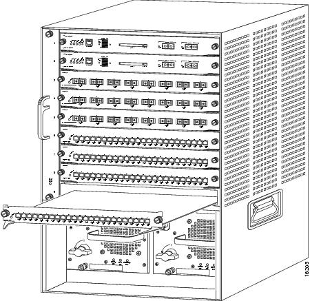
Figure 2-3 Installing Modules in the Catalyst 6000 Series Switch
Step 8
Keep the CSG at a 90-degree angle to the backplane and carefully slide the CSG into the slot until the switching module faceplate contacts the ejector levers. (See Figure 2-4.)
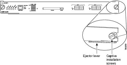
Figure 2-4 Ejector Levers and Captive Installation Screws
Step 9
Using the thumb and forefinger of each hand, simultaneously push in the left and right levers to fully seat the CSG in the backplane connector.
CautionAlways use the ejector levers when installing or removing the CSG. A module that is partially seated in the backplane can cause system problems.
If you perform a hot swap, the console displays the message "Module n has been inserted." This message does not appear, however, if you are connected to the Catalyst 6000 series switch through a Telnet session.
Step 10
Use a screwdriver to tighten the captive installation screws on the left and right ends of the CSG.
This completes the CSG installation procedure.
Verifying the Installation
When you install the CSG into the Catalyst 6000 series switch or Cisco 7600 series router, the module goes through a boot sequence that requires no intervention. At the successful conclusion of the boot sequence, the green Status LED lights and remains on. If the Status LED does not show green, or shows a different color, see Table 2-1 to determine the module's status.