Introduction
Intent
Preface
Summary
Unified Communications Management Requirements
Unified Communications Device Instrumentation
Unified Communications Support Elements
Unified Communications Instrumentation Sources
Unified Communications Support Element Instrumentation Sets
Unified Communications Physical Device Instrumentation
Unified Communications NMS Architecture
Unified Communications Fault Management
Support Element Management Configuration
Event Correlation and Downstream Suppression
Actionable Events
Nonactionable Events
QoS Monitoring
Unified Communications Performance Management
Unified Communications Performance Metrics
Unified Communications Service Quality Metrics
Unified Communications Configuration Management (FCAPS Defined)
Configuration Management Planning
Configuration Management Compliance
Glossary of Terms
References
Introduction
Intent
This white paper provides a high-level framework that can be used to develop and deploy management architecture for unified communications environments.
Preface
This white paper is a companion to the foundational Network Management Systems (NMS) Architecture White Paper. It builds on concepts introduced in the foundational NMS Architecture White Paper, and familiarization with these essential concepts is suggested as a prerequisite to this paper.
This paper uses International Telecommunications Union (ITU)1 and IT Service Management Forum (itSMF)2 references and terminology. Specifically, several of the ITU FCAPS (Fault, Configuration, Accounting, Performance, and Security) model functional areas and the itSMF IT Information Library (ITIL)3 processes are incorporated into this paper. The intent of using both FCAPS functional areas and ITIL processes in this paper is to demonstrate and explain their relationships and dependencies in an overall IT services governance model.
Summary
Unified communications can provide significant productivity and cost benefits as communication methods coverage onto a common IP transport medium. While this convergence on its face implies that unified communications becomes just another set of IP-based applications to support, customer availability and reliability expectations for unified communications generally far exceed those of traditional IP data applications. These high expectations are mainly predicated on interdependencies between effective organizational operations and reliable communication services. Further, unified communications voice applications also have unique network behavioral requirements relative to traditional IP data applications with respect to data-transmission rates as well as tolerance to packet delay, loss, and variable delay in delivery, also called jitter. Whereas traditional IP data applications typically transmit large amounts of data in bursts that are tolerant to reasonable delay, loss, and jitter, unified communications voice traffic continuously transmits relatively small amounts of data that are less tolerant to delay, loss, and jitter than traditional IP applications. High availability and unique network support requirements necessitate that particular attention be paid to management of unified communications environments.
Unified Communications Management Requirements
As traditional voice and data networks converge into a common unified communications environment, interdependencies across supporting network and IT systems dramatically increase. Although substantial efficiencies are gained, the interdependencies formed as a result of this convergence demand higher component availability throughout the environment to provide stable and reliable unified communications services to end customers. Effective unified communications management application of traditional network management disciplines to all unified communications foundational and support systems, such as network infrastructure and supporting applications, as well as the unified communications applications themselves. Solid foundational network management practices are the basis for effective unified communications management. More information about foundational network management leading practices can be found in the foundational NMS Architecture White Paper.
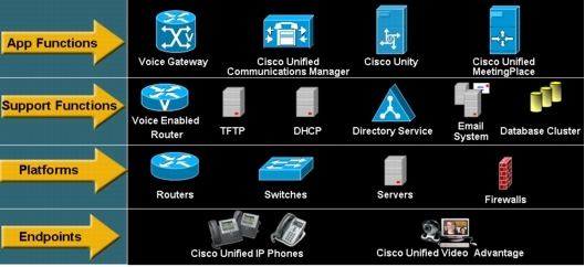
Unified communications management can be segmented into layers based on the role of each logical element that supports unified communications environments. Figure 1 illustrates these unified communications management layers and where each role-based support element resides.
Figure 1. Unified Communications Management
The unified communications management layers define interdependencies between each element; application functions depend on support functions, support functions depend on platforms, and endpoints depend on platforms. For example, Cisco Unity depends on directory service, e-mail system, and database cluster support functions. In turn, these systems depend on server platforms.
Effective unified communications management requires proper management of all support elements at each layer. In many cases one device may contain multiple unified communications support elements. For example, a traditional IP router may also serve as a voice-enabled router (meaning it facilitates voice-over-IP [VoIP]-related traffic) and possibly even a voice gateway. By identifying the unified communications support roles of each device throughout the environment, comprehensive unified communications management can be achieved.
Unified Communications Device Instrumentation
Simply put, device instrumentation involves the procurement of meaningful data from devices. For unified communications, this procurement entails gathering useful data from devices that have at least one unified communications service support role. As mentioned previously, in many cases one device may serve multiple unified communications support roles, and effective unified communications management requires proper management of all of these logical support roles. A modular approach to device instrumentation can be employed to ensure comprehensive instrumentation is achieved based on the unified communications support roles of a particular device. The process to implement modularized unified communications instrumentation is rather straightforward:
1. Identify all possible unified communications logical support elements.
2. Identify all possible unified communications instrumentation sources for the identified elements.
3. Create sets of instrumentation for each unified communications logical support element using identified sources.
4. Apply applicable instrumentation sets to each physical device based on support roles to meet overall support requirements.
Using a "divide-and-conquer" instrumentation strategy will help guarantee comprehensive device instrumentation for currently deployed infrastructure as well as create efficiencies in deploying complete instrumentation for future devices.
The following subsections outline a guide that can be used in the development of a modular strategy to unified communications device instrumentation.
Unified Communications Support Elements
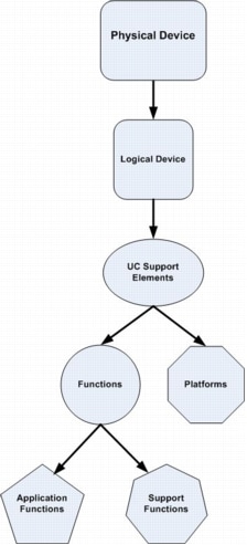
Unified communications support elements describe logical service roles that reside on a device and have unique instrumentation source data; devices may have multiple logical support elements. A nomenclature can be applied to classify support elements based on the unified communications management layers described previously. Figure 2 illustrates this taxonomy.
Figure 2. Classification of Support Elements Based on the Unified Communications Management Layers
Each physical device has one or more logical devices. For example, a standard server has one device instance while a server virtual machine can host multiple logical (guest) device instances. Network infrastructure device chassis may also contain separate logical routing and switching devices, or these functions may be combined on the same logical device. Each of these logical devices has one platform and one or more functions. Functions relate to specific unified communications functional roles such as gateway or gatekeeper or voice applications such as Cisco® Unified Communications Manager. Platforms describe common infrastructure that support functions such as Cisco IOS® Software or Microsoft Windows. For example, the voice gateway function resides on a Cisco IOS Software platform, and the Cisco Unified Communications Manager function resides either on a Windows or a Linux platform.
Functions can be further subdivided into two groups:
• Application functions
• Support functions
Application functions are responsible for delivery of service to the end user (for example, Cisco Unity Voicemail), whereas support functions provide services to the application functions (for example, Microsoft Exchange message store for Cisco Unity Voicemail).
To identify all possible unified communications support elements, begin with the set of unified communications applications that are in use because they will determine which support elements are needed. For example, if only Cisco Unified Communications Manager 5.0 is currently deployed, there is no need to create an instrumentation set for Windows platforms, because Cisco Unified Communications Manager 5.0 is supported only on a Linux platform. Table 1 is an example of unified communications support element identification based on a potential unified communications environment.
Table 1. Unified Communications Support Element Identification Based on Potential Unified Communications Environment
Application
Support Functions
Platform
Support Elements Needed
Cisco Unified Communications Manager 4.3
Microsoft SQL Server 2000
Embedded Lightweight Directory Access Protocol (LDAP) DC
Embedded Trivial File Transfer Protocol (TFTP) service
Microsoft DHCP Server
Microsoft Windows 2003
Cisco Unified Communications Manager 4.x function
Microsoft SQL Server 2000 function
Microsoft Windows 2003 (including Dynamic Host Configuration Protocol [DHCP]) platform
Enhanced Internet Gateway Routing Protocol (EIGRP) IP routing
Differentiated Services Code Point (DSCP) Low Latency Queuing (LLQ) Quality of Service (QoS)
Cisco IOS Software
H.323 Cisco IOS PRI Voice Gateway function
IP Routing function
DSCP LLQ QoS function
Cisco IOS Software platform
Cisco IOS Software Voice-Enabled Router
EIGRP IP Routing
DSCP LLQ QoS
Cisco IOS Software
IP Routing function
DSCP LLQ QoS function
Cisco IOS Software platform
Cisco IOS Software Voice Support Switch
Ethernet Mulitlayer Switching (MLS)
Cisco IOS Software
Ethernet MLS function
Cisco IOS Software platform
Unified Communications Instrumentation Sources
After all support elements have been identified, all possible instrumentation sources for these support elements should be enumerated. Following are brief descriptions of all possible unified communications instrumentation sources.
Internet Control Message Protocol
Internet Control Message Protocol (ICMP) is commonly used by network management systems to verify basic device IP reachability and to benchmark general network latency by using the ping application. Ping basic mechanics involve sending an ICMP type 8 echo request from a source host to a destination host and the source host waiting a specified time for an ICMP type 0 echo reply from the destination host. The echo reply response verifies that the destination host has basic IP network connectively and provides an estimated round-trip time for the echo request that can be used as a general benchmark for network latency. Successive echo reply failures (echo request timeouts) or excessive echo request round-trip times can be indicative of a service-impacting event.
Simple Network Management Protocol
Simple Network Management Protocol (SNMP) is the ubiquitous application layer protocol that facilitates the exchange of management information between network elements and management stations. Network element information is contained in information stores called MIBs, which form hierarchical relationships through a dotted decimal notation system commonly referred to as the object identifier (OID) tree. An associated canonical dotted alpha notation standard also exists. The OID tree is largely based on the ITU/ISO4 joint X.208/X.680 standards for ASN.15 (Abstract Syntax Notation, the notation standard for describing MIB data structures).
SNMP communication between network elements and management stations is predominantly facilitated over User Datagram Protocol (UDP)/IP ports 161 and 162. Port 161 is used for polling operations from the management station (ephemeral port) to the network element SNMP daemon listening on UDP 161. UDP 162 is used for trap operations from the network element (ephemeral port) to the management station SNMP daemon listening on UDP 162.
Three versions of SNMP currently exist: 1, 2c, and 3. Versions 1 and 2c use the concept of agent (network element) or manager (management station) relationships. Authentication to agents is controlled by using community strings transmitted in plaintext at the application level. Agents will provide responses to requests for data to the managers using an appropriate SNMP read-only (RO) community string while allowing reconfiguration or setting of configurable options from SNMP managers using an appropriate SNMP read-write (RW) string. SNMPv3 is an authenticated and optionally encrypted method for device interaction and uses the concept of entities rather than agents or managers.
Most unified communications support elements support an implementation of SNMP.
System Log
System log (syslog) is the accepted standard protocol for forwarding network element log messages to a central repository in an IP network, usually over UDP port 514. Although many variations of syslog implementations exist, most are compatible, thereby making syslog a powerful log integration system for many network element types. In an effort to standardize syslog implementation, the IETF6 released RFC 3164, "The BSD syslog Protocol", in 2001. Further IETF syslog standardization is expected in the future.
Most unified communications support elements support a syslog implementation and are capable of forwarding syslog messages to management stations. Unified communications support elements that do support syslog contain a very comprehensive set of messages.
Cisco NetFlow
NetFlow is an embedded Cisco IOS Software feature that provides network traffic characteristics on a per-session basis. As traffic flows through routed interfaces, statistics relating to each particular session direction, also called a "flow", are tracked in the Cisco IOS NetFlow subsystem. By default, when the flow expires, that is, the session terminates, these statistics are rolled up into UDP segments and exported to a NetFlow-enabled management system. NetFlow as an instrumentation source provides granularity detail not possible with other instrumentation sources with the ability to track per-application protocol behavior across single network connections or entire networks.
Cisco IP Service-Level Agreement
Cisco IP Service Level Agreement (IPSLA), formerly known as Service Assurance Agent (SAA), is an embedded Cisco IOS Software feature (in IP+ and enterprise feature sets) that generates synthetic network transactions and then measures these transactions for specific metrics based on network behavior. Jitter, latency, and packet loss are some of the common metrics obtained through unified communications-based IPSLA operations. The metrics results are populated into the CISCO-RTTMON-MIB, which can be polled by management stations as instrumentation source data for fault, exception, and performance management systems.
Windows Management Instrumentation
Windows Management Instrumentation (WMI) is Microsoft's implementation of the Distributed Management Task Force's (DMTF)7 Web Based Enterprise Management (WBEM). WBEM is a systems management approach, much like SNMP, though WBEM seeks to provide a uniform model to access existing management sources. This uniform model is implemented through a series of provider information sources specific to certain system components or applications. Many providers, such as SNMP, Performance Monitor, and Active Directory, are instantiated natively in Windows Server platforms. Third-party providers can also be provided and instantiated when particular applications are installed.
Cisco AVVID XML Layer
The Cisco AVVID XML Layer (AXL) is an application programming interface (API) available for configuration, provisioning, and monitoring of Cisco Unified Communications Manager. Access to the AXL API is provided by a Simple Object Access Protocol (SOAP)/Extensible Markup Language (XML) Web service over HTTP transport from the Cisco Unified Communications Manager Web Server.
Cisco 1040 Sensors
The Cisco 1040 Sensor is a shelf-top unit that listens to Real-Time Transport Protocol (RTP) voice streams and calculates mean opinion scores (MOSs) for active calls in near real time. The sensor uses Ethernet connectivity and obtains power using Power over Ethernet (PoE) through a Cisco Catalyst® switch. The sensor hardware is typically deployed close to the endpoint (IP phone, gateway, or voicemail system). It listens to an active RTP session through Switched Port Analyzer (SPAN) or Remote Switched Port Analyzer (RSPAN) destination ports (also called monitoring ports), which mirror the traffic from other ports and VLANs. The Cisco calculates MOS scores for active calls and sends data at 60-second intervals to Cisco Unified Service Monitor, a bundle component of Cisco Unified Operations Manager through Skinny Client Control Protocol (SCCP) [TCP 2000]) and syslog (UDP 5666). The service monitor evaluates these MOS scores and can take further action based on user-defined configuration.
Cisco Unified Operations Manager Synthetic and Batch Tests
Cisco Unified Operations Manager is an element fault, inventory, and performance management system for Cisco Unified Communications System network elements. The system provides the capability to run various automated synthetic tests by emulating an IP phone, including phone registration, dial tone, and end-to-end call testing. Cisco Unified Operations Manager can trigger fault events if tests fail, as well as create performance-report-based test results. This capability is not available with other instrumentation sources.
Cisco Unified Operations Manager also provides the ability, through the Cisco Unified Communications Manager Java Telephony API (JTAPI), to perform various batch call-processing tests such as end-to-end calls (IP phone to IP phone or public switched telephone network [PSTN]), Phone Registration, Off-Hook, Conference, Call Hold, Call Transfer, and Call Park. This capability is not available with other instrumentation sources.
Cisco Voice Telephony Quality
Cisco Voice Telephony Quality (VTQ) is a voice-quality tracking mechanism introduced in Cisco Unified Communications Manager 4.2 and later as well as 5.0 and later. Through communication with IP endpoints, call-quality metrics are reported to Cisco Unified Communications Manager servers and placed in a call management record (CMR), which is a diagnostic record in the call detail record (CDR). Through a Structured Query Language (SQL) interface, for Cisco Unified Communications Manager 4.2 or later, or a defined billing server, and for Cisco Unified Communications Manager 5.0 or later (based on FTP or SFTP transport), these CMR records can be exported to network management systems (NMSs) for further analysis. More information about Cisco Voice Telephony Quality can be found in the "Unified Communications Performance Management" section later in this paper.
Unified Communications Support Element Instrumentation Sets
When all required unified communications support elements and corresponding possible instrumentation sources have been identified, sets of instrumentation should be created for each support element. Table 2 illustrates this concept using the example unified communications support elements identified in the "Unified Communications Support Elements" section.
Table 2. Instrumentation Sets for Unified Communications Support Elements
Unified Communications Support Element
Instrumentation Set Name
Instrumentation Sources
Cisco Unified Communications Manager 4.3 function
Cisco Unified Communications Manager 4.3 In_Set
SNMP, syslog, IPSLA, AXL, Cisco 1040 Sensors, Cisco Unified Operations Manager synthetic and batch tests, and Cisco Voice Telephony Quality
Microsoft SQL Server 2000 function
SQL_S_2000 In_Set
WMI
Microsoft Windows 2003 platform
Win_2003_P In_Set
SNMP and WMI
Cisco Unity 4.x function
CU 4.x In_Set
SNMP, syslog, and Cisco Unified Operations Manager synthetic tests
The final step to implementing unified communications instrumentation is to apply the instrumentation sets identified to physical unified communications devices. This application can be accomplished by listing all physical devices that support the unified communications environment, enumerating which corresponding unified communications support elements reside on these physical devices and applying the applicable instrumentation sets for each unified communications support element that resides on the physical device. Table 3 provides an example of this process using the previous example support elements.
Table 3. Application of Instrumentation Sets for Unified Communications Support Elements
Physical Device
Unified Communications Support Element
Instrumentation Set
Cisco Unified Communications Manager 4.3 server
Cisco Unified Communications Manager 4.x function
Cisco Unified Communications Manager 4.x In_Set
Microsoft SQL Server 2000 function
SQL_S_2000 In_Set
Microsoft Windows 2003 platform
Win_2003_P In_Set
Cisco Unity 4.3 server
Cisco Unity 4.x function
CU 4.x In_Set
Microsoft Exchange 2003 function
Exch_2003 In_Set
Microsoft Active Directory function
AD In_Set
Microsoft SQL Server 2000 function
SQL_S_2000 In_Set
Microsoft Windows 2003 platform
Win_2003_P In_Set
H.323 Cisco IOS PRI Voice Gateway
H.323 Cisco IOS PRI Voice Gateway function
H.323_IOS_PRI_VG In_Set
IP routing function
IP_Route_F In_Set
DSCP LLQ QoS function
DSCP_LLQ_QOS_F In_Set
Cisco IOS Software platform
IOS_P In_Set
Cisco IOS Software Voice-Enabled Router
IP routing function
IP_Route_F In_Set
DSCP LLQ QoS function
DSCP_LLQ_QOS_F In_Set
Cisco IOS Software platform
IOS_P In_Set
Cisco IOS Software Voice Support Switch
Ethernet MLS function
Eth_MLS_F In_Set
Cisco IOS Software platform
IOS_P In_Set
When instrumentation sets have been applied to unified communications support elements, the source instrumentation for each set should be analyzed for pertinent, specific instrumentation data to capture based on service management process requirements. Guidelines for this information are discussed in the following sections.
Unified Communications NMS Architecture
Unified communications NMS architecture builds on the hierarchical, layered model discussed in depth in the foundational NMS Architecture White Paper. This model can easily be enhanced to support specific unified communications functions and platforms based on the management requirements described previously. Figure 3 depicts adaptation of the foundational NMS architectural model to incorporate unified communications management requirements.
Figure 3. Incorporation of Unified Communications Management Requirements into the Foundational NMS Architectural Model
Based on unified communications instrumentation requirements identified in the previous sections, WMI, AXL, SQL (Cisco Voice Telephony Quality for Cisco Unified Communications Manager 4.2 or later), FTP (Cisco Voice Telephony Quality for Cisco Unified Communications Manager 5.0 or later), and JTAPI (Cisco Unified Communications Manager) have been added to the instrumentation sources in addition to syslog, SNMP, NetFlow, and IPSLA at the element management layer. The element management layer defines element management systems in use. These element managers must have the capability to support all specific data needed from identified instrumentation sources based on unified communications support requirements. A review of current element management systems is necessary when implementing a unified communications environment to determine whether current systems can adequately meet unified communications support requirements. In many cases, existing element management systems must be customized or new systems must be implemented to support unified communications environments.
The network management layer correlates data received from various element managers and produces relevant information, whereas the services management layer adds intelligence to this information through business and operational awareness. Existing network management systems that perform these functions must be calibrated to handle and process unified communications information when implementing unified communications environments. This calibration is achieved by identifying unified communications management functional requirements, which are discussed in the following sections.
Unified Communications Fault Management
Fault management entails the monitoring and detection of operational conditions that cause or can lead to service disruptions. Effective execution of incident, problem, and configuration management processes depends on fault management systems providing valid, accurate, and timely information, thus mandating the need for well-constructed and -configured fault management systems. Successful fault management systems can reduce the mean time to repair (MTTR) by quickly identifying the correct incident source and also improve mean time between failure (MTBF) by proactively identifying events that could lead to service disruptions.
Support Element Management Configuration
Effective unified communications fault management systems begin with solid element management configuration. Every unified communications support element must have consistent and uniform management configuration on an instrumentation source basis. For example, base Cisco IOS Software platform SNMP configuration should be standard across Cisco IOS Software platforms, whereas the Cisco IOS Software Voice Gateway function SNMP configuration should be standard on all Cisco IOS Software voice gateways. Although the voice gateway function SNMP configuration encompasses the Cisco IOS Software platform SNMP configuration, additional SNMP configuration specific to the voice gateway function not implemented in the base Cisco IOS Software platform SNMP configuration may be required.
Unified communications support elements should also be configured to provide as much intelligent event information to fault management systems as possible, thereby reducing the overall amount of customized configuration required in fault management systems. For example, certain element fault management systems, such as Cisco Unified Operations Manager, can detect deactivated Cisco Unified Communications Manager services by design and automatically filter service-down events originating from these services if configured properly through the Cisco Unified Communications Manager Serviceability Manager. However, by design, Cisco Unified Operations Manager cannot detect deactivated services if the service is simply stopped through platform processes or services managers.
Event Correlation and Downstream Suppression
Event correlation and downstream suppression are critical functional components in a fault management system as described in the foundational NMS white paper. The importance of event correlation and downstream suppression is even greater in unified communications than in data-only environments because support dependencies across unified communications components are more complex. This complexity increases the need for concise and accurate physical and logical unified communications network topology representation in fault management systems. Ideally, these topologies should be represented in a unified communications element fault manager, thereby giving the manager the ability to correlate and suppress events sent upstream to the manager of managers Logical unified communications topology representation is crucial to accurate event correlation and downstream suppression of unified communications environments. For example, IP phones have a service dependency on Cisco Unified Communications Manager for call processing. Even though IP phones may have IP (network layer) connectivity to the Cisco Unified Communications Manager cluster, if the main Cisco Unified Communications Manager service is nonfunctional, central call processing is not possible. Physical or foundational network logical topologies are not capable of event correlation and downstream suppression in this situation because they do not contain the logical unified communications topology. This situation could lead to increased MTTR, because the root cause has to be manually determined. The event root cause can be automatically determined by using unified communications logical topology, thereby reducing MTTR.
Actionable Events
Actionable events, also called managed events, are events that when received by a fault management system manager of managers have a predetermined importance and a set of instructions about how support teams or systems should react. Actionable events can discretely identify incidents that have occurred, for example, device down, or identify conditions that have caused or might lead to service disruptions or degradation; examples include an excessive number of IP phone unregistrations or reregistrations or low-voice-quality MOSs. Usage of actionable events in the manager of managers can drastically reduce MTTR and MTBF by providing support staff and systems clear guidance on how to remediate known concerns based on previous occurrences or leading practices.
Development of a process and information store for unified communications actionable events is especially important given the greater amount of source events across varying technology disciplines in support of unified communications environments. Identification and annotation of actionable events can happen through two primary mechanisms. The first is proactive review of existing instrumentation source data against unified communications management requirements, and the second is reactive review based on previously experienced unmanaged events (discussed later in this paper). Both of these mechanisms are equally important.
Evaluation of unified communications management requirements against available instrumentation source data can produce a base set of proactive actionable events. This identification process ties in directly to the instrumentation set development described previously. After instrumentation sets have been defined for each unified communications support element, identification of actionable events can be performed. These events should be based on a review of available instrumentation for each element versus unified communications management requirements. Table 4 demonstrates an example of this process.
Table 4. Example Actionable Events for Unified Communications Support Elements
Unified Communications Support Element
Management Requirement
Effect
Source Instrumentation
Apply To
Action Steps
Microsoft SQL Server 2000 function
Detect whether SQL database services are functional
Warning level
Voicemail services are functional, but administrative tasks in the system are not possible.
WMI or SNMP
Cisco Unity 4.3 Server
1. Review system application event logs related to SQL.
2. If logs indicate services are stopped, attempt to restore.
3. Escalate to second level support if step 2 does not resolve problem.
Cisco Unified Communications Manager 4.x function
Detect call-processing service disruption
Critical level
Call processing has failed or is severely impaired on this system. This may affect service.
SNMP Trap
SNMP Poll
Cisco Unified Communications Manager 4.3 Server
1. Check to make sure secondary cluster servers are operational and phones have not entered Survivable Remote Site Telephony (SRST) mode.
2. If secondary servers are operational, begin troubleshooting source server; otherwise, if phones are in SRST mode, escalate to second-level support.
Note from the preceding example that multiple sources of instrumentation data may be tied to the same actionable event.
It is impractical and almost impossible to proactively identify all unified communications actionable events. As such, many unified communications actionable events will be identified reactively through actual events (incidents) that occur initially as unmanaged events. After it has been determined that it would be beneficial to create an actionable event sourced from an unmanaged event, usually based on severity or frequency of occurrence, an actionable event definition should be created based on the methodology used for creating managed events proactively.
Creating actionable events, both proactively and reactively, is iterative and continuous based on triggers from service management processes. Proactive creation of actionable events should be trigged based on Release Management testing (prior to deployment) of a new or upgraded system or service, whereas reactive creation of actionable events is owned by Problem Management in review of historical incident and problem tickets.
Nonactionable Events
Nonactionable events, also called unmanaged events, are events that when received by fault management system manager of managers have no predetermined importance or set of instructions on how support teams or systems should react. Though nonactionable events have no predetermined importance by fault management systems, they can still forecast incidents that have occurred or identify conditions that have caused or might lead to service disruptions or degradation. For this reason, review of nonactionable event logs in fault management systems should take place on a frequent periodic basis. If, through review of these logs, a nonactionable event, or set of events, is determined to have significant importance (typically through frequency of occurrence or severity), an actionable event should be created using the process described in the "Actionable Event" section. Typically, the process of creation and documentation of reactive actionable events is owned by Problem Management.
QoS Monitoring
A properly functioning QoS mechanism is a critical success factor for creating resilient unified communications environments and guaranteeing a high-quality experience for end users. Given its relative importance for unified communications operational success, QoS monitoring deserves special attention.
QoS monitoring can be implemented using the following systematic approach. The IPSLA UDPJitter and VoIP UDP operations can be used as the first detection mechanism for possible QoS-related incidents and problems. After baselines have been established for metrics of both operations, thresholds can be established in IPSLA element management systems. When these thresholds are exceeded for a given metric, the IPSLA element management system should trigger an event and forward information to the fault management system manager of managers that has an actionable event for this occurrence. When support teams or systems receive these events in the manager of managers, it should trigger further investigation of queue depth and drop QoS metrics as well as queue packet marking. After it has been established that a queue problem exists through investigation of queues, support teams or systems should attempt to correlate the existing QoS concern with root cause factors such as high bandwidth usage across the segment, port-level errors across supporting interfaces, or abnormal supporting device platform behavior such as high CPU usage.
Unified Communications Performance Management
Performance management provides the ability to measure the overall health of network environments based on requirements from problem, availability, capacity, and service-level management processes. These processes can include trending analysis to baseline network behavior and selecting proper thresholds for actionable events, forecasting future performance impairments, and providing general network performance statistics. Measurement of the performance of the unified communications environment is essential to supporting successful unified communications services, because performance directly affects the quality of experience perceived by end users.
Unified Communications Performance Metrics
Unlike traditional communications networks, unified communications networks use an IP packet-based infrastructure to transport traffic such as voice between communications endpoints. This IP-encapsulated traffic is subject to the performance characteristics of UDP, TCP, and IP networks. The following list identifies key indicators to measure the different aspects of an IP infrastructure that affect the quality of unified communications environments:
• Network capacity as a function of link usage supporting unified communications
• End-to-end packet loss, jitter, and delay
• Network infrastructure interface statistics such as input and output drops, errors, discards, resets
• Network infrastructure QoS queue depth and drops
Non-IP unified communications interfaces with PSTN also affect the quality of unified communications environments. The following circuit types from the voice gateway should be instrumented and trended for operational status, calls attempted, calls completed, outbound busy attempts, and total active channels:
• T1/E1 PRI
• T1/E1 channel associated signaling (CAS)
• Foreign exchange office (FXO)
• Foreign exchange station (FXS)
• Ear and mouth (E&M)
• Basic Rate Interface (BRI)
Device-centered metrics should also be included in unified communications performance measures because device health also affects overall unified communications environment performance. Metrics in this category include:
• Physical environmental parameters such as temperature and fan status
• Electrical parameters such as power supply and power budget
• Platform parameters such as CPU and memory usage
Performance of unified communications support functions also contribute to overall unified communications environment performance. Performance metrics in this category depend on specific support functions implemented; the support function instrumentation sets identified as part of the instrumentation requirements described previously should clearly identify which support functions are used. Examples of these metrics include:
• SQL database replication success and failure ratio
• Average response time for Active Directory Flexible Single Master Operation (FSMO) operations
• Average e-mail delivery latency
Finally, performance of unified communications application functions must be accounted for in overall unified communications environmental performance. Again, these metrics are predicated on specific application functions being implemented. Required application function instrumentation sets should identify which application functions are in use. Examples of these metrics include:
• Number of phones registered to Cisco Unified Communications Manager subscribers
• Total active Cisco Unity ports at varying times during business hours
Unified Communications Service Quality Metrics
Whereas unified communications performance metrics measure the performance of the underpinning technology, unified communications service quality metrics measure performance as perceived by end users. Although in many cases service quality metrics are composed of or are dependent on unified communications performance metrics, service quality metrics translate into performance criteria that can easily be understood by end users. This distinction makes unified communications service quality metrics extremely important for service-level management processes. Unified communications service quality metrics include:
• Dial-tone availability and latency
• Call setup time
• Call completion or rejection
• Call-quality MOS
• Features availability, for example, Call Hold, Conference, Call Transfer, and so on
Instrumentation of these metrics can be achieved through:
• Manual or automated active measurements through actual transactions through physical endpoints
• Manual or automated active measurements through synthetic transactions through simulated endpoints
• Passive measurements of production transactions
Unified Communications Voice Quality Measures
There are several methods, active- and passive-based, available to measure unified communications voice quality. Each of these methods uses different computational formulas to derive a correlated MOS, a subjective evaluation of perceived voice quality ranging from 1, "Bad", to 5, "Excellent." Each method, along with its computational formula, has trade-offs in terms of its overall effectiveness at quantizing perceived voice quality. Because there is no absolute "best method," multiple methods should be used to compensate for these trade-offs and obtain a blended overall perception of voice quality. Individual method calculations of MOS that exceed set thresholds can also be used as general indicators of specific problem areas based on the formula metrics of the method. Table 5 lists commonly available methods of measuring voice MOS and pertinent information about each method.
Table 5. Commonly Available Methods of Measuring Voice MOS
Cisco Unified Communications Manager 4.2 or 5.0 and later; IP phone models supported: Cisco Unified IP Phone 7940G, 7941G-GE, 7960G, 7961G-GE, 7970G, and 7971G-GE models with firmware 8.0(3) and higher
Detailed information about Cisco Voice Telephony Quality can be found in the Cisco Unified Communications Manager CDR paper here.
FCAPS-focused configuration management is a set of disciplines stewarding accurate tracking and management of network environment inventory and configuration. It promotes network configuration consistency, provides the ability to track network changes, and maintains a repository for network device backups. Though configuration management under FCAPS provides an inventory foundation for configuration management for ITIL, the two should not be confused, because they have different functional goals. FCAPS-based configuration management is centered on individual devices and their associated configurations, whereas ITIL-based configuration management is focused on device inventory and comprehensive physical and logical relationships between device inventories.
By building and maintaining configuration management processes, benefits such as improved network availability and lower total cost of ownership (TCO) can be achieved. Example components of these benefits include:
• Lower support costs due to a decrease in reactive support concerns stemming from configuration inconsistencies
• Lower network costs due to balanced usage; device, circuit, and user-tracking tools and processes will identify unused network components and permit efficient loading before additional capital expenditures are needed for augmentation.
• Improved network availability due to a decrease in reactive support both for reduced MTTR and reduced outage frequency as well as improved time to resolve problems through use of configuration backups
Configuration Management Planning
Figure 4 details a simple process to implement a successful configuration management plan.
Figure 4. Process for Implementing a Configuration Management Plan
Creation of standards encompasses hardware, software, and configuration of all unified communications support elements. Standardization across all three of these areas greatly simplifies unified communications environment support. Examples include:
• Improved support staff aptitude to quickly resolve incidents through familiarity
• Faster determination of the effect of potential security vulnerabilities
• Better forecasting of the need to purchase equipment for new deployments or replace end-of-life equipment
Create Standards
Creating standards for network consistency helps reduce network complexity, the amount of unplanned downtime, and exposure to network-affecting events. The following standards are recommended for optimal network consistency:
• Software version control and management
• IP addressing standards and management
• Naming conventions and Domain Name System (DNS) and DHCP assignments
• Standard configurations and descriptors
• Configuration upgrade procedures
• Solution templates
Maintain Documentation
Documenting the network and changes that have occurred in the network in near real time is recommended. This precise network information helps in troubleshooting, network management tool device lists, inventory, validation, and audits. The following network documentation critical success factors are recommended:
• Current device, link, and end-user inventory
• Configuration version control system
• TACACS configuration log
• Network topology documentation
Validate and Audit Standards
Configuration management performance indicators provide a mechanism to validate and audit network configuration standards and critical success factors. Implementing a process improvement program for configuration management facilitates use of the performance indicators to identify consistency concerns and improve overall configuration management. It is recommended to create a cross-functional team to measure configuration management success and improve configuration management processes. The first objective of the team is to implement configuration management performance indicators in order to identify configuration management concerns. The following configuration management performance indicators are helpful:
• Configuration integrity checks
• Device, protocol, and media audits
• Standards and documentation review
Review Standards
The performance indicator reviews network and standards documentation to help ensure that the information is accurate and up-to-date. The audit should include reviewing current documentation, recommending changes or additions, and approving new standards. The following documentation should be reviewed quarterly: standard configuration definitions, solution templates including recommended hardware configurations, current standard software versions, upgrade procedures for all devices and software versions, topology documentation, current templates, and IP address management.
Configuration Management Compliance
After standard processes have been created and initially implemented, compliance mechanisms must exist to help ensure that the processes are adhered to. Compliance should be validated for device hardware, software, and configuration. These processes can easily be automated through use of element management configuration tools.
Glossary of Terms
API
Application programming interface
ASN
Abstract Syntax Notation
AXL API
AVVID XML Layer
BRI
Basic Rate Interface
BSD
Berkeley Software Distribution
CAS
Channel associated signaling
CDR
Call detail record
CMR
Call management record
VTQ
Cisco Voice Telephony Quality
DHCP
Dynamic Host Configuration Protocol
DSCP
Differentiated services code point
EIGRP
Enhanced Interior Gateway Routing Protocol
E&M
Ear & Mouth or Earth & Magnet Lead Signaling
FCAPS
Fault, configuration, accounting, performance, and security (FCAPS) is a management framework by the International Standards Organization for operating networks.
FTP
File Transfer Protocol
FSMO
Flexible Single Master Operation
FXO
Foreign exchange office
FXS
Foreign exchange station
ICMP
Internet Control Message Protocol
IETF
Internet Engineering Task Force
IPSLA
IP service-level agreement technology
ITIL
Information Technology Information Library
itSMF
IT Service Management Forum
ITU
International Telecommunications Union
JTAPI
Java Telephony API
KPI
Key Performance Indicators (KPIs) are metrics used to measure the success of processes. KPIs are typically used as metrics as a measurement of success as changes are applied to a process or operational capability.
LLQ
Low Latency Queuing
MIB
Management Information Base
MLS
Multilayer Switching
MOS
Mean Opinion Score
MTBF
Mean time between failure
MTTR
Mean time to repair
NMS
Network management system
OID
Object identifier
OSI
Open Systems Interconnection
PESQ
Perceptual Evaluation of Speech Quality
PRI
Primary Rate Interface
QoS
Quality of service
RTP
Real-Time Transport Protocol
SCCP
Skinny Client Control Protocol
SLA
Service-level agreement; a service agreement between the IT department and the business user or customer