- About This Guide
-
- Information about AAA
- Configuring the Local Database for AAA
- Configuring RADIUS Servers for AAA
- Configuring TACACS+ Servers for AAA
- Configuring LDAP Servers for AAA
- Configuring Windows NT Servers for AAA
- Configuring the Identity Firewall
- Configuring the ASA to Integrate with Cisco TrustSec
- Configuring Digital Certificates
- Index
ASDM Book 1: Cisco ASA Series General Operations ASDM Configuration Guide, 7.1
Bias-Free Language
The documentation set for this product strives to use bias-free language. For the purposes of this documentation set, bias-free is defined as language that does not imply discrimination based on age, disability, gender, racial identity, ethnic identity, sexual orientation, socioeconomic status, and intersectionality. Exceptions may be present in the documentation due to language that is hardcoded in the user interfaces of the product software, language used based on RFP documentation, or language that is used by a referenced third-party product. Learn more about how Cisco is using Inclusive Language.
- Updated:
- August 21, 2014
Chapter: Completing Interface Configuration (Transparent Mode, 8.3 and Earlier)
- Information About Completing Interface Configuration in Transparent Mode (8.3 and Earlier)
- Licensing Requirements for Completing Interface Configuration in Transparent Mode
- Guidelines and Limitations
- Default Settings
- Setting the Management IP Address for a Transparent Firewall (8.3 and Earlier)
Completing Interface Configuration (Transparent Mode, 8.3 and Earlier)
This chapter includes tasks to complete the interface configuration for all models in transparent firewall mode.
For Version 8.4 and later, see Chapter15, “Completing Interface Configuration (Transparent Mode, 8.3 and Earlier)”
This chapter includes the following sections:
- Information About Completing Interface Configuration in Transparent Mode (8.3 and Earlier)
- Licensing Requirements for Completing Interface Configuration in Transparent Mode
- Guidelines and Limitations
- Default Settings
- Setting the Management IP Address for a Transparent Firewall (8.3 and Earlier)
- Completing Interface Configuration in Transparent Mode (8.3 and Earlier)
- Monitoring Interfaces
- Feature History for Interfaces in Transparent Mode

Note![]() For multiple context mode, complete the tasks in this section in the context execution space. In the Configuration > Device List pane, double-click the context name under the active device IP address.
For multiple context mode, complete the tasks in this section in the context execution space. In the Configuration > Device List pane, double-click the context name under the active device IP address.
Information About Completing Interface Configuration in Transparent Mode (8.3 and Earlier)
This section includes the following topics:
Information About the Global Management IP Address
A transparent firewall does not participate in IP routing. The only IP configuration required for the ASA is to set the management IP address. This address is required because the ASA uses this address as the source address for traffic originating on the ASA, such as system messages or communications with AAA servers. You can also use this address for remote management access.
For IPv4 traffic, the management IP address is required to pass any traffic. For IPv6 traffic, you must, at a minimum, configure the link-local addresses to pass traffic, but a global management address is recommended for full functionality, including remote management and other management operations.
Note![]() In addition to the management IP address for the device, you can configure an IP address for the Management interface. This IP address can be on a separate subnet from the main management IP address.
In addition to the management IP address for the device, you can configure an IP address for the Management interface. This IP address can be on a separate subnet from the main management IP address.
Although you do not configure IPv4 or global IPv6 addresses for other interfaces, you still need to configure the security level and interface name according to the “Configuring General Interface Parameters” section.
Security Levels
Each interface must have a security level from 0 (lowest) to 100 (highest). For example, you should assign your most secure network, such as the inside host network, to level 100. While the outside network connected to the Internet can be level 0. Other networks, such as DMZs can be in between. You can assign interfaces to the same security level. See the “Allowing Same Security Level Communication” section for more information.
The level controls the following behavior:
- Network access—By default, there is an implicit permit from a higher security interface to a lower security interface (outbound). Hosts on the higher security interface can access any host on a lower security interface. You can limit access by applying an ACL to the interface.
If you enable communication for same security interfaces (see the “Allowing Same Security Level Communication” section), there is an implicit permit for interfaces to access other interfaces on the same security level or lower.
- Inspection engines—Some application inspection engines are dependent on the security level. For same security interfaces, inspection engines apply to traffic in either direction.
–![]() NetBIOS inspection engine—Applied only for outbound connections.
NetBIOS inspection engine—Applied only for outbound connections.
–![]() SQL*Net inspection engine—If a control connection for the SQL*Net (formerly OraServ) port exists between a pair of hosts, then only an inbound data connection is permitted through the ASA.
SQL*Net inspection engine—If a control connection for the SQL*Net (formerly OraServ) port exists between a pair of hosts, then only an inbound data connection is permitted through the ASA.
- Filtering—HTTP(S) and FTP filtering applies only for outbound connections (from a higher level to a lower level).
If you enable communication for same security interfaces, you can filter traffic in either direction.
- established command—This command allows return connections from a lower security host to a higher security host if there is already an established connection from the higher level host to the lower level host.
If you enable communication for same security interfaces, you can configure established commands for both directions.
Licensing Requirements for Completing Interface Configuration in Transparent Mode
|
|
|
|---|---|
Guidelines and Limitations
This section includes the guidelines and limitations for this feature.
- In multiple context mode, configure the physical interfaces in the system execution space according to Chapter11, “Starting Interface Configuration (ASA 5510 and Higher)” Then, configure the logical interface parameters in the context execution space according to this chapter.
- You can only configure context interfaces that you already assigned to the context in the system configuration.
- For IPv4, a management IP address is required for both management traffic and for traffic to pass through the ASA.
Unlike routed mode, which requires an IP address for each interface, a transparent firewall has an IP address assigned to the entire device. The ASA uses this IP address as the source address for packets originating on the ASA, such as system messages or AAA communications. In addition to the global management address, you can optionally configure a management interface; see the “Management Interface” section for more information.
The management IP address must be on the same subnet as the connected network. You cannot set the subnet to a host subnet (255.255.255.255). The ASA does not support traffic on secondary networks; only traffic on the same network as the management IP address is supported. See the “Setting the Management IP Address for a Transparent Firewall (8.3 and Earlier)” section for more information about management IP subnets.
- For IPv6, at a minimum you need to configure link-local addresses for each interface for through traffic. For full functionality, including the ability to manage the ASA, you need to configure a global IPv6 address.
- For multiple context mode, each context must use different interfaces; you cannot share an interface across contexts.
- For multiple context mode, each context typically uses a different subnet. You can use overlapping subnets, but your network topology requires router and NAT configuration to make it possible from a routing standpoint.
Do not finish configuring failover interfaces with the procedures in this chapter. See “Configuring Failover,” to configure the failover and state links. In multiple context mode, failover interfaces are configured in the system configuration.
Default Settings
This section lists default settings for interfaces if you do not have a factory default configuration. For information about the factory default configurations, see the “Factory Default Configurations” section.
The default security level is 0. If you name an interface “inside” and you do not set the security level explicitly, then the ASA sets the security level to 100.
Note![]() If you change the security level of an interface, and you do not want to wait for existing connections to time out before the new security information is used, you can clear the connections using the clear local-host command.
If you change the security level of an interface, and you do not want to wait for existing connections to time out before the new security information is used, you can clear the connections using the clear local-host command.
Setting the Management IP Address for a Transparent Firewall (8.3 and Earlier)
This section describes how to configure the management IP address for transparent firewall mode, and includes the following topics:
Configuring the IPv4 Address
Detailed Steps
Step 1![]() Go to Configuration > Device Management > Management Access > Management IP Address.
Go to Configuration > Device Management > Management Access > Management IP Address.
Step 2![]() In the IPv4 Address area, enter the IP address in the Management IP Address field.
In the IPv4 Address area, enter the IP address in the Management IP Address field.
This address must be on the same subnet as the upstream and downstream routers. You cannot set the subnet to a host subnet (255.255.255.255). The standby keyword and address is used for failover.
Step 3![]() From the Subnet Mask drop-down list, choose a subnet mask, or enter a subnet mask directly in the field.
From the Subnet Mask drop-down list, choose a subnet mask, or enter a subnet mask directly in the field.
Configuring the IPv6 Address
This section describes how to configure the global address or the link-local address, and includes the following topics:
Information About IPv6
This section includes information about how to configure IPv6, and includes the following topics:
IPv6 Addressing
You can configure two types of unicast addresses for IPv6:
- Global—The global address is a public address that you can use on the public network. This address needs to be configured per device or context, and not per-interface. You can also configure a global IPv6 address for the management interface.
- Link-local—The link-local address is a private address that you can only use on the directly-connected network. Routers do not forward packets using link-local addresses; they are only for communication on a particular physical network segment. They can be used for address configuration or for the ND functions such as address resolution and neighbor discovery. Because the link-local address is only available on a segment, and is tied to the interface MAC address, you need to configure the link-local address per interface.
At a minimum, you need to configure a link-local address for IPv6 to operate. If you configure a global address, a link-local addresses is automatically configured on each interface, so you do not also need to specifically configure a link-local address. If you do not configure a global address, then you need to configure the link-local address, either automatically or manually.
Duplicate Address Detection
During the stateless autoconfiguration process, duplicate address detection (DAD) verifies the uniqueness of new unicast IPv6 addresses before the addresses are assigned to interfaces (the new addresses remain in a tentative state while duplicate address detection is performed). Duplicate address detection is performed first on the new link-local address. When the link local address is verified as unique, then duplicate address detection is performed all the other IPv6 unicast addresses on the interface.
Duplicate address detection is suspended on interfaces that are administratively down. While an interface is administratively down, the unicast IPv6 addresses assigned to the interface are set to a pending state. An interface returning to an administratively up state restarts duplicate address detection for all of the unicast IPv6 addresses on the interface.
When a duplicate address is identified, the state of the address is set to DUPLICATE, the address is not used, and the following error message is generated:
If the duplicate address is the link-local address of the interface, the processing of IPv6 packets is disabled on the interface. If the duplicate address is a global address, the address is not used. However, all configuration commands associated with the duplicate address remain as configured while the state of the address is set to DUPLICATE.
If the link-local address for an interface changes, duplicate address detection is performed on the new link-local address and all of the other IPv6 address associated with the interface are regenerated (duplicate address detection is performed only on the new link-local address).
The ASA uses neighbor solicitation messages to perform duplicate address detection. By default, the number of times an interface performs duplicate address detection is 1.
Modified EUI-64 Interface IDs
RFC 3513: Internet Protocol Version 6 (IPv6) Addressing Architecture requires that the interface identifier portion of all unicast IPv6 addresses, except those that start with binary value 000, be 64 bits long and be constructed in Modified EUI-64 format. The ASA can enforce this requirement for hosts attached to the local link.
When this feature is enabled on an interface, the source addresses of IPv6 packets received on that interface are verified against the source MAC addresses to ensure that the interface identifiers use the Modified EUI-64 format. If the IPv6 packets do not use the Modified EUI-64 format for the interface identifier, the packets are dropped and the following system log message is generated:
The address format verification is only performed when a flow is created. Packets from an existing flow are not checked. Additionally, the address verification can only be performed for hosts on the local link. Packets received from hosts behind a router will fail the address format verification, and be dropped, because their source MAC address will be the router MAC address and not the host MAC address.
Unsupported Commands
The following IPv6 commands are not supported in transparent firewall mode, because they require router capabilities:
The ipv6 local pool VPN command is not supported, because transparent mode does not support VPN.
Configuring the Global Address
To set the management IPv6 address, perform the following steps.
Detailed Steps
Step 1![]() Go to Configuration > Device Management > Management Access > Management IP Address.
Go to Configuration > Device Management > Management Access > Management IP Address.
Step 2![]() In the IPv6 Addresses area, click Add .
In the IPv6 Addresses area, click Add .
The Add IPv6 Management Address dialog box appears.
Step 3![]() In the IP Address field, enter an IPv6 address.
In the IP Address field, enter an IPv6 address.
For example, 2001:0DB8::BA98:0:3210. See the “IPv6 Addresses” section for more information about IPv6 addressing.
Step 4![]() In the Prefix Length field, enter the prefix length.
In the Prefix Length field, enter the prefix length.
For example, 48. See the “IPv6 Addresses” section for more information about IPv6 addressing.
Step 6![]() To configure additional addresses, repeat Step 2 through Step 5.
To configure additional addresses, repeat Step 2 through Step 5.
Configuring the Link-Local Addresses Automatically
If you only need to configure a link-local address and are not going to assign any other IPv6 addresses, you have the option of generating the link-local addresses based on the interface MAC addresses (Modified EUI-64 format).
Detailed Steps
Step 1![]() Go to Configuration > Device Management > Management Access > Management IP Address.
Go to Configuration > Device Management > Management Access > Management IP Address.
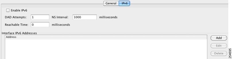
Step 2![]() In the IPv6 configuration area, check Enable IPv6 .
In the IPv6 configuration area, check Enable IPv6 .
This option enables IPv6 on all interfaces and automatically generates the link-local addresses using the Modified EUI-64 interface ID based on the interface MAC address.
Note You do not need to check this option if you configure any IPv6 addresses (either global or link-local); IPv6 support is automatically enabled as soon as you assign an IPv6 address. Similarly, unchecking this option does not disable IPv6 if you configured IPv6 addresses.
To configure IPv6 DAD parameters, shown in this area, see the “Configuring DAD Settings” section.
Configuring the Link-Local Address on an Interface Manually
If you only need to configure a link-local address and are not going to assign any other IPv6 addresses, you have the option of manually defining the link-local address.
Detailed Steps
Step 1![]() Choose the Configuration > Device Setup > Interfaces pane.
Choose the Configuration > Device Setup > Interfaces pane.
Step 2![]() Select an interface, and click Edit .
Select an interface, and click Edit .
The Edit Interface dialog box appears with the General tab selected.
Step 4![]() (Optional) To enforce the use of Modified EUI-64 format interface identifiers in IPv6 addresses on a local link, check the Enforce EUI-64 check box.
(Optional) To enforce the use of Modified EUI-64 format interface identifiers in IPv6 addresses on a local link, check the Enforce EUI-64 check box.
If the interface identifiers do not conform to the modified EUI-64 format, an error message appears. See the “Modified EUI-64 Interface IDs” section for more information.
Step 5![]() To set the link-local address, enter an address in the Link-local address field.
To set the link-local address, enter an address in the Link-local address field.
A link-local address should start with FE8, FE9, FEA, or FEB, for example fe80::20d:88ff:feee:6a82. See the “IPv6 Addresses” section for more information about IPv6 addressing.
Configuring DAD Settings
DAD verifies the uniqueness of new unicast IPv6 addresses before they are assigned and ensures that duplicate IPv6 addresses are detected in the network on a link basis.
For information about the Enable IPv6 parameter, see the “Configuring the Link-Local Addresses Automatically” section.
Detailed Steps
Step 1![]() Go to Configuration > Device Management > Management Access > Management IP Address.
Go to Configuration > Device Management > Management Access > Management IP Address.
Step 2![]() In the IPv6 configuration area, in the DAD attempts field, enter the number of allowed DAD attempts.
In the IPv6 configuration area, in the DAD attempts field, enter the number of allowed DAD attempts.
This setting configures the number of consecutive neighbor solicitation messages that are sent on an interface while DAD is performed on IPv6 addresses. Valid values are from 0 to 600. A zero value disables DAD processing on the specified interface. The default is one message.
Step 3![]() In the NS Interval field, enter the neighbor solicitation message interval.
In the NS Interval field, enter the neighbor solicitation message interval.
The neighbor solicitation message requests the link-layer address of a target node. Valid values are from 1000 to 3600000 milliseconds. The default is 1000 milliseconds.
Step 4![]() In the Reachable Time field, enter the amount of time in seconds that a remote IPv6 node is considered reachable after a leachability confirmation event has occurred.
In the Reachable Time field, enter the amount of time in seconds that a remote IPv6 node is considered reachable after a leachability confirmation event has occurred.
Valid values are from 1000 to 3600000 milliseconds. The default is zero. A configured time enables the detection of unavailable neighbors. Shorter times enable detection more quickly; however, very short configured times are not recommended in normal IPv6 operation.
Completing Interface Configuration in Transparent Mode (8.3 and Earlier)
This section includes tasks to complete the interface configuration for all models in transparent mode.
Note![]() For multiple context mode, complete the tasks in this section in the context execution space. In the Configuration > Device List pane, double-click the context name under the active device IP address.
For multiple context mode, complete the tasks in this section in the context execution space. In the Configuration > Device List pane, double-click the context name under the active device IP address.
This section includes the following topics:
- Task Flow for Completing Interface Configuration
- Configuring General Interface Parameters
- Configuring a Management Interface (ASA 5510 and Higher)
- Configuring the MAC Address, MTU, and TCP MSS
- Allowing Same Security Level Communication
Task Flow for Completing Interface Configuration
Step 1![]() Complete the procedures in the “Starting Interface Configuration (ASA 5510 and Higher)” section or the “Starting ASA 5505 Interface Configuration” section.
Complete the procedures in the “Starting Interface Configuration (ASA 5510 and Higher)” section or the “Starting ASA 5505 Interface Configuration” section.
Step 2![]() (Multiple context mode) In the Configuration > Device List pane, double-click the context name under the active device IP address.
(Multiple context mode) In the Configuration > Device List pane, double-click the context name under the active device IP address.
Step 3![]() Configure general interface parameters, including the interface name and security level. See the “Configuring General Interface Parameters” section.
Configure general interface parameters, including the interface name and security level. See the “Configuring General Interface Parameters” section.
Step 4![]() (Optional) Configure a management interface. See the “Configuring a Management Interface (ASA 5510 and Higher)” section.
(Optional) Configure a management interface. See the “Configuring a Management Interface (ASA 5510 and Higher)” section.
Step 5![]() (Optional) Configure the MAC address and the MTU. See the “Configuring the MAC Address, MTU, and TCP MSS” section.
(Optional) Configure the MAC address and the MTU. See the “Configuring the MAC Address, MTU, and TCP MSS” section.
Step 6![]() (Optional) Allow same security level communication, either by allowing communication between two interfaces or by allowing traffic to enter and exit the same interface. See the “Allowing Same Security Level Communication” section.
(Optional) Allow same security level communication, either by allowing communication between two interfaces or by allowing traffic to enter and exit the same interface. See the “Allowing Same Security Level Communication” section.
Configuring General Interface Parameters
This procedure describes how to set the name, security level, and bridge group for each transparent interface.
To configure a separate management interface, see the “Configuring a Management Interface (ASA 5510 and Higher)” section.
For the ASA 5510 and higher, you must configure interface parameters for the following interface types:
For the ASA 5505, you must configure interface parameters for the following interface types:
Guidelines and Limitations
- You can configure up to two interfaces per context.
- For the ASA 5550 ASA, for maximum throughput, be sure to balance your traffic over the two interface slots; for example, assign the inside interface to slot 1 and the outside interface to slot 0.
- For information about security levels, see the “Security Levels” section.
- If you are using failover, do not use this procedure to name interfaces that you are reserving for failover and Stateful Failover communications. See “Configuring Failover,” to configure the failover and state links.
Prerequisites
- Complete the procedures in “Starting Interface Configuration (ASA 5510 and Higher),” or Chapter12, “Starting Interface Configuration (ASA 5505)”
- In multiple context mode, complete this procedure in the context execution space. To change from the system to a context configuration, in the Configuration > Device List pane, double-click the context name under the active device IP address.
Detailed Steps
Step 1![]() Choose the Configuration > Device Setup > Interfaces pane.
Choose the Configuration > Device Setup > Interfaces pane.
In multiple context mode, only interfaces that were assigned to the context in the System execution space appear in the table.
Step 2![]() Choose the row for an interface, and click Edit .
Choose the row for an interface, and click Edit .
The Edit Interface dialog box appears with the General tab selected.
Step 3![]() In the Interface Name field, enter a name up to 48 characters in length.
In the Interface Name field, enter a name up to 48 characters in length.
Step 4![]() In the Security level field, enter a level between 0 (lowest) and 100 (highest).
In the Security level field, enter a level between 0 (lowest) and 100 (highest).
See the “Security Levels” section for more information.
Step 5![]() If the interface is not already enabled, check the Enable Interface check box.
If the interface is not already enabled, check the Enable Interface check box.
Step 6![]() (Optional) In the Description field, enter a description for this interface.
(Optional) In the Description field, enter a description for this interface.
The description can be up to 240 characters on a single line, without carriage returns. In the case of a failover or state link, the description is fixed as “LAN Failover Interface,” “STATE Failover Interface,” or “LAN/STATE Failover Interface,” for example. You cannot edit this description. The fixed description overwrites any description you enter here if you make this interface a failover or state link.
Note (ASA 5510 and higher, single mode) For information about the Configure Hardware Properties button, see the “Enabling the Physical Interface and Configuring Ethernet Parameters” section.
What to Do Next
- (Optional) Configure a management interface. See the “Configuring a Management Interface (ASA 5510 and Higher)” section.
- (Optional) Configure the MAC address and the MTU. See the “Configuring the MAC Address, MTU, and TCP MSS” section.
Configuring a Management Interface (ASA 5510 and Higher)
You can configure one management interface separate from the network interfaces in single mode or per context. You can use the Management slot / port interface (either the physical interface or a subinterface) as a separate management interface. You cannot use any other interface type as a management interface. For more information, see the “Management Interface” section.
Configuring General Parameters and the IPv4 Address
This section describes how to configure the name, security level, and IPv4 address for a management interface.
Prerequisites
- Complete the procedures in “Starting Interface Configuration (ASA 5510 and Higher),” or Chapter12, “Starting Interface Configuration (ASA 5505)”
- In multiple context mode, complete this procedure in the context execution space. To change from the system to a context configuration, in the Configuration > Device List pane, double-click the context name under the active device IP address.
Detailed Steps
Step 1![]() Choose the Configuration > Device Setup > Interfaces pane.
Choose the Configuration > Device Setup > Interfaces pane.
In multiple context mode, only interfaces that were assigned to the context in the System execution space appear in the table.
Step 2![]() Choose the row for a Management interface or subinterface and click Edit .
Choose the row for a Management interface or subinterface and click Edit .
The Edit Interface dialog box appears with the General tab selected.
Step 3![]() In the Interface Name field, enter a name up to 48 characters in length.
In the Interface Name field, enter a name up to 48 characters in length.
Step 4![]() In the Security level field, enter a level between 0 (lowest) and 100 (highest).
In the Security level field, enter a level between 0 (lowest) and 100 (highest).
See the “Security Levels” section for more information.
Note The Dedicate this interface to management only check box is enabled by default and is non-configurable.
Step 5![]() If the interface is not already enabled, check the Enable Interface check box.
If the interface is not already enabled, check the Enable Interface check box.
Step 6![]() To set the IP address, use one of the following options.
To set the IP address, use one of the following options.
Note For use with failover, you must set the IP address and standby address manually; DHCP is not supported. Set the standby IP addresses on the Configuration > Device Management > High Availability > Failover > Interfaces tab.

a.![]() To force a MAC address to be stored inside a DHCP request packet for option 61, click the Use MAC Address radio button.
To force a MAC address to be stored inside a DHCP request packet for option 61, click the Use MAC Address radio button.
Some ISPs expect option 61 to be the interface MAC address. If the MAC address is not included in the DHCP request packet, then an IP address will not be assigned.
b.![]() To use a generated string for option 61, click Use “Cisco-<MAC>-<interface_name>-<host>” .
To use a generated string for option 61, click Use “Cisco-<MAC>-<interface_name>-<host>” .
c.![]() (Optional) To obtain the default route from the DHCP server, check Obtain Default Route Using DHCP .
(Optional) To obtain the default route from the DHCP server, check Obtain Default Route Using DHCP .
d.![]() (Optional) To set the broadcast flag to 1 in the DHCP packet header when the DHCP client sends a discover requesting an IP address, check Enable DHCP Broadcast flag for DHCP request and discover messages .
(Optional) To set the broadcast flag to 1 in the DHCP packet header when the DHCP client sends a discover requesting an IP address, check Enable DHCP Broadcast flag for DHCP request and discover messages .
The DHCP server listens to this broadcast flag and broadcasts the reply packet if the flag is set to 1.
e.![]() (Optional) To renew the lease, click Renew DHCP Lease .
(Optional) To renew the lease, click Renew DHCP Lease .
Step 7![]() (Optional) In the Description field, enter a description for this interface.
(Optional) In the Description field, enter a description for this interface.
The description can be up to 240 characters on a single line, without carriage returns.
Note (ASA 5510 and higher, single mode) For information about the Configure Hardware Properties button, see the “Enabling the Physical Interface and Configuring Ethernet Parameters” section.
Configuring a Global IPv6 Address and Other Options
To configure a global IPv6 address and other options for the management interface, perform the following steps.
Note![]() Configuring the global address automatically configures the link-local address, so you do not need to configure it separately.
Configuring the global address automatically configures the link-local address, so you do not need to configure it separately.
Restrictions
Prerequisites
- Complete the procedures in “Starting Interface Configuration (ASA 5510 and Higher),” or Chapter12, “Starting Interface Configuration (ASA 5505)”
- In multiple context mode, complete this procedure in the context execution space. To change from the system to a context configuration, in the Configuration > Device List pane, double-click the context name under the active device IP address.
Detailed Steps
Step 1![]() Choose the Configuration > Device Setup > Interfaces pane.
Choose the Configuration > Device Setup > Interfaces pane.
Step 2![]() Choose a management interface, and click Edit .
Choose a management interface, and click Edit .
The Edit Interface dialog box appears with the General tab selected.
Step 4![]() (Optional) To enforce the use of Modified EUI-64 format interface identifiers in IPv6 addresses on a local link, check the Enforce EUI-64 check box.
(Optional) To enforce the use of Modified EUI-64 format interface identifiers in IPv6 addresses on a local link, check the Enforce EUI-64 check box.
See the “Modified EUI-64 Interface IDs” section for more information.
Step 5![]() To configure the global IPv6 address:
To configure the global IPv6 address:
a.![]() In the Interface IPv6 Addresses area, click Add .
In the Interface IPv6 Addresses area, click Add .
The Add IPv6 Address for Interface dialog box appears.
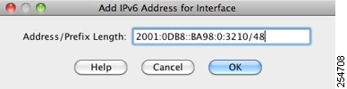
b.![]() In the Address/Prefix Length field, enter the global IPv6 address and the IPv6 prefix length. For example, 2001:0DB8::BA98:0:3210/48. See the “IPv6 Addresses” section for more information about IPv6 addressing.
In the Address/Prefix Length field, enter the global IPv6 address and the IPv6 prefix length. For example, 2001:0DB8::BA98:0:3210/48. See the “IPv6 Addresses” section for more information about IPv6 addressing.
Step 6![]() (Optional) In the top area, customize the IPv6 configuration by configuring the following options:
(Optional) In the top area, customize the IPv6 configuration by configuring the following options:
- DAD Attempts—This setting configures the number of consecutive neighbor solicitation messages that are sent on an interface while DAD is performed on IPv6 addresses. Valid values are from 0 to 600. A zero value disables DAD processing on the specified interface. The default is one message.
- NS Interval—Enter the neighbor solicitation message interval. The neighbor solicitation message requests the link-layer address of a target node. Valid values are from 1000 to 3600000 milliseconds. The default is 1000 milliseconds.
- Reachable Time—Enter the amount of time in seconds that a remote IPv6 node is considered reachable after a reachability confirmation event has occurred. Valid values are from 0 to 3600000 milliseconds. The default is zero. A configured time enables the detection of unavailable neighbors. Shorter times enable detection more quickly; however, very short configured times are not recommended in normal IPv6 operation.
You return to the Configuration > Device Setup > Interfaces pane.
What to Do Next
(Optional) Configure the MAC address and the MTU. See the “Configuring the MAC Address, MTU, and TCP MSS” section.
Configuring the MAC Address, MTU, and TCP MSS
This section describes how to configure MAC addresses for interfaces, how to set the MTU, and set the TCP MSS.
Information About MAC Addresses
By default, the physical interface uses the burned-in MAC address, and all subinterfaces of a physical interface use the same burned-in MAC address.
A redundant interface uses the MAC address of the first physical interface that you add. If you change the order of the member interfaces in the configuration, then the MAC address changes to match the MAC address of the interface that is now listed first. If you assign a MAC address to the redundant interface using this command, then it is used regardless of the member interface MAC addresses.
For an EtherChannel, all interfaces that are part of the channel group share the same MAC address. This feature makes the EtherChannel transparent to network applications and users, because they only see the one logical connection; they have no knowledge of the individual links. The port-channel interface uses the lowest numbered channel group interface MAC address as the port-channel MAC address. Alternatively you can manually configure a MAC address for the port-channel interface. In multiple context mode, you can automatically assign unique MAC addresses to interfaces, including an EtherChannel port interface. We recommend manually, or in multiple context mode, automatically configuring a unique MAC address in case the group channel interface membership changes. If you remove the interface that was providing the port-channel MAC address, then the port-channel MAC address changes to the next lowest numbered interface, thus causing traffic disruption.
In multiple context mode, if you share an interface between contexts, you can assign a unique MAC address to the interface in each context. This feature lets the ASA easily classify packets into the appropriate context. Using a shared interface without unique MAC addresses is possible, but has some limitations. See the “How the ASA Classifies Packets” section for more information. You can assign each MAC address manually, or you can automatically generate MAC addresses for shared interfaces in contexts. See the “Automatically Assigning MAC Addresses to Context Interfaces” section to automatically generate MAC addresses. If you automatically generate MAC addresses, you can use this procedure to override the generated address.
For single context mode, or for interfaces that are not shared in multiple context mode, you might want to assign unique MAC addresses to subinterfaces. For example, your service provider might perform access control based on the MAC address.
Information About the MTU and TCP MSS
See the “Controlling Fragmentation with the Maximum Transmission Unit and TCP Maximum Segment Size” section.
Prerequisites
- Complete the procedures in “Starting Interface Configuration (ASA 5510 and Higher),” or Chapter12, “Starting Interface Configuration (ASA 5505)”
- In multiple context mode, complete this procedure in the context execution space. To change from the system to a context configuration, in the Configuration > Device List pane, double-click the context name under the active device IP address.
Detailed Steps
Step 1![]() Choose the Configuration > Device Setup > Interfaces pane.
Choose the Configuration > Device Setup > Interfaces pane.
BVIs appear in the table alongside physical interfaces, subinterfaces, redundant interfaces, and EtherChannel port-channel interfaces. In multiple context mode, only interfaces that were assigned to the context in the System execution space appear in the table.
Step 2![]() Choose the row for a physical interface, subinterface, redundant interface, or EtherChannel port-interface, and click Edit .
Choose the row for a physical interface, subinterface, redundant interface, or EtherChannel port-interface, and click Edit .
The Edit Interface dialog box appears with the General tab selected.
Step 3![]() Click the Advanced tab.
Click the Advanced tab.

Step 4![]() To set the MTU or to enable jumbo frame support (supported models), enter the value in the MTU field, between 300 and 65,535 bytes.
To set the MTU or to enable jumbo frame support (supported models), enter the value in the MTU field, between 300 and 65,535 bytes.
Note When you set the MTU for a redundant or port-channel interface, the ASA applies the setting to all member interfaces.
- For models that support jumbo frames in single mode—If you enter a value for any interface that is greater than 1500, then you enable jumbo frame support automatically for all interfaces. If you set the MTU for all interfaces back to a value under 1500, then jumbo frame support is disabled.
- For models that support jumbo frames in multiple mode—If you enter a value for any interface that is greater than 1500, then be sure to enable jumbo frame support in the system configuration. See the “Enabling Jumbo Frame Support (Supported Models)” section.
Note![]() Enabling or disabling jumbo frame support requires you to reboot the ASA.
Enabling or disabling jumbo frame support requires you to reboot the ASA.
A jumbo frame is an Ethernet packet larger than the standard maximum of 1518 bytes (including Layer 2 header and FCS), up to 9216 bytes. Jumbo frames require extra memory to process, and assigning more memory for jumbo frames might limit the maximum use of other features, such as ACLs.
Step 5![]() To manually assign a MAC address to this interface, enter a MAC address in the Active Mac Address field in H.H.H format, where H is a 16-bit hexadecimal digit.
To manually assign a MAC address to this interface, enter a MAC address in the Active Mac Address field in H.H.H format, where H is a 16-bit hexadecimal digit.
For example, the MAC address 00-0C-F1-42-4C-DE would be entered as 000C.F142.4CDE. The first two bytes of a manual MAC address cannot be A2 if you also want to use auto-generated MAC addresses.
Step 6![]() If you use failover, enter the standby MAC address in the Standby Mac Address field. If the active unit fails over and the standby unit becomes active, the new active unit starts using the active MAC addresses to minimize network disruption, while the old active unit uses the standby address.
If you use failover, enter the standby MAC address in the Standby Mac Address field. If the active unit fails over and the standby unit becomes active, the new active unit starts using the active MAC addresses to minimize network disruption, while the old active unit uses the standby address.
Step 7![]() To set the TCP MSS, choose Configuration > Firewall > Advanced > TCP Options . Set the following options:
To set the TCP MSS, choose Configuration > Firewall > Advanced > TCP Options . Set the following options:
- Force Maximum Segment Size for TCP—Sets the maximum TCP segment size in bytes, between 48 and any maximum number. The default value is 1380 bytes. You can disable this feature by setting the bytes to 0.
- Force Minimum Segment Size for TCP — Overrides the maximum segment size to be no less than the number of bytes you set, between 48 and any maximum number. This feature is disabled by default (set to 0).
Allowing Same Security Level Communication
By default, interfaces on the same security level cannot communicate with each other, and packets cannot enter and exit the same interface. This section describes how to enable inter-interface communication when interfaces are on the same security level.
Information About Inter-Interface Communication
Allowing interfaces on the same security level to communicate with each other is useful if you want traffic to flow freely between all same security interfaces without ACLs.
If you enable same security interface communication, you can still configure interfaces at different security levels as usual.
Detailed Steps
To enable interfaces on the same security level to communicate with each other, from the Configuration > Interfaces pane, check Enable traffic between two or more interfaces which are configured with same security level .
Monitoring Interfaces
For information about monitoring screens, see the “Monitoring Interfaces” section.
Feature History for Interfaces in Transparent Mode
Table 15-1 lists each feature change and the platform release in which it was implemented. ASDM is backwards-compatible with multiple platform releases, so the specific ASDM release in which support was added is not listed.
|
|
|
|
|---|---|---|
The maximum number of VLANs for the Security Plus license on the ASA 5505 ASA was increased from 5 (3 fully functional; 1 failover; one restricted to a backup interface) to 20 fully functional interfaces. In addition, the number of trunk ports was increased from 1 to 8. Now there are 20 fully functional interfaces, you do not need to use the backup interface command to cripple a backup ISP interface; you can use a fully-functional interface for it. The backup interface command is still useful for an Easy VPN configuration. VLAN limits were also increased for the ASA 5510 ASA (from 10 to 50 for the Base license, and from 25 to 100 for the Security Plus license), the ASA 5520 ASA (from 100 to 150), the ASA 5550 ASA (from 200 to 250). |
||
Gigabit Ethernet Support for the ASA 5510 Security Plus License |
The ASA 5510 ASA now supports GE (Gigabit Ethernet) for port 0 and 1 with the Security Plus license. If you upgrade the license from Base to Security Plus, the capacity of the external Ethernet0/0 and Ethernet0/1 ports increases from the original FE (Fast Ethernet) (100 Mbps) to GE (1000 Mbps). The interface names will remain Ethernet 0/0 and Ethernet 0/1. |
|
You can now include the native VLAN in an ASA 5505 trunk port. We modified the following screen: Configuration > Device Setup > Interfaces > Switch Ports > Edit Switch Port. |
||
The Cisco ASA 5580 supports jumbo frames. A jumbo frame is an Ethernet packet larger than the standard maximum of 1518 bytes (including Layer 2 header and FCS), up to 9216 bytes. You can enable support for jumbo frames for all interfaces by increasing the amount of memory to process Ethernet frames. Assigning more memory for jumbo frames might limit the maximum use of other features, such as ACLs. We modified the following screen: Configuration > Device Setup > Interfaces > Add/Edit Interface > Advanced. |
||
The number of VLANs supported on the ASA 5580 are increased from 100 to 250. |
||
Support for Pause Frames for Flow Control on the ASA 5580 10-Gigabit Ethernet Interfaces |
You can now enable pause (XOFF) frames for flow control. We modified the following screens: |
|
Bridge groups for transparent mode (see Chapter14, “Completing Interface Configuration (Transparent Mode, 8.4 and Later)”) |
If you do not want the overhead of security contexts, or want to maximize your use of security contexts, you can group interfaces together in a bridge group, and then configure multiple bridge groups, one for each network. Bridge group traffic is isolated from other bridge groups. You can configure up to eight bridge groups of four interfaces each in single mode or per context. We modified or introduced the following screens: |
 Feedback