Overview
Objective
Network operators need a toolset to help automate bandwidth optimization, steer traffic with little operator intervention, and ensure that critical links always have sufficient bandwidth to avoid congestion.
Challenge
For service providers, managing bandwidth problems used to be a reactive and manual process. Pressure to solve it is huge. Network congestion leads to poor end-customer experiences. Congested links, high latency, and other network impairments lead to a poor perception of the services carried across your network or result in an inability to meet the service level agreements (SLAs) you have with your customers. In the worst-case scenario, your network issues lead to SLA or contract violations and the loss of your brand equity.
Solution
Using LCM and Circuit Style policies, SPs can now specify business-critical links with the intention to reserve bandwidth for these links. Identifying critical links and the operator's intention enables automatic optimization of the network in real time.
Cisco Crosswork Network Controller offers both:
-
Local Congestion Mitigation (LCM) is a tactical solution for bandwidth management and congestion mitigation. It is best applied when you are attempting to solve congestion issues directly, on the devices themselves, without a full-scale traffic matrix or advanced planning.
-
Circuit-Style Segment Routing (CS-SR) is a strategic traffic engineering solution that permits you to reserve bandwidth in advance for critical links, avoiding congestion issues entirely for these high-priority links.
Local Congestion Mitigation (LCM)
Instead of optimizing for bandwidth resource in the network by rerouting traffic in the entire network (end-to-end path optimization), LCM checks the capacity locally, in and around the congested area, at an interface level and reroutes traffic between the endpoints of the congested interface (local interface-level optimization). Focusing on an issue locally eliminates the need for simulating edge-to-edge traffic flows in the network through a full traffic matrix, which is both cumbersome to create and is less scalable as node counts continue to increase.
When congestion is detected in the network, LCM provides recommendations to divert the minimum amount of traffic away from the congested interface. LCM performs the collection of SR-TE policy and interface counters through SNMP. It estimates the amount of traffic that may be diverted and, if the user approves, performs the mitigation through the deployment of Tactical Traffic Engineering (TTE) SR-TE policies. Mitigating congestion locally does not require the use of the full Segment Routing Traffic Matrix (SR-TM). TTE SR-TE policies are created at the device on only either side of the congested link, with the shortest paths possible that do not congest interfaces elsewhere.
How Does LCM Work?
-
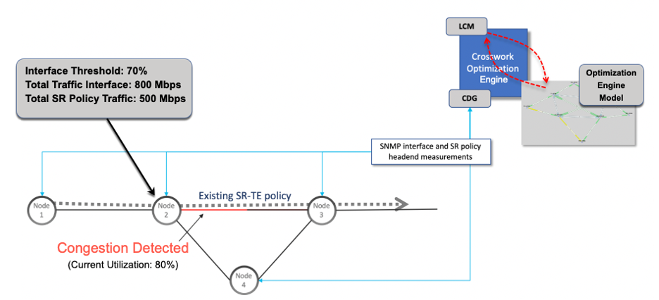
First, network operators creates domains that define "local" portions of the network. A domain can be the entire network, but more commonly a domain will match one or geographical areas or groups of device interfaces. In this example, we have defined a domain with four devices and all their interfaces. We also assume that all the links in this domain are 1Gpbs.
-
Operator specifies a threshold defining what "congestion" means for a particular domain. In this example, the operator has set the domain's congestion threshold to 70%. The congestion threshold you decide on may vary. For guidance on how to determine what's congestion threshold is best for your network and its domain architecture, see Cisco's Local Congestion Mitigation (LCM) White Paper.
-
LCM first analyzes the Optimization Engine Model (a realtime representation of the physical network, its topology and its traffic) on a regular cadence. After a congestion check interval, LCM detects congestion when Node 2 utilization goes above the 70% utilization threshold.
-
LCM calculates how much traffic is eligible to divert. LCM will follow these rules and restrictions in its recommendations:
LCM only diverts traffic that is not already routed by an existing SR policy (for example: unlabeled, IGP-routed, or carried via FlexAlgo-0 SIDs). The traffic within an SR policy will not be included in LCM calculation and will continue to travel over the original programmed path.
LCM computes diversion-eligible traffic by taking the interface traffic statistics that account for all traffic on the interface and subtracting the sum of traffic statistics for all SR-TE policies that flow over the interface.
Total interface traffic – SR policy traffic = Eligible traffic that can be optimized
This process must account for any ECMP splitting of SR policies to ensure the proper accounting of SR policy traffic. In this example, the total traffic on congested Node 2 is 800 Mbps. The total traffic of all SR policies routed over Node 2 is 500 Mbps.
The total traffic that LCM can divert in this example is 240 Mbps. That is: 800 Mbps – 560 Mbps = 240 Mbps
-
LCM calculates the amount of traffic that must be sent over alternate paths by subtracting the threshold-equivalent traffic from the total traffic on the interface. In this example, the amount to be diverted is 100 Mbps:
800 Mbps – 640 Mbps (70% threshold) = 100 Mbps
LCM must route 100 Mbps of 300 Mbps (eligible traffic) to another path.
-
LCM determines how many TTE SR policies are needed and their paths. The ratio of how much LCM eligible traffic can stay on the shortest path to the amount that must be rerouted, will determine the number of TTE SR policies that are needed on the shortest versus alternate paths, respectively.
In this example, LCM needs to divert one-third of the total eligible traffic (100 Mbps out of 300 Mbps) away from the congested link. Assuming a perfect ECMP, LCM estimates that three tactical SR-TE policies are required to create this traffic split: one tactical SR-TE policy will take the diversion path and two tactical SR-TE policies will take the original path. There is sufficient capacity in the path between Node 2 and Node 4. Therefore, LCM recommends three TTE SR policies (each expected to route approximately 100 Mbps) to be deployed from Node 2 to Node 3 via SR-PCE:
-
2 TTE SR policies to take a direct path to Node 3 (200 Mbps)
-
1 TTE SR policy takes a path via Node 4 (100 Mbps)
These recommendations will be listed in the LCM Operational Dashboard.
-
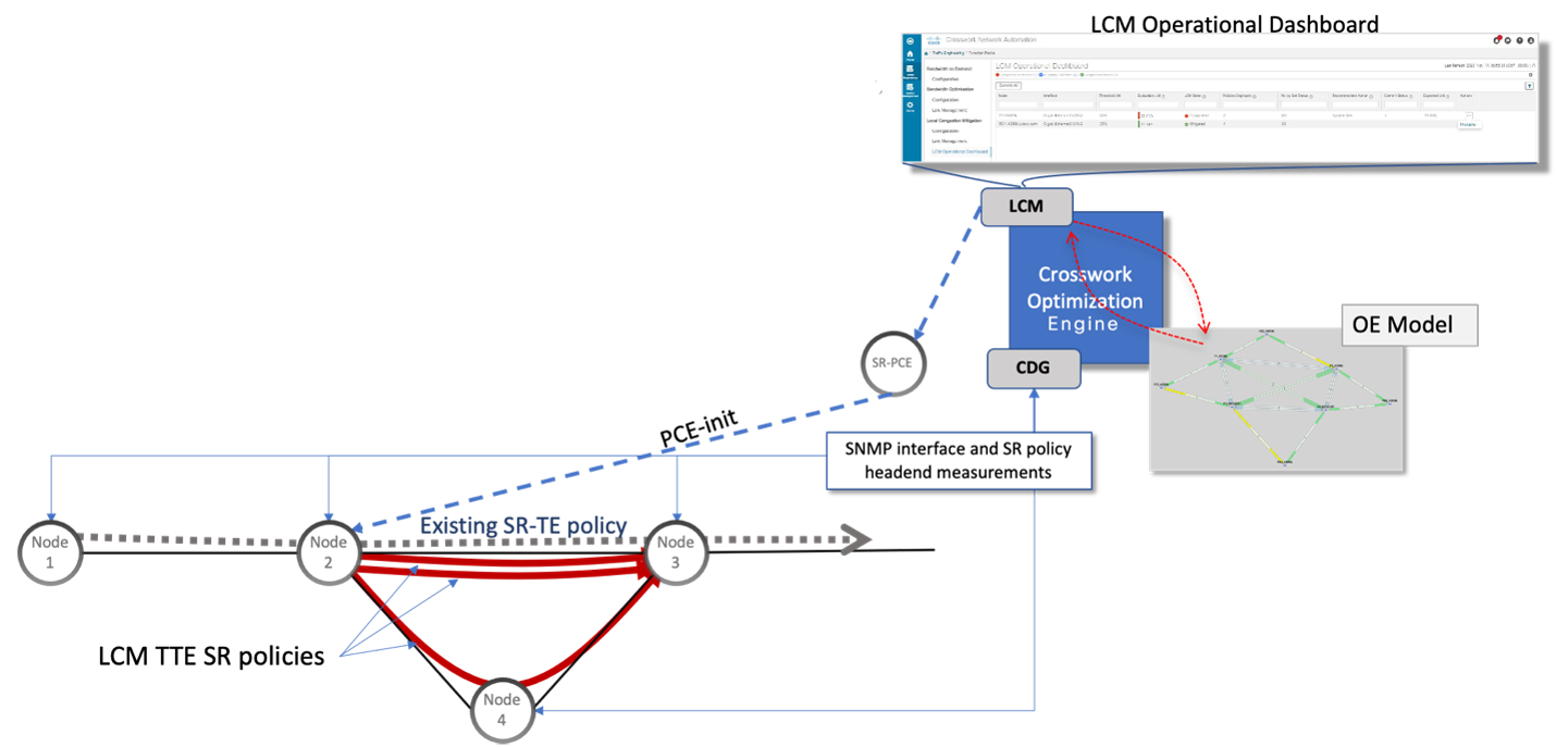
Assuming you deploy these TTE SR policies, LCM continues to monitor the deployed TTE policies and will recommend modifications or deletions as needed in the LCM Operational Dashboard. TTE SR policy removal recommendations will occur if the mitigated interface would not be congested if these policies were removed (minus a hold margin). This helps to avoid unnecessary TTE SR policy churn throughout the LCM operation.
Circuit-Style Policies
Circuit-Style Segment Routing Policies (CS-SR, or CS policies) are connection-oriented transport services that you can use to implement what are sometimes referred to as "circuit emulations" or "private lines". Combining segment-routing architecture's adjacency SIDs with stateful PCEP path computation, CS policies provide:
-
Persistent, dedicated, bi-directional, co-routed transport paths with predictable latencies and other performance metrics in both directions.
-
Guaranteed bandwidth commitments for traffic-engineered services using these paths.
-
End-to-end path protection to ensure there is no impact on Service Level Agreements.
-
Automatic monitoring, maintenance and restoration of path integrity.
-
Flexible operations, administration and management of Circuit-Style paths.
-
A software-defined replacement for older CEM infrastructure, such as SONET/SDH.
How Do Circuit-Style Policies Work?
Initial configuration of CS policies follows these steps:
-
Crosswork Network Controller and its applications discover and map the network topology.
-
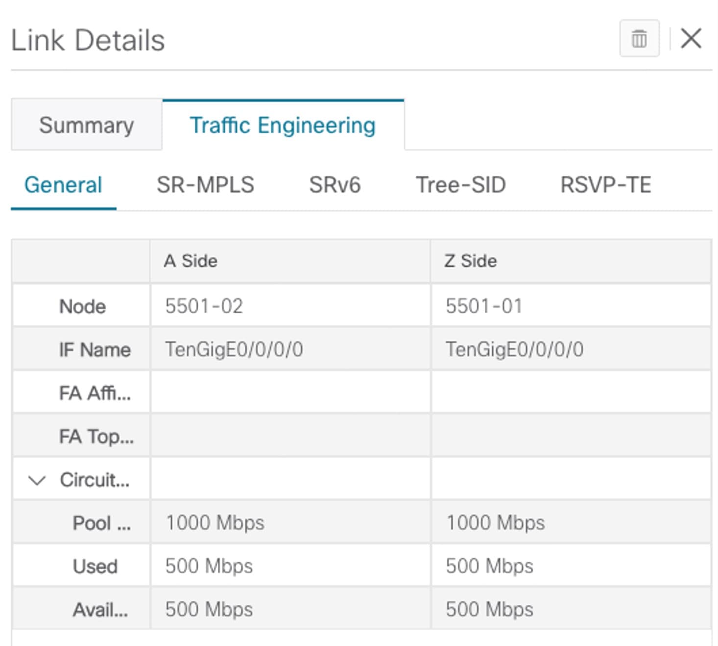
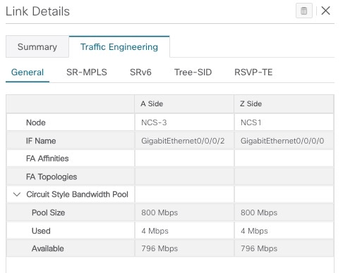
Crosswork users enable CS policy support, specifying the base bandwidth to be allocated to CS policies as a whole, and a threshold percentage of bandwidth usage which, when exceeded on any CS-calculated path, will generate an alarm. So, for example, on a 1 GB link with 20 percent of bandwidth reserved for Circuit Style use, CS policies can use up to 200 Mbps of that link. Note, however, that if the bandwidth minimum threshold is set to the default of 80 percent, alarms will be generated as soon as 160 Mbps of the link is used.
-
Network operators create a CS policy for each set of nodes for which they want to establish a guaranteed path. The policy specifies the two nodes to be linked by the main path, the bandwidth to be reserved, and the backup path. To ensure bandwidth and path failures can be accommodated, the configuration must include bi-directionality, path protection, and performance-management liveness-detection settings.
-
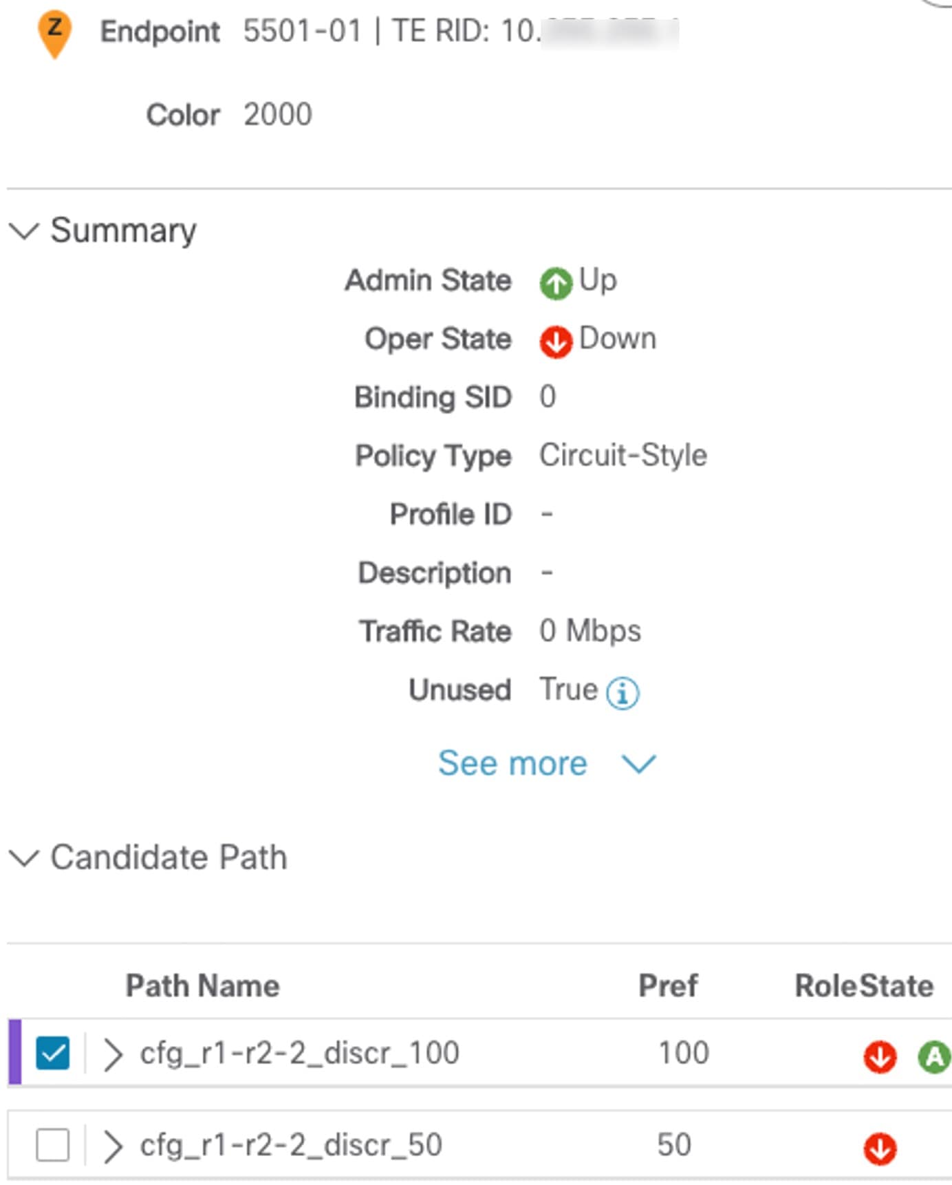
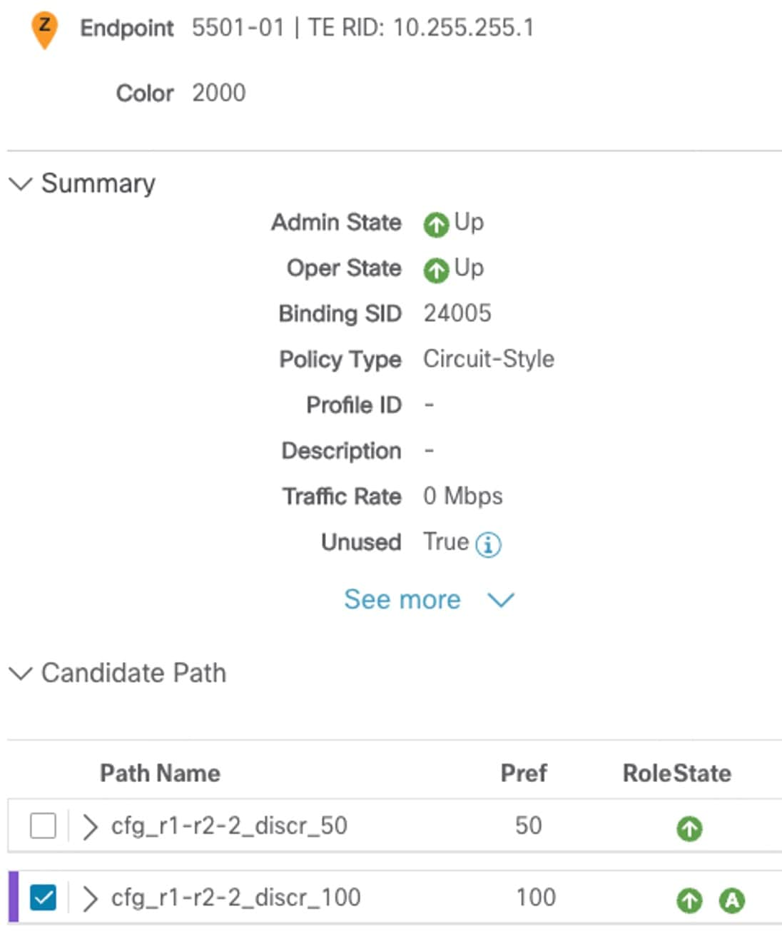
When the operator commits the CS policy, the device-resident Path Computation Client (PCC) will request the Crosswork-resident PCE server to compute candidate Working and Protected paths that conform to the CS policy's bandwidth and other constraints (using a single PCEP request message).
-
The PCC computes both paths and deducts the CS policy-guaranteed bandwidth for them from the total available bandwidth allocated when CS policy support was enabled.
-
Crosswork replies to the PCC with the primary Working and Protected path lists and commits to, or "delegates", them. The topology map displays the current Active and Protected paths between the two nodes, using the colors configured when the CS policy was configured, and labels the two endpoint nodes so they can be identified as CS policy endpoints.
After the initial configuration:
-
Crosswork monitors the delegated path and the active CS policies. It updates the available and reservable bandwidth in the network in near real time.
-
Crosswork generates threshold-crossing alarms when bandwidth usage or additional CS policy requirements exceed the configured reserved bandwidth or bandwidth usage threshold.
-
If delegated paths fail for any reason, Crosswork recomputes paths as needed.
Scenario: Use LCM to Reroute Traffic on an Overused Link
In this scenario, we will enable Local Congestion Mitigation (LCM) and observe its congestion mitigation recommendations. LCM will recommend that we deploy Tactical Traffic Engineering Segment Routing (TTE SR) policies on a device’s interfaces when usage exceeds a defined threshold. We will preview the recommended TTE SR policies before committing them.
 Note |
If you are viewing the HTML version of this guide, click on the images to view them in full-size. |
We will enable LCM with a configuration that results in the link between cw-xrv60 and cw-xrv60 becoming over-used. We will then review the mitigation solutions Crosswork calculates. In this example, it is left to the operator whether to apply the solution or not.
LCM Scenario: Assumptions and Prerequisites
The following sections list high-level requirements that must be met to ensure proper LCM operation.
Congestion Evaluation Requirements
LCM requires traffic statistics from the following:
-
Interface traffic measurements
-
Headend SR-TE policy traffic measurements
To ensure LCM is receiving these traffic statistics:
-
Enable SNMP on the devices whose traffic you want to monitor, including the headend device. For more on this task, see Configuring SNMP Support. Note that gNMI is also an option for collecting traffic measurements.
-
Ensure that the SNMP-enabled devices are all reachable from the Crosswork Data Gateway. For more on this task, see Check Connectivity to the Destination.
-
Configure the headend device to use strict SID labels for SR policies. To perform this task:
-
Enable segment routing on the headend device and configure the segment routing global block (SRGB) and the segment routing local block (SRLB) ranges. For example: segment-routing mpls global-block 16000 23999 node-msd 16 ! srlb 15000 15999 -
Configure the SR policy candidate paths to use strict SID labels. You can use either explicit paths or dynamic paths with constraints. For example: segment-routing traffic-eng policy COLOR-100-TO-10.0.0.1 color 100 end-point ipv4 10.0.0.1 candidate-paths preference 100 explicit segment-list SL1 ! preference 200 dynamic constraints affinity include-any RED BLUE sid-algorithm strict-spf ! ! ! ! ! ! ! segment-list SL1 index 10 mpls label 16001 node 10.0.0.2 strict index 20 mpls label 16002 node 10.0.0.3 strict index 30 mpls label 16003 node 10.0.0.4 strict ! -
Configure the SR policy headend behavior using the binding SID and the autoroute announce option. For example: !segment-routing traffic-eng pcc profile 1 autoroute include ipv4 all force-sr-include ! ! ! !
-
Congestion Mitigation Requirements
The headend device must support PCE-initiated SR-TE policies with autoroute steering. However, LCM will not work if the headend is a Cisco NCS device and there is L2VPN traffic in the network.
force-sr-include to enable traffic steering into SR-TE policies with autoroute. For example: segment-routing traffic-eng pcc profile ID autoroute force-sr-includeThe ID parameter in this command identifies the PCC profile associated with the SR-TE policy that PCE has provisioned. The ID value
can be any integer from 1 to 65535, but it must match the profile ID that PCE uses to instantiate the policy. If not, the
policy will not be activated. For example, if PCE provisions a policy with profile ID 10, you must configure segment-routing traffic-eng pcc profile 10 autoroute force-sr-include on the headend router to enable autoroute announcement for that policy. For more information, see the Segment Routing Configuration Guide, Cisco IOS XE 17 (Cisco ASR 920 Series), COE-PCE Initiated SR Policy with OSPF and IS-IS SR-TE Autoroute Announce.
Note |
The ID that is configured under the PCC profile, must match the Profile ID option set in the LCM Configuration page. |
The headend device must support Equal Cost Multi-Path (ECMP) across multiple parallel SR-TE policies. To verify that a device can support SR-TE policies using ECMP, check that the device has the following:
-
Segment Routing is enabled and configured, with a Segment Routing Global Block (SRGB) that matches the SRGB of the SR-TE policy headend and tailend routers. Use the
show segment-routing mpls statecommand to verify the SRGB configuration on the device. -
BGP-LS is enabled and configured to advertise and receive link-state information from the SR-TE policy headend and tailend routers. Use the
show bgp link-state link-statecommand to verify the BGP-LS status and theshow bgp link-state link-state databasecommand to verify the link-state information on the device. -
ECMP is enabled and configured to load-balance traffic across multiple equal-cost paths based on flows. Use the
show ip routecommand to verify the ECMP routes and theshow ip cefcommand to verify the ECMP load-balancing algorithm on the device.
If all these conditions are met, then the device can support an SR-TE policy using ECMP.
Related Topics
For more information and examples on how to configure and verify SR-TE policies, see:
LCM Scenario: Workflow
|
Workflow steps |
Detailed procedure links |
|---|---|
|
Step 1. Enable LCM and configure the global utilization thresholds |
Step 1: Enable LCM and Configure the Utilization Thresholds |
|
Step 2. View link congestion on the map |
Step 2: View Link Congestion on the Map |
|
Step 3. View TTE SR policy recommendations in the LCM Operational Dashboard |
Step 3: View TTE SR Policy Recommendations in the LCM Operational Dashboard |
|
Step 4. Validate the TTE SR policy deployment |
Step 4: Validate TTE SR Policy Deployment |
|
Step 5. Remove the TTE SR policies upon LCM recommendation |
Step 5: Remove TTE SR policies on LCM Recommendation |
Step 1: Enable LCM and Configure the Utilization Thresholds
To enable LCM and configure the global utilization threshold:
Procedure
|
Step 1 |
Go to Services & Traffic Engineering > Local Congestion Mitigation > Domain-ID and click Configure. |
||
|
Step 2 |
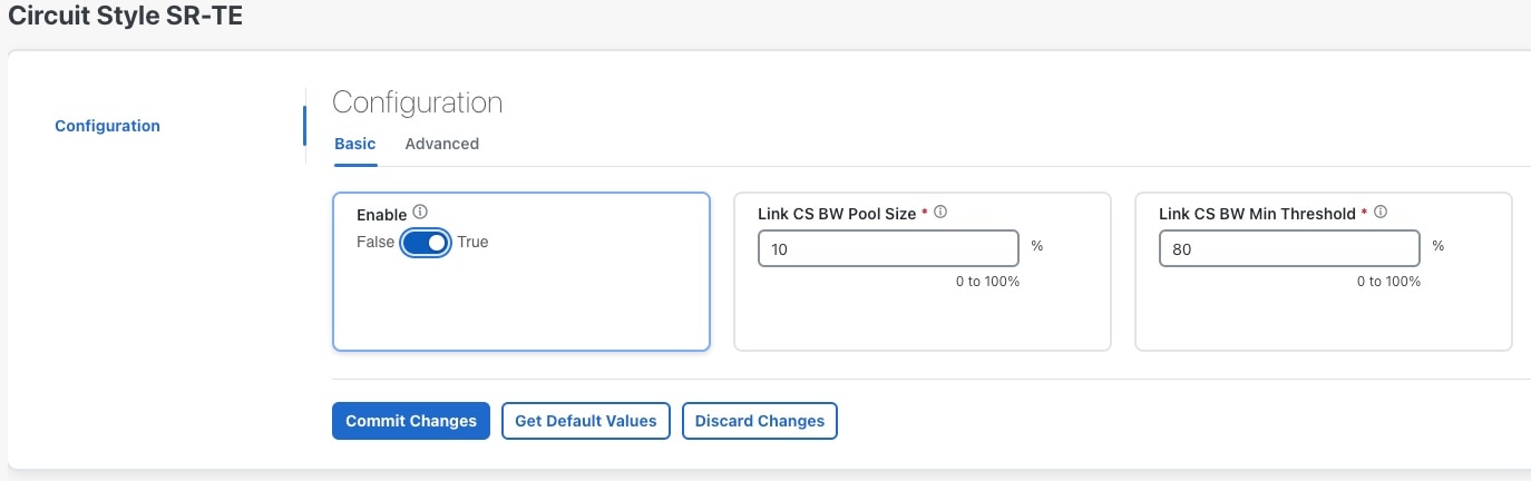
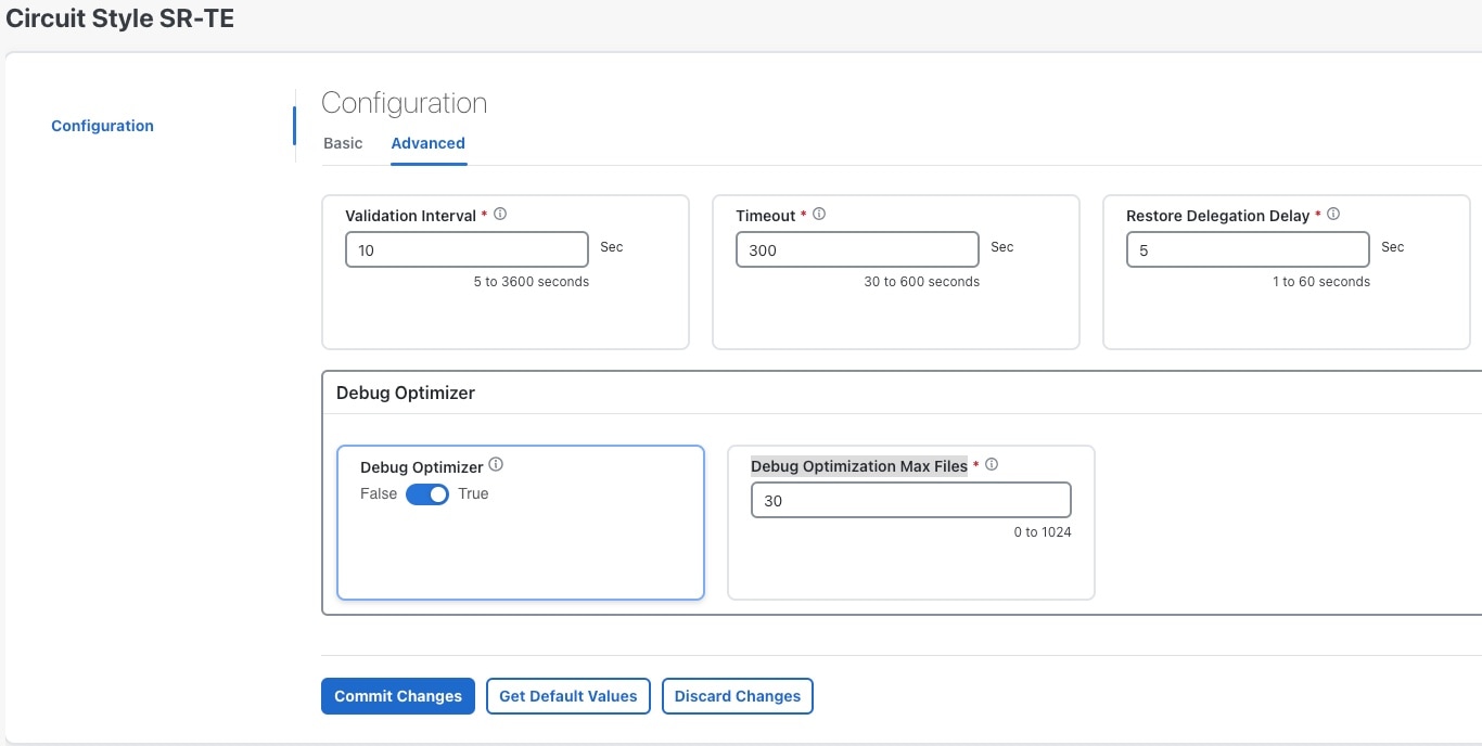
Toggle the Enable switch to True, and enter the global utilization threshold you want to set. In this case, we set the threshold at 80%, and select the Interfaces to Monitor > All Interfaces option. In the Advanced tab, Operation mode is set to Manual. Manual mode allows you to view recommended TTE policies prior and decide whether or not to deploy them. To see information about other options for each configuration setting, hover the mouse over i (help icon). 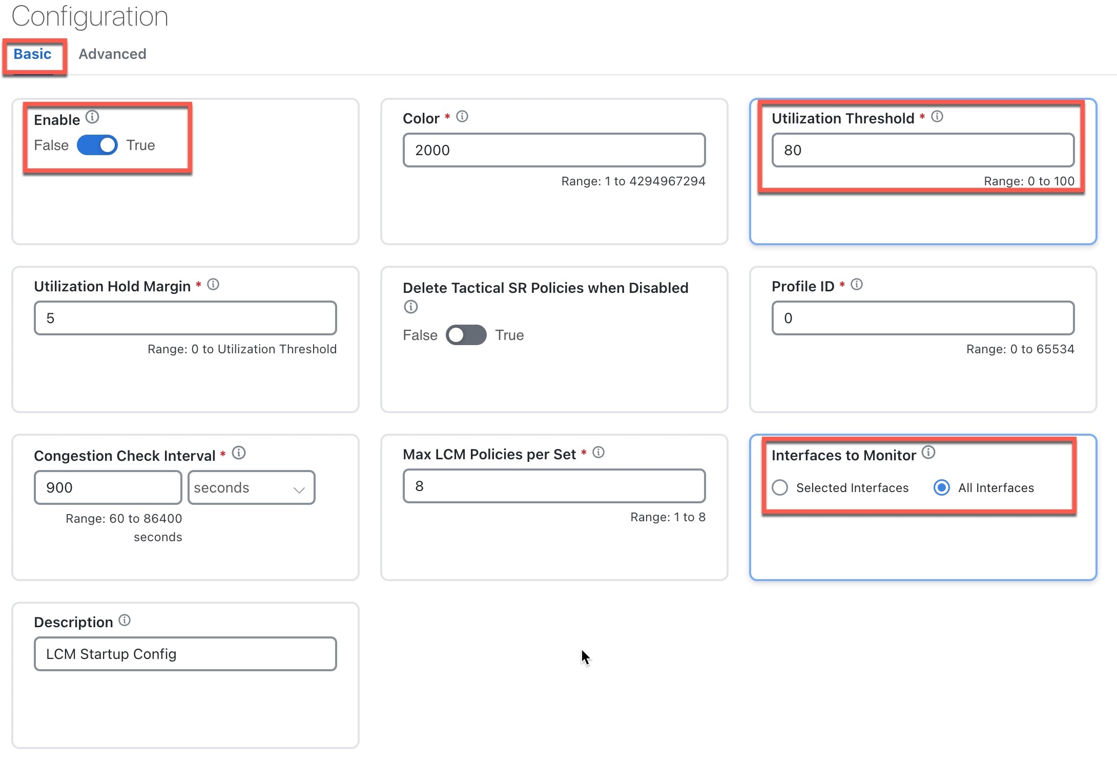  |
||
|
Step 3 |
Click Commit Changes.
|
||
|
Step 4 |
You can also define individual interface thresholds. Go to the Customized Interface Thresholds page (
> Domain-ID >
See the following example and note the defined threshold for cw-xrv60 with interface GigabitEthernet0/0/0/1 is 16%.

|
Step 2: View Link Congestion on the Map
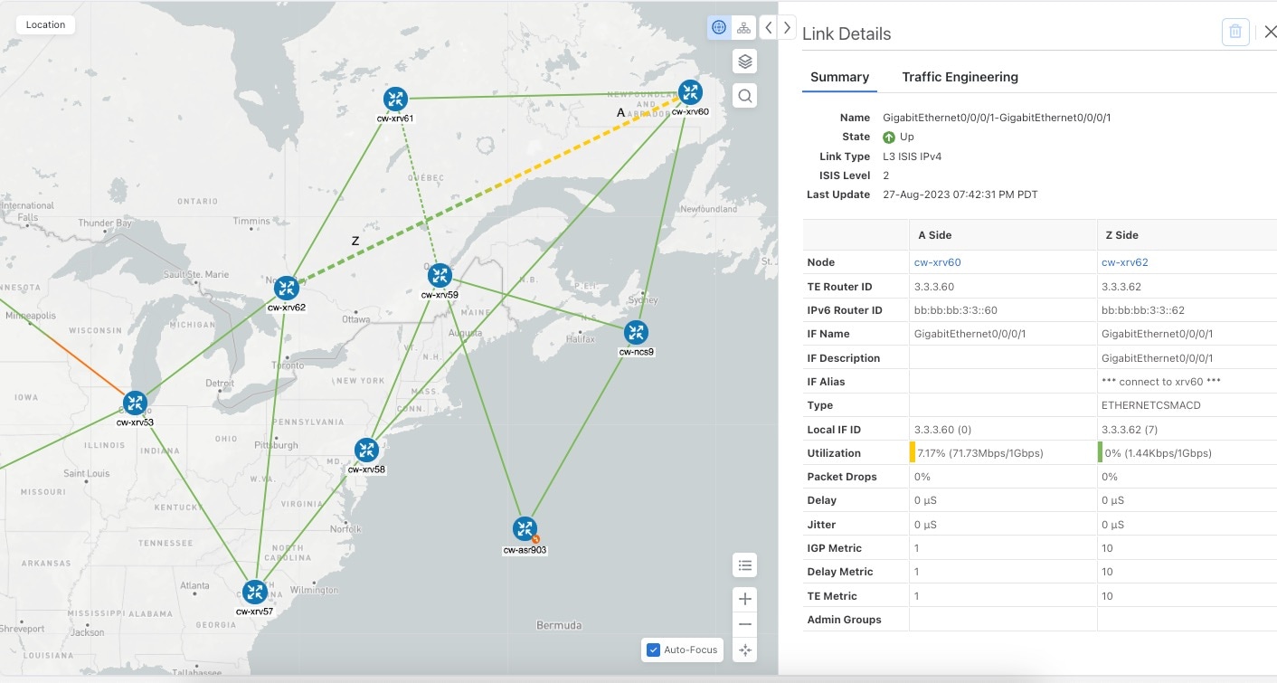
The link between cw-xrv60 and cw-xrv62 is now congested. Let’s see that on the map.
Procedure
|
Step 1 |
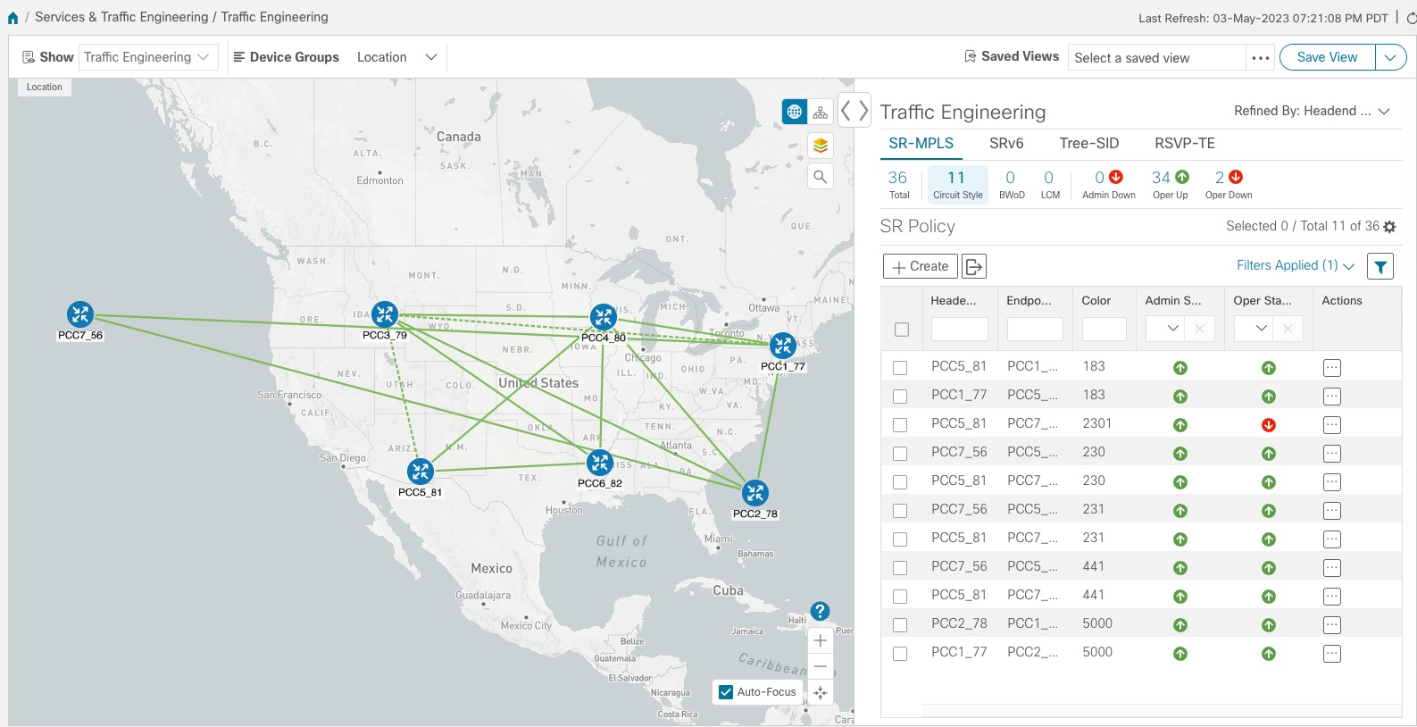
Go to Services & Traffic Engineering > Traffic Engineering. |
|
Step 2 |
Click on the link to view link details, including utilization information. Usage has surpassed the custom LCM threshold defined at 16% for node cw-xrv60 with interface GigabitEthernet0/0/0/1.  |
Step 3: View TTE SR Policy Recommendations in the LCM Operational Dashboard
LCM has detected the congestion and computed tactical policies to mitigate the congestion, which we can preview and then decide whether or not to commit them.
Note that, in this scenario, the congested device is healthy, reachable and in sync with Crosswork. The actions we take and policies we implement will be different if, in addition to congestion, the device is down, unreachable or out of sync.
Procedure
|
Step 1 |
Go to Services & Traffic Engineering > Local Congestion Mitigation. When congestion is detected, the domain displays the urgency type and recommendations that are available. Click the question mark icons to display more information about the urgency type and when the most recent recommendation was given.  |
|
Step 2 |
Open the Operational Dashboard (Services & Traffic Engineering > Local Congestion Mitigation > Domain-ID > ... > Operational Dashboard). The dashboard shows that cw-xrv60 utilization has surpassed 16% and is now at 38.5%. In the Recommended Action column, LCM recommends the deployment of TTE policy solution sets (Recommended Action - Update Set) to address the congestion on the interface.  |
|
Step 3 |
Before committing TTE policies, you can preview the deployment of each TTE policy solution set. Click  The resulting window displays the node, interface, and the recommended action for each TTE policy. From the Preview window, you can select the individual TTE policies, and view different aspects and information as you would normally do in the topology map. You can expand each policy to view individual segments. After reviewing the potential implications on your network, you can decide whether or not to deploy the bypass policies that LCM recommends. The following figure shows the recommended TTE policies for node cw-xrv60.  |
|
Step 4 |
After you are done viewing the recommended TTE policies on the map, go back to the Operational Dashboard and click Commit All. The LCM State column changes to Mitigating. All LCM recommendations per domain must be committed in order to mitigate congestion and produce the expected utilization as shown in the Operational Dashboard. The mitigating solution is based on all LCM recommendations being committed because of dependencies between solution sets.  |
Step 4: Validate TTE SR Policy Deployment
To validate the TTE SR policy deployment, follow the steps given below:
Procedure
|
Step 1 |
With the Operational Dashboard displayed, click the Crosswork will report network events that are detected based on the policies and features you have enabled. For example, if a link drop causes an SR-TE policy to go down, or if LCM detects congestion, an event is displayed in the UI. |
||
|
Step 2 |
Return to the Operational Dashboard to see that the LCM state changes to Mitigated for all TTE policy solution sets.
|
||
|
Step 3 |
Confirm the TTE policy deployment by viewing the topology map. Click  |
||
|
Step 4 |
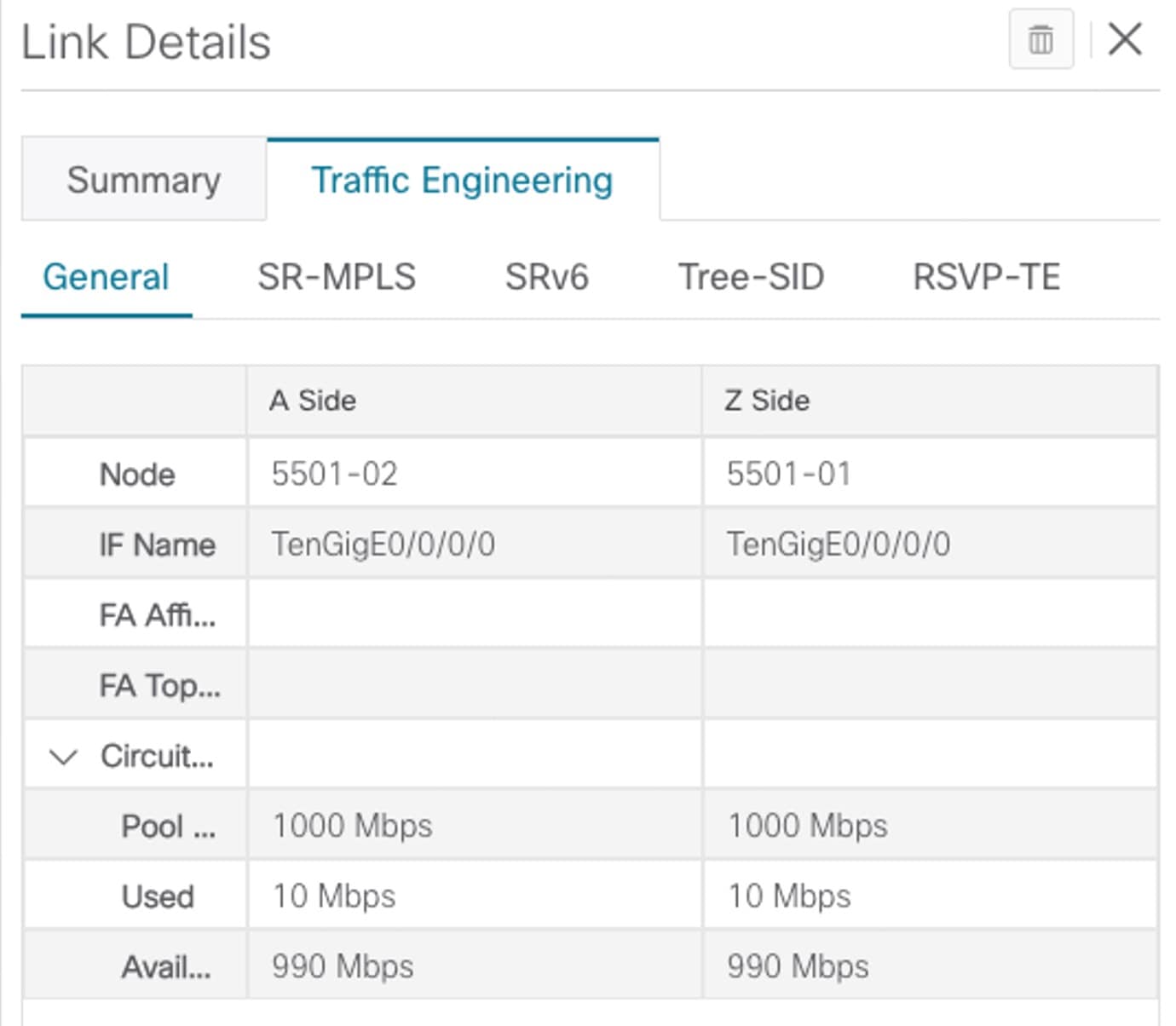
View the SR policy details. From the Actions column of one of the deployed policies, click  |
Step 5: Remove TTE SR policies on LCM Recommendation
After some time, the deployed TTE SR policies may no longer be needed. This occurs if utilization continues to stay under threshold without the LCM-initiated TTE policies. If this is the case, LCM generates new recommended actions to delete the TTE SR policy sets.
To remove the TTE SR policies upon LCM recommendation, follow the steps given below:
Procedure
|
Step 1 |
If needed: Display the topology map and click |
|
Step 2 |
Click Commit All to remove the previously deployed TTE SR policies. |
|
Step 3 |
Confirm the removal by viewing the topology map and SR Policy table. |
LCM Scenario: Summary and Conclusion
In this scenario, we observed how to leverage LCM to alleviate traffic congestion in the network. LCM takes the manual tracking and calculation out of your hands but at the same time gives you control as to whether to implement the congestion mitigation recommendations, or not. You can preview the recommendations and see how the potential deployment will take effect in your network before you deploy them. As traffic changes, LCM tracks the deployed TTE SR policies and decides whether or not they are still needed. If not, LCM recommends deleting them.


 Feedback