Mount the Chassis

Unpack and Inspect the Chassis


Note


The chassis is thoroughly inspected before shipment. If any damage occurred during transportation or any items are missing, contact your customer service representative immediately. Keep the shipping container in case you need to send the chassis back due to damage.

See Package Contents for a list of what shipped with the chassis.


Note


Mounting kits are ordered separately.

Warning


You must install the unit in a restricted access location in the following cases:

  • If you are using a DC power connection and the ambient temperature is more than 50°C.

  • If you are using a centralized DC power connection.


Procedure


Step 1

Remove the chassis from its cardboard container and save all packaging material.

Step 2

Compare the shipment to the equipment list provided by your customer service representative. Verify that you have all items.

Step 3

Check for damage and report any discrepancies or damage to your customer service representative. Have the following information ready:

  • Invoice number of shipper (see the packing slip)

  • Model and serial number of the damaged unit

  • Description of damage

  • Effect of damage on the installation


Desktop-Mount the Chassis

Attach the included rubber feet to the bottom of the unit for added stability when placing on a desktop or other flat surface. Ensure that the fan airflow is not blocked by any obstacles.


Caution


Do not stack one chassis on top of another chassis. If you stack the units, they overheat, which causes the units to power cycle.


Wall-Mount the Chassis

The Adapter Wallmount Kit is required for wallmount installations. When mounting a unit on a wall, ensure that:.

  • The surface you attach the unit to and the fasteners you use are able to support at least 6 kg (13.2 lbs).

  • Cable pull (accidental or otherwise) does not exceed the 2 kg (4.4 lbs) limit.

Follow these steps to mount your chassis on a wall.

Procedure


Step 1

Using a Philips screwdriver, align the Adapter Wallmount Kit brackets with the holes on the side of the unit and attach with four flat head screws provided.

Figure 1. Align and Attach the Adapter Wallmout Kit

Step 2

Secure to the wall using the screws provided.

Warning

 
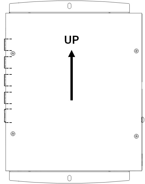
Ensure to install the unit on the wall in the position shown below to ensure proper ventilation of the unit.
Figure 2. Wall Installation Position

Rack-Mount the Chassis

You can mount the unit in a standard 19-inch or 23-inch rack.

Safety Warnings

Take note of the following warnings:


Warning


To conform to the NEBS Seismic Zone 4 requirements, the bracket must be secured, using screws specified by the rack manufacturer, to a NEBS Seismic Zone 4 compliant rack. Such screws are not provided with the bracket kit.


Procedure


Step 1

Using a Philips screwdriver, align the L-brackets with the holes on the side of the unit and attach with four provided flat head screws.

Figure 3. Align the L-brackets

Step 2

Secure this assembly to the rackmount bracket using four pan head screws provided.

Figure 4. Secure the Assembly

Step 3

Secure to the rack using four pan head screws provided.


Ground the Chassis


Tip


This unit is designed for Common Bonding Network (CBN) installations only.

This unit is suitable for installation in network telecommunication facilities and where the National Electrical Code (NEC) applies.


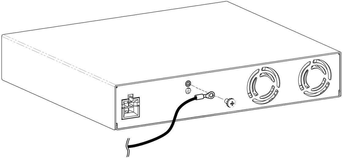
For safety reasons, connect the protective ground lug to a suitable grounding point before applying power, as shown in the following figure.

Safety Warnings

Take note of the following warnings:


Warning


Statement 1101—Connected To Grounded Outlet

In the Scandinavian countries (Denmark, Finland, Iceland, Norway, and Sweden) the appliance must be connected to a grounded outlet.


You will need a Phillips #2 screwdriver and a grounding wire with a gauge of 10 to 14 AWG.

Procedure


Step 1

Expose one end of the grounding wire to approximately 0.75 in. (20 mm).

Step 2

Crimp the ground lug around the exposed wire.

Step 3

Use a Phillips #2 screwdriver and the provided screw and washer to fasten the ground lug to the grounding point on the rear side of the unit.

Figure 5. Fasten the Ground Lug

Step 4

Connect the other end of the wire to a grounding point on the rack.