Installation, Maintenance, and Upgrade

Power the Unit via DC Power Cable

Safety Warnings

Take note of the following warnings:


Warning


  • The unit is designed for Common Bonding Network (CBN) installations only.

  • The unit is suitable for installation in network telecommunication facilities and where the National Electrical Code (NEC) applies.

  • The DC Battery Return (BR) input terminals of the unit are not connected to the equipment frame or grounding means of the equipment and must be configured as isolated DC Return (DC-I) in compliance with GR-1089-CORE requirements.


Warning


DC power connections:

  • Ensure that the unit's power sources have been turned OFF before servicing.

  • An approved external power supply switch or circuit breaker must be installed in the supply lines and be readily accessible to act as a disconnect device. The switch or circuit breaker must disconnect all poles simultaneously and be rated 8 A Max (Quick/Fast).


To power the unit via the power cable:


Note


Applicable wire range: 0.75 to 4.0 mm2 (18 to 12 AWG).

Before you begin

  • Make sure that the chassis ground is connected on the chassis before you begin installing the DC power supply. See Ground the Chassis for the procedure.


Note


Powering options are ordered separately.


Procedure


Step 1

Establish the Ethernet connections to the unit by plugging the appropriate media types into the proper ports of the unit (see Front Panel).
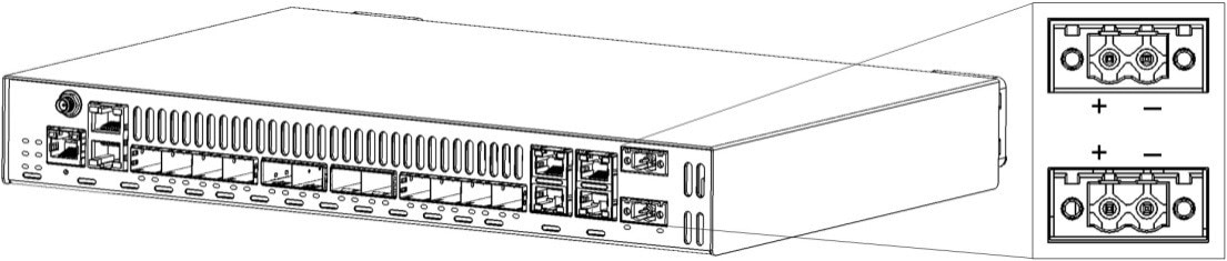
Figure 1. DC Power Input

Step 2

Connect the DC connector to the front of the unit.


Connect to the Network

Establish the Ethernet connections to the unit by plugging the appropriate media types to the proper ports of the unit (see Front Panel).


Note


For more information, refer to the User Material.


Remove and Replace the Fans

This procedure describes how to replace a fan in the event of a fan failure. The fan replacement kit SKY-FANKIT-LT contains two fans.

If a fan failure is reported by the Cisco Provider Connectivity Assurance Sensor LT-S (formerly Skylight element: LT-S) fan monitoring circuit, you must replace the fan. However, as a preventative measure, it is recommended to replace both fans in the event of a failure.


Caution


The fans must be replaced one at a time.


Note


The replacement of the fans should be carefully planned, as the procedure must be completed within five minutes to reduce the thermal impact on the unit.


Safety Warnings

The following are safety guidelines that you must follow for personal safety and to operate the units correctly. All personnel working directly on the units must be trained, authorized, and qualified to perform the tasks described herein. You must read and follow these guidelines before you begin.

  • Power to the unit remains on throughout this process.

  • To avoid personal injury, equipment damage and/or service interruptions, keep your fingers away from the fan's moving parts.

  • This equipment is sensitive to electrostatic discharge (ESD). When handling, ensure you wear a properly functioning heel grounder and/or an anti-static wrist strap or another personal-grounding device.

  • Incorrect handling may void warranty.

Take note of the following warnings:


Warning


Statement 1073—No User-Serviceable Parts

There are no serviceable parts inside. To avoid risk of electric shock, do not open.


Warning


Statement 1093—Avoid Sharp Edges

Risk of personal injury. Avoid sharp edges when installing or removing replaceable units.


Prepare for Fan Replacement

To prepare for fan replacement:

Procedure


Step 1

Log in to the unit where the fan failure occurred.

Step 2

Identify which fan on the unit has malfunctioned:

  1. Access the page ShowAlarm to view alarm status.

  2. Look in the list of alarms for either Fan 1 or Fan 2 failures. The number of the failure corresponds to the defective fan.


Replace the Fan

To replace the fan:

Procedure


Step 1

Loosen the screw that holds the fan cable cover in place, then remove the fan cable cover.

Step 2

Disconnect the cable that connects the fan to the fan connector from the unit's chassis.

Note


You can pull the wire while the retaining clip is depressed.

Step 3

Remove the two screws holding the fan to the unit’s chassis.

Note


Keep the two screws aside.

Step 4

Remove the defective fan, as identified in Prepare for Fan Replacement.

Step 5

Install the new fan in place.

Step 6

Secure the fan to the unit’s chassis using the two screws kept aside.

Step 7

Reconnect the fan cables.

Step 8

Install the fan cable cover, securing it in place with the screw.

Step 9

Ensure that the fan is fully functional by following the instructions in Fan Replacement Verification.

Step 10

(Optional) To replace the other fan as a preventative measure, continue with Optional Preventative Maintenance Fan Replacement.


Optional Preventative Maintenance Fan Replacement

To perform an optional fan preventive maintenance:

Procedure


Step 1

Disconnect the cable that connects the other fan to the fan connector from the unit’s chassis.

Note


You can pull the wire while the retaining clip is depressed.

Step 2

Remove the two screws holding the fan to the unit’s chassis.

Note


Keep the two screws aside.

Step 3

Remove the fan to be replaced as a preventative measure.

Step 4

Install the new fan in place.

Step 5

Secure the fan to the unit’s chassis using the two screws kept aside.

Step 6

Reconnect the fan cables.

Step 7

Install the fan cable cover, securing it in place with the screw.

Step 8

Ensure that the fan is fully functional by following the instructions in Fan Replacement Verification.


Fan Replacement Verification

To verify the fan replacement:

Procedure


Step 1

Log in to the unit where the fan failure occurred.

Step 2

Access the page Show ▶ Alarm and confirm that the fan failure alarms are no longer listed in the grid.