Features
The Cisco® Provider Connectivity Assurance Sensor LT-S (formerly Accedian Skylight LT-S Performance Element) is a dense, multiport, 1/10 Gigabit Ethernet platform with ultra-low-latency packet forwarding and jitter. Designed for high-availability applications requiring MEF-type service assurance, the Assurance Sensor LT-S is optimized for scalable service delivery and high-precision performance monitoring. It is an ideal edge, aggregation, or external network-to-network interface (ENNI) unit for demanding wireless backhaul, SLA-backed business services, Ethernet wholesale, and dark fiber termination applications. Switch-free aggregation offers near-zero-latency multiservices for multitenant and multioperator endpoints.
The LT-S provides all the tools to establish, validate, and monitor Layer 2 and Layer 3 services in a single unit. It is a flexible, scalable alternative to switches and routers when delivering resilient services over optical linear or G.8032 ring topologies. Zero-touch provisioning and IPv4/IPv6 management make the LT-S easy to deploy, manage, and secure.
Fully integrated with the Cisco Provider Connectivity Assurance platform, the LT-S supports service delivery automation, scalable metrics collection, and reporting—along with actionable insights delivery and machine learning for accelerated service rollout and improved operational efficiencies.
The LT-S interoperates with other Provider Connectivity Assurance Sensors to deliver a scalable end-to-end and core-to-edge performance-assured networking solution tailored to your applications.
The following table lists the features of the Assurance Sensor LT-S.
|
Feature |
Description |
|---|---|
|
Form factor |
1RU |
|
Rack mount |
Standard 19-inch (48.3 cm) or 23-inch (58.42 cm) rack |
|
Airflow |
Front to rear |
|
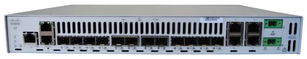
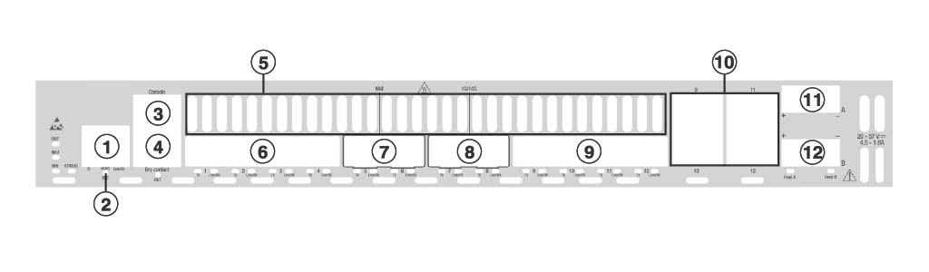
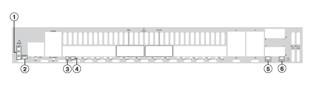
Management port |
Built-in One RJ-45 connector (10M/100M/1GbE) |
|
Traffic ports |
Four SFP connectors (10M/100M/1GbE) Four SFP+ connectors (1G/10GbE) Four SFP/RJ-45 connectors (10M/100M/1GbE combo ports) |
|
Console port |
One RJ-45 connector (RS-232) |
| Dry contact inputs | One RJ-45 connector (four dry contacts) |
|
Fans |
Two fans for front-to-rear cooling |
The following table lists the regulation and standard compliance features of the Assurance Sensor LT-S.
|
Feature |
Description |
|---|---|
|
Safety |
IEC 62368-1, EN IEC 62368-1, AS/NZS 62368.1, CSA/UL 62368-1, GB 4943.1, J62368-1, SASO-IEC 62368-1 |
|
EMC - Emission (Class A) |
CISPR 32, EN 55032, FCC Part 15 (CFR 47), ICES-003, AS/NZS CISPR 32 |
|
EMC - Immunity |
EN 55035 |
|
Telco |
NEBS Level-3: GR-63, GR-1089 |
|
Enviro |
RoHS: IEC 63000, EN IEC 63000 |


 Feedback