Overview

Features

Cisco® Provider Connectivity Assurance Sensor Modules (formerly Accedian Skylight Sensor Modules) allow you to more effectively address end-to-end service lifecycles, from Service Activation Testing (SAT) to assurance management and service demarcation. The small form factor of the modules helps keep them power-efficient, and all management capabilities are automated and orchestrated through the Provider Connectivity Assurance Sensor Control software.

These modules are equipped with a fully featured Field-Programmable Gate Array (FPGA) capable of active Layer 2 through 4 testing and traffic generation—without compromising performance, scalability, and precision. This makes Assurance Sensor Modules an ideal fit for cost- and space-sensitive applications where performance is a key service differentiator.
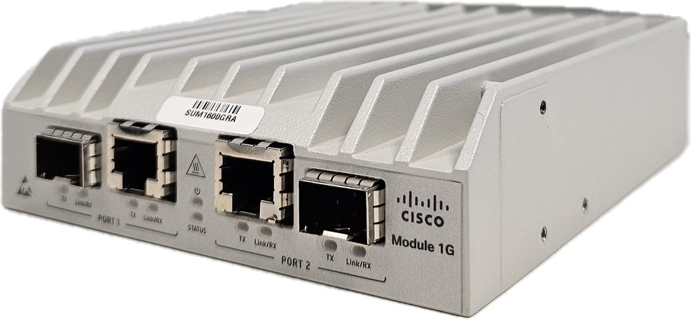
Figure 1. Cisco Provider Connectivity Assurance Sensor Module 1G

The following table lists the features for the Sensor Module 1G.

Table 1. Sensor Module 1G Features

Feature

Description

Form factor

1 RU

Rack mount

Standard 19-in. (48.3 cm) or 23-in (58.42 cm) rack

Optical ports

Two fixed optical connectors

Copper ports

Two fixed copper connectors

Package Contents

The package contents for the Sensor Module 1G include:

  • Sensor Module 1G (1x)

  • AC model: power cord retainer clip (1x)

  • Drywall anchor kit (1x)

  • Rubber feet (4x)

  • RJ-45 patch cord (1x)

  • Cisco Provider Connectivity Assurance Sensor Module 1G—This document contains URLs that point to the hardware installation guide, regulatory compliance and safety information guide, warranty, and licensing pages, and a QR code that points to the management center Documentation Portal

Serial Number Locations

The Serial Number (SN) and the Media Access Control (MAC) address are located at the bottom of the Sensor Module 1G.

Front Panel

The following figure shows the front panel features for the Sensor Module 1G. See Front Panel LEDs for a description of the LEDs.

Figure 2. Sensor Module 1G Front Panel

1

Optical port 1

SFP 1000 Mbps Ethernet Port 1 (combo models only)

2

Copper port 1

RJ-45 100/1000 Mbps Ethernet Port 1

3

Copper port 2

RJ-45 100/1000 Mbps Ethernet Port 2

4

Optical port 2

SFP 1000 Mbps Ethernet Port 2 (combo models only)

5

Hot surface

Note that the surface is hot to touch.

6

ESD

Electrostatic Discharge

Front Panel LEDs

The following figure shows the front panel LEDs and describes their states.

Figure 3. Sensor Module 1G Front Panel LEDs

1

TX LED:

  • Off—Port is not transmitting data.

  • Flashing—Port is transmitting data.

2

Link/RX LED:

  • Off—Link is inactive.

  • On—Link is active.

  • Flashing—Port is receiving data.

3

PWR LED:

  • Off—Device is unpowered.

  • On—Device is powered.

4

STATUS LED:

  • Off—Device is not ready.

  • On—Device is ready, but unmanaged.

  • Flashing—Device is ready, and remotely managed.

    • Slow flashing means the system is currently managed by a remote controller.

    • Fast flashing means a critical system failure is detected.

Rear Panel

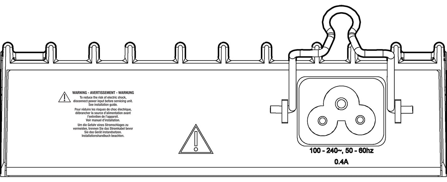
The following figure shows the rear panel of the Sensor Module 1G - AC Input Power Model.

Figure 4. Sensor Module 1G Rear Panel - AC Input Power Model

1

AC cord retainer

Secure the AC cord through the retainer clip

2

AC power input

Connect appropriate power cord here

The following figure shows the rear panel of the Sensor Module 1G - DC Input Power Model.

Figure 5. Sensor Module 1G Rear Panel - DC Input Power Model

1

DC power input (Feed A and B)

Connect appropriate power source here

Note


The connector has two polarized DC feeds

2

Functional ground connection

Fasten the ground lug here

Power Supply

The following table lists the specifications for each power supply used in the Sensor Module 1G.

Table 2. Power Specifications

Description

Specification

Input power ratings

AC: 100 to 240 V AC, 50 to 60 Hz, 0.5 to 0.4 AMax

DC: 20 to 57 V DC, 0.75 AMax

Output power ratings

SFP: 2.6 WMax per port, 3.4 WMax for all ports

Warning


Transceivers used in the ports must stay within their specifications under all operating conditions of the system.

Power consumption

7.8 WMax (27 BTU/hrMax)

Hardware Specifications

The following table contains hardware specifications for the Sensor Module 1G.

Dimensions (H x W x D)

1.4 x 4.7 x 5.3 inches (3.6 x 11.9 x 13.3 cm)

Weight

1.4 lb (0.63 kg)

Temperature

Operating:

  • Commercial: 32 to 122°F (0 to 50°C)

  • Hardened*: -40 to 149°F (-40 to 65°C)

    *Cold Start: -13°F (-25°C)

Nonoperating: -40 to 158°F (-40 to 70°C)

Humidity

Operating and nonoperating: 5 to 95 % noncondensing

Altitude

6562 ft (2000 m), above sea level

Product ID Numbers

The following table lists the field-replaceable PIDs associated with the Sensor Module 1G. If any internal components fail, you must get a return material authorization (RMA). See the Cisco Returns Portal for more information.

Table 3. Sensor Module 1G PIDs

PID

Description

SKY-MOD1G-HR-A

Module 1G - 2xCombo - Single Internal AC Power Supply with Relay - Hardened DHCP enabled

SKY-MOD1G-DD

Module 1G - 2xCombo - Dual DC Power Supply DHCP enabled

SKY-MOD1G-HR-DD

Module 1G - 2xCombo - Dual DC Power Supply with Relay - Hardened DHCP enabled

SKY-MOD1G-H-A

Module 1G - 2xCombo - Single Internal AC Power Supply - Hardened DHCP enabled

SKY-MOD1G-H-DD

Module 1G - 2xCombo - Dual DC Power Supply - Hardened DHCP enabled

Power Cord Specifications

Each AC power input requires a separate power cord. Power cords are available for connection to the Sensor Module 1G.

If you do not order the optional power cord with the system, you are responsible for selecting the appropriate power cord for the product. Using a incompatible power cord with this product may result in electrical safety hazard.

PID

Description

SKY-PC-NA

North America – C5 termination

SKY-PC-EUR

Europe – C5 termination

SKY-PC-UK

United Kingdom – C5 termination

SKY-PC-JPN

Japan – C5 termination

SKY-PC-IND

India – C5 termination

SKY-PC-SIN

Singapore – C5 termination

SKY-PC-AUS

Australia / New Zealand – C5 termination

SKY-PC-SWI

Switzerland – C5 termination

SKY-PC-ITA

Italy – C5 termination

SKY-PC-ISL

Israel – C5 termination

SKY-PC-TWN

Taiwan – C5 termination

SKY-PC-ARG

Argentina – C5 termination

SKY-PC-BRZ

Brazil – C5 termination

SKY-PC-C20

C20 – C5 termination

SKY-PC-C14

C14 – C5 termination

SKY-PC-CHN

China – C5 termination

Note


Only the approved power cords for the Sensor Module 1G are supported.