The documentation set for this product strives to use bias-free language. For the purposes of this documentation set, bias-free is defined as language that does not imply discrimination based on age, disability, gender, racial identity, ethnic identity, sexual orientation, socioeconomic status, and intersectionality. Exceptions may be present in the documentation due to language that is hardcoded in the user interfaces of the product software, language used based on RFP documentation, or language that is used by a referenced third-party product. Learn more about how Cisco is using Inclusive Language.
Although ACI fabric-wide flooding is disabled by default, flooding within a bridge domain is enabled by default. Because flooding
within a bridge domain is enabled by default, clients can connect to DHCP servers within the same EPG. However, when the DHCP
server is in a different EPG or Virtual Routing and Forwarding (VRF) instance than the clients, DHCP Relay is required. Also,
when Layer 2 flooding is disabled, DHCP Relay is required.
Note
When the ACI fabric acts as a DHCP relay, it inserts the DHCP Option 82 (the DHCP Relay Agent Information Option) in DHCP
requests that it proxies on behalf of clients. If a response (DHCP offer) comes back from a DHCP server without Option 82,
it is silently dropped by the fabric. When ACI acts as a DHCP relay, DHCP servers providing IP addresses to compute nodes
attached to the ACI fabric must support Option 82. Windows 2003 and 2008 do not support option 82 but Windows 2012 does.
The figure below shows the managed objects in the management information tree (MIT) that can contain DHCP relays: user tenants,
the common tenant, the infra tenant, the mgmt tenant, and fabric access.
Figure 1. DHCP Relay Locations in the MIT
Note
DHCP relay is limited to a single subnet per bridge domain.
The figure below shows the logical relationships of the DHCP relay objects within a user tenant.
Figure 2. Tenant DHCP Relay
The DHCP Relay profile contains one or more providers. An EPG contains one or more DHCP servers, and the relation between
the EPG and DHCP Relay specifies the DHCP server IP address. The consumer bridge domain contains a DHCP label that associates
the provider DHCP server with the bridge domain. Label matching enables the bridge domain to consume the DHCP Relay.
Note
The bridge domain DHCP label must match the DHCP Relay name.
The DHCP label object also specifies the owner. The owner can be a tenant or the access infrastructure. If the owner is a
tenant, the ACI fabric first looks within the tenant for a matching DHCP Relay. If there is no match within a user tenant,
the ACI fabric then looks in the common tenant.
DHCP Relay operates in the Visable mode as follows: Visible—the provider's IP and subnet are leaked into the consumer's VRF. When the DHCP Relay is visible, it is exclusive to the consumer's
VRF.
While the tenant and
access DHCP Relays are configured in a similar way, the following use cases
vary accordingly:
Common tenant DHCP Relays can be used by any tenant.
Infra tenant DHCP Relays are exposed selectively by the ACI fabric service provider to other tenants.
Fabric Access
(infraInfra)
DHCP Relays can be used by any tenant and allow more granular configuration of
the DHCP servers. In this case, it is possible to provision separate DHCP
servers within the same bridge domain for each leaf switch in the node profile.
DNS
The ACI fabric DNS service is contained in the fabric managed object. The fabric global default DNS profile can be accessed
throughout the fabric. The figure below shows the logical relationships of the DNS-managed objects within the fabric.
Figure 3. DNS
A VRF (context) must contain a dnsLBL object in order to use the global default DNS service. Label matching enables tenant VRFs to consume the global DNS provider.
Because the name of the global DNS profile is “default,” the VRF label name is "default" (dnsLBL name = default).
In-Band and
Out-of-Band Management Access
The mgmt tenant provides a convenient means to configure access to fabric management functions. While fabric management functions
are accessible through the APIC, they can also be accessed directly through in-band and out-of-band network policies.
Static and Dynamic Management Access
APIC supports both static and dynamic management access. For simple deployments where users manage the IP addresses of a
few leaf and spine switches, configuring static in-band and out-of-band management connectivity is simpler. For more complex
deployments, where you might have a large number of leaf and spine switches that require managing many IP addresses, static
management access is not recommended. For detailed information about static management access, see Cisco APIC and Static Management Access.
In-Band Management
Access
The following figure shows an overview of the mgmt tenant in-band fabric management access policy.
Figure 4. In-Band Management Access Policy
The management profile includes the in-band EPG MO that provides access to management functions via the in-band contract
(vzBrCP). The vzBrCP enables fvAEPg, l2extInstP, andl3extInstP EPGs to consume the in-band EPG. This exposes the fabric management to locally connected devices, as well as devices connected
over Layer 2 bridged external networks, and Layer 3 routed external networks. If the consumer and provider EPGs are in different
tenants, they can use a bridge domain and VRF from the common tenant. Authentication, access, and audit logging apply to these connections; any user attempting to access management functions
through the in-band EPG must have the appropriate access privileges.
The figure below shows
an in-band management access scenario.
Figure 5. In-Band
Management Access Scenario
Out-of-Band
Management Access
The following figure
shows an overview of the mgmt tenant out-of-band fabric management access
policy.
Figure 6. Out-of-Band
Management Access Policy
The management profile
includes the out-of-band EPG MO that provides access to management functions
via the out-of-band contract (vzOOBBrCP). The
vzOOBBrCP enables the external management instance
profile (mgmtExtInstP) EPG to consume the out-of-band EPG. This
exposes the fabric node supervisor ports to locally or remotely connected
devices, according to the preference of the service provider. While the
bandwidth of the supervisor ports will be lower than the in-band ports, the
supervisor ports can provide direct access to the fabric nodes when access
through the in-band ports is unavailable. Authentication, access, and audit
logging apply to these connections; any user attempting to access management
functions through the out-of-band EPG must have the appropriate access
privileges. When an administrator configures an external management instance
profile, it specifies a subnet range for devices that are allowed out-of-band
access. Any device not in this range will not have out-of-band access.
The figure below shows
how out-of-band management access can be consolidated through a dedicated
switch.
Figure 7. Out-of-Band
Access Scenario
While some service providers choose to restrict out-of-band connectivity to local connections,
others can choose to enable routed or bridged connections from external networks. Also,
a service provider can choose to configure a set of policies that include both in-band
and out-of-band management access for local devices only, or both local and remote
devices.
Note
Starting with APIC release 1.2(2), when a contract is provided on an out-of-band node
management EPG, the default APIC out-of-band contract source address is the local subnet
that is configured on the out-of-band node management address. Previously, any address
was allowed to be the default APIC out-of-band contract source address.
IPv6 Support
The ACI fabric supports the following IPv6 features for in-band and out-of-band interfaces, tenant addressing,
contracts, shared services, routing, Layer 4 - Layer 7 services, and
troubleshooting:
IPv6 address
management, pervasive software virtual interface (SVI) bridge domain subnets,
outside network external interface addresses, and routes for shared services
such as load balancers or intrusion detection.
Neighbor
Discovery using ICMPv6 messages known as router advertisements (RA) and router
solicitations (RS), and Duplicate Address Detection (DAD),
Stateless Address Auto configuration (SLAAC) and DHCPv6.
Bridge domain
forwarding.
Troubleshooting (see the atomic counters, SPAN, iping6, and traceroute topics in the Troubleshooting Chapter).
IPv4 only, IPv6 only, or dual stack configuration of in-band and out-of-band interfaces.
Limitations of the
current ACI fabric IPv6 implementation include the following:
Multicast
Listener Discovery (MLD) snooping is not supported.
For IPv6 management, only static addresses are permitted; dynamic IPv6 pools are not supported for IPv6 management.
IPv6 tunnel
interfaces (Intra-Site Automatic Tunnel Addressing Protocol, 6to4 and so forth)
are not supported within the fabric; IPv6 tunnel traffic run over the fabric is
transparent to the fabric.
ACI fabric interfaces
can be configured with link local, global unicast, and multicast IPv6
addresses.
Note
While many of the examples provided in this manual use IPv4 addresses, IPv6 addresses could also be used.
A global unicast address can be routed across the public Internet;
it is globally unique within a routing domain. A Link Local Address (LLA) has
link-local scope and is unique on the link (subnet). The LLA cannot be routed
across subnets. These are used by control protocols such as neighbor discovery
or OSPF. Multicast addresses are used by IPv6 control protocols such as
Neighbor Discovery to deliver packets to more than one endpoint. These are not
configurable; they are automatically generated by the protocol components.
Global Unicast
Addresses
An administrator can
manually specify one or more complete 128-bit IPv6 global unicast addresses on
an interface in compressed or uncompressed format. For example, the
administration can specify the address in one of the following formats:
'2001:0000:0000:0001:0000:0000:0000:0003', '2001:0:0:1:0:0:0:3',
'2001:0:0:1::3'. In the ACI fabric naming property, an IPv6 address is always
represented in the compressed format. In the above example, the Relative Name
is: 2001:0:0:1::3. The administrator can choose any mask length as appropriate
for the address.
An administrator can also specify an ACI fabric IPv6 global unicast address in EUI-64 format. As specified in RFC2373, Extended
Unique Identifier (EUI) enables a host to assign itself a unique 64-bit IPv6 interface identifier (EUI-64). The IPv6 EUI-64
format address is obtained by incorporating the switch MAC address within the 128-bit IPv6 global unicast address. This feature
of IPv6 eliminates the need for manual configuration or DHCP. An IPv6 address for a bridge domain or Layer 3 interface specified
in the EUI-64 format is formed this way: <IPv6 prefix>::/<mask>/eui64 where the mask is <=64. For example, 2002::/64/eui64
is what the administrator specifies, and the switch assigns the address as 2002::222:bdff:fef8:19ff/64. The switch uses the
switch MAC address to create the EUI-64 address. The formed IPv6 address is contained in the operAddr field of the ipv6If object.
Note
The EUI-64 format
can only be used for pervasive bridge domain and Layer 3 interface addresses.
It cannot be used for other IP fields in the fabric such as an external server
address or for DHCP relay.
Bridge domain subnets
and Layer 3 external interface IP addresses can be IPv6 global addresses with a
mask ranging from /1 to /127. A bridge domain can contain multiple IPv4 and
IPv6 subnets. To support IPv4 and IPv6 address on the same L3 external
interface, the administrator creates multiple interface profiles. When an EPG
or external EpP gets deployed on the switch, the presence of a manually
configured link-local address for the equivalent bridge domain/L3 Interface or
an IPv6 address for the subnet/address field results in the creation of
ipv6If
interface in the switch.
Link-Local
Addresses
One Link-Local Address (LLA) can be assigned to an interface. The LLA can be autogenerated or configured by an administrator.
By default, an ACI LLA is autogenerated by the switch in EUI-64 format. An administrator must configure at least one global
address on the interface for an autogenerated LLA to be generated on the switch. The autogenerated address is saved in the
operllAddr field of the ipv6If MO. For pervasive SVIs the MAC address used is the same as the configured interface MAC address. For other kinds of interfaces
the switch MAC address is used. An administrator has the option to manually specify a complete 128-bit IPv6 link-local address
on an interface in compressed or uncompressed format.
Note
The switch hardware tables are limited to one LLA per Virtual Routing and Forwarding (VRF) instance.
Each pervasive bridge domain can have a single IPv6 LLA. This LLA can be set by an administrator, or can be automatically
configured by the switch when one isn't provided. When automatically configured, the switch forms the LLA in the modified
EUI-64 format where the MAC address is encoded in the IPv6 address to form a unique address. A pervasive bridge domain uses
one LLA on all the leaf nodes.
Follow these guidelines for setting LLAs:
For external SVI and VPC members, the LLA is unique for every leaf node.
LLAs can be changed to manual (non-zero manually specified link-local addresses) or auto (by manually setting the specified
link-local address to zero) anytime in the lifecycle of the interface.
LLAs specified by an administrator must conform to the IPv6 link-local format (FE80:/10).
The IPv6 interface MO (ipv6If) is created on the switch upon the creation of the first global address on the interface, or when an administrator manually
configures an LLA, whichever happens first.
An administrator-specified LLA is represented in the llAddr property in the bridge domain and Layer 3 interface objects in the logical model.
The LLA used by the switch (either from llAddr or autogenerated when llAddr is zero is represented in the operLlAddr property in the corresponding ipv6If object.
Operational LLA-related errors like duplicate LLAs are detected by the switch during Duplicate Address Detection process and
recorded in operStQual field in the ipv6If object or raise faults as appropriate.
Apart from the llAddr fields, an LLA (FE80:/10) cannot be a valid address in any other IP address field in the APIC (such as external server addresses
or bridge domain subnets) as these addresses cannot be routed.
Static
Routes
ACI IPv6 static routes
are similar to what is supported in the IPv4, except for the address and prefix
format differences in the configurations. The following types of static routes
are typically handled by IPv6 static route module:
Local Routes: Any /128 address configured on an interface leads to a local route that points to the CPU.
Direct routes: For any configured address on a pervasive BD, the policy element pushes a subnet route pointing to an IPv4
proxy tunnel destination on the spine. For any configured address on a non-pervasive Layer 3 external interface, the IPv6
manager module automatically pushes a subnet route pointing to the CPU.
Static routes pushed from PE: Used for external connectivity. The next hop IPv6 address for such routes can be on a directly
connected subnet on the external router or a recursive next hop that can be resolved to a real next hop on a directly connected
subnet. Note that the interface model does not allow an interface as a next hop (though it is supported in the switch). Used
to enable shared services across tenants, the next hop for shared-services static routes is located in the shared services
Virtual Routing and Forwarding (VRF) instance, which is different from the tenant VRF, where the route is installed on the
ingress leaf switches.
Neighbor
Discovery
The IPv6 Neighbor Discovery (ND) protocol is responsible for the address auto configuration of nodes, discovery of other nodes
on the link, determining the link-layer addresses of other nodes, duplicate address detection, finding available routers and
DNS servers, address prefix discovery, and maintaining reachability information about the paths to other active neighbor nodes.
ND-specific Neighbor Solicitation or Neighbor Advertisement (NS or NA) and Router Solicitation or Router Advertisement (RS
or RA) packet types are supported on all ACI fabric Layer 3 interfaces, including physical, Layer 3 sub interface, and SVI
(external and pervasive). Up to APIC release 3.1(1x), RS/RA packets are used for auto configuration for all Layer 3 interfaces
but are only configurable for pervasive SVIs.
Starting with APIC release 3.1(2x), RS/RA packets are used for auto configuration and are configurable on Layer 3 interfaces
including routed interface, Layer 3 sub interface, and SVI (external and pervasive).
ACI bridge domain ND always operates in flood mode; unicast mode is not supported.
The ACI fabric ND
support includes the following:
Interface policies
(nd:IfPol)
control ND timers and behavior for NS/NA messages.
ND prefix policies (nd:PfxPol) control RA messages.
Configuration of
IPv6 subnets for ND (fv:Subnet).
ND interface
policies for external networks.
Configurable ND
subnets for external networks, and arbitrary subnet configurations for
pervasive bridge domains are not supported.
Configuration options
include the following:
Adjacencies
Configurable Static Adjacencies: (<vrf, L3Iface, ipv6 address> --> mac address)
Dynamic Adjacencies: Learned via exchange of NS/NA packets
Duplicate address
detection (DAD) discovers any other node on the link that is already using the
address being configured. DAD is performed for both link-local and global
addresses. Each configured address maintains the following DAD states:
NONE—This is the
state when the address is initially created before attempting the DAD.
VALID—This is the
state that represents the address has successfully passed the DAD process
without detecting the address as a duplicate address.
DUP—This is the
state that represents the address is found as duplicate on the link.
Any configured address
is usable for sending and receiving IPv6 traffic only if its DAD state is
VALID.
Stateless Address
Autoconfiguration (SLAAC) and DHCPv6
The following host
configurations are supported:
SLAAC only
DHCPv6 only
SLAAC and DHCPv6 stateless used together use SLAAC for address configuration only, but uses DHCPv6 for DNS resolution and
other functions.
IPv6 addresses are supported for DHCP relay. DHCPv6 relay applies across Virtual Routing and Forwarding (VRF) instances. DHCP
relay over VLAN and VXLAN are also supported. DHCPv4 works in conjunction with DHCPv6.
Routing Within the
Tenant
The Application Centric Infrastructure (ACI) fabric provides tenant default gateway functionality and routes between the
fabric virtual extensible local area (VXLAN) networks. For each tenant, the fabric provides a virtual default gateway or Switched
Virtual Interface (SVI) whenever a subnet is created on the APIC. This spans any switch that has a connected endpoint for
that tenant subnet. Each ingress interface supports the default gateway interface and all of the ingress interfaces across
the fabric share the same router IP address and MAC address for a given tenant subnet.
Configuring Route
Reflectors
ACI fabric route reflectors use multiprotocol BGP (MP-BGP) to distribute external routes within the fabric. To enable route
reflectors in the ACI fabric, the fabric administrator must select the spine switches that will be the route reflectors, and
provide the autonomous system (AS) number. It is recommended to configure at least two spine nodes per pod as MP-BGP route
reflectors for redundancy.
After route reflectors are enabled in the ACI fabric, administrators can configure connectivity to external networks through
leaf nodes using a component called Layer 3 Out (L3Out). A leaf node configured with an L3Out is called a border leaf. The
border leaf exchanges routes with a connected external device via a routing protocol specified in the L3Out. You can also
configure static routes via L3Outs.
After both L3Outs and spine route reflectors are deployed, border leaf nodes learn external routes via L3Outs, and those external
routes are distributed to all leaf nodes in the fabric via spine MP-BGP route reflectors.
Check the Verified Scalability Guide for Cisco APIC for your release to find the maximum number of routes supported by a leaf.
Common Pervasive
Gateway
Multiple ACI fabrics
can be configured with an IPv4 common gateway on a per bridge domain basis.
Doing so enables moving one or more virtual machines (VM) or conventional hosts
across the fabrics while the host retains its IP address. VM host moves across
fabrics can be done automatically by the VM hypervisor. The ACI fabrics can be
co-located, or provisioned across multiple sites. The Layer 2 connection
between the ACI fabrics can be a local link, or can be across a routed WAN
link. The following figure illustrates the basic common pervasive gateway
topology.
Figure 8. ACI Multi-Fabric
Common Pervasive Gateway
The per-bridge domain
common pervasive gateway configuration requirements are as follows:
The bridge domain
MAC (mac)
values for each fabric must be unique.
Note
The default
bridge domain MAC (mac) address values are the same for all ACI fabrics.
The common pervasive gateway requires an administrator to configure the bridge
domain MAC (mac) values to be unique for each ACI fabric.
The bridge domain
virtual MAC (vmac) address and the subnet virtual IP address must
be the same across all ACI fabrics for that bridge domain. Multiple bridge
domains can be configured to communicate across connected ACI fabrics. The
virtual MAC address and the virtual IP address can be shared across bridge
domains.
WAN and Other
External Networks
External routers that connect to the
WAN and the enterprise core connect to the front panel interfaces of the leaf
switch. The leaf switch interface that connects to the external router can be
configured as a bridged interface or a routing peer.
Router Peering and
Route Distribution
As shown in the figure
below, when the routing peer model is used, the leaf switch interface is
statically configured to peer with the external router’s routing protocol.
Figure 9. Router
Peering
The routes that are
learned through peering are sent to the spine switches. The spine switches act
as route reflectors and distribute the external routes to all of the leaf
switches that have interfaces that belong to the same tenant. These routes are
longest prefix match (LPM) summarized addresses and are placed in the leaf
switch's forwarding table with the VTEP IP address of the remote leaf switch
where the external router is connected. WAN routes have no forwarding proxy. If
the WAN routes do not fit in the leaf switch's forwarding table, the traffic is
dropped. Because the external router is not the default gateway, packets from
the tenant endpoints (EPs) are sent to the default gateway in the ACI fabric.
Networking
Domains
A fabric
administrator creates domain policies that configure ports, protocols, VLAN
pools, and encapsulation. These policies can be used exclusively by a single
tenant, or shared. Once a fabric administrator configures domains in the ACI
fabric, tenant administrators can associate tenant endpoint groups (EPGs) to
domains.
The following networking domain profiles can be configured:
VMM domain
profiles (vmmDomP) are required for virtual machine hypervisor
integration.
Physical domain
profiles (physDomP) are typically used for bare metal server
attachment and management access.
Bridged outside
network domain profiles (l2extDomP) are typically used to connect a bridged
external network trunk switch to a leaf switch in the ACI fabric.
Routed outside
network domain profiles (l3extDomP) are used to connect a router to a leaf
switch in the ACI fabric.
Fibre Channel domain profiles (fcDomP) are used to connect Fibre Channel VLANs and VSANs.
A domain is configured
to be associated with a VLAN pool. EPGs are then configured to use the VLANs
associated with a domain.
Note
EPG port and VLAN
configurations must match those specified in the domain infrastructure
configuration with which the EPG associates. If not, the APIC will raise a
fault. When such a fault occurs, verify that the domain infrastructure
configuration matches the EPG port and VLAN configurations.
Bridged and Routed
Connectivity to External Networks
Outside network managed objects enable Layer 2 and Layer 3 tenant connectivity to external networks. The GUI, CLI, or REST
API can be used to configure tenant connectivity to external networks. To easily locate the external network access points
in the fabric, Layer 2 and Layer 3 external leaf nodes can be tagged as "Border Leaf Nodes."
Layer 2 Out for
Bridged Connectivity to External Networks
Tenant Layer 2 bridged connectivity to external networks is enabled by associating a fabric access (infraInfra) external bridged domain (L2extDomP) with the Layer 2 external instance profile (l2extInstP) EPG of a Layer 2 external outside network (l2extOut) as shown in the figure below.
Figure 10. Tenant Bridged Connectivity to External Networks
The l2extOut includes the switch-specific configuration and interface-specific configuration. The l2extInstP EPG exposes the external network to tenant EPGs through a contract. For example, a tenant EPG that contains a group of network-attached
storage devices could communicate through a contract with the l2extInstP EPG according to the network configuration contained in the Layer 2 external outside network. Only one outside network can
be configured per leaf switch. However, the outside network configuration can easily be reused for multiple nodes by associating
multiple nodes with the Layer 2 external node profile. Multiple nodes that use the same profile can be configured for fail-over
or load balancing.
Bridged Interface to
an External Router
As shown in the figure below, when the leaf switch interface is configured as a bridged
interface, the default gateway for the tenant VNID is the external router.
Figure 11. Bridged External Router
The ACI fabric is
unaware of the presence of the external router and the
APIC statically assigns the leaf switch
interface to its EPG.
Layer 3 Out for
Routed Connectivity to External Networks
Routed connectivity to external networks is enabled by associating a fabric access (infraInfra) external routed domain (l3extDomP) with a tenant Layer 3 external instance profile (l3extInstP or external EPG) of a Layer 3 external outside network (l3extOut), in the hierarchy in the following diagram:
Figure 12. Policy Model for Layer 3 External Connections
A Layer 3 external outside network (l3extOut object) includes the routing protocol options (BGP, OSPF, or EIGRP or supported combinations) and the switch-specific and
interface-specific configurations. While the l3extOut contains the routing protocol (for example, OSPF with its related Virtual Routing and Forwarding (VRF) and area ID), the
Layer 3 external interface profile contains the necessary OSPF interface details. Both are needed to enable OSPF.
The l3extInstP EPG exposes the external network to tenant EPGs through a contract. For example, a tenant EPG that contains a group of web
servers could communicate through a contract with the l3extInstP EPG according to the network configuration contained in the l3extOut. The outside network configuration can easily be reused for multiple nodes by associating the nodes with the L3 external
node profile. Multiple nodes that use the same profile can be configured for fail-over or load balancing. Also, a node can
be added to multiple l3extOuts resulting in VRFs that are associated with the l3extOuts also being deployed on that node.
For scalability information, refer to the current Verified Scalability Guide for Cisco ACI.
Static Route
Preference
Static route preference within the
ACI fabric is carried in MP-BGP using cost extended community.
The following figure illustrates how the ACI fabric keeps static route
preferences intact across leaf switches so that route selection happens based
on this preference.
Figure 13. Static Route Preference
This figure shows a MP-BGP route coming to leaf switch 3 (L3) from leaf
switch 4 (L4) that wins over a local static route. A static route is installed
in the Unicast Routing Information Base (URIB) with the preference configured
by an administrator. On an ACI non-border leaf switch, a static route is
installed with leaf switch 4 (L4) as its nexthop. When nexthop on L4 is not
available, the L3 static route becomes the best route in fabric.
Note
If a static route in a leaf switch is defined with next hop Null 0, MP-BGP does not advertise that route to other leaf switches in fabric.
Route Import and Export, Route Summarization, and Route Community Match
Subnet route export or import configuration options can be specified according to the scope and aggregation options described
below.
For routed subnets, the following scope options are available:
Export Route Control Subnet: Controls the export route direction.
Import Route Control Subnet: Controls the import route direction.
Note
Import route control is supported for BGP and OSPF, but not EIGRP.
External Subnets for the External EPG (Security Import Subnet): Specifies which external subnets have contracts applied as
part of a specific external L3Out EPG (l3extInstP). For a subnet under the l3extInstP to be classified as an external EPG, the scope on the subnet should be set to "import-security". Subnets of this scope determine
which IP addresses are associated with the l3extInstP. Once this is determined, contracts determine with which other EPGs that external subnet is allowed to communicate. For example,
when traffic enters the ACI switch on the Layer 3 external outside network (L3extOut), a lookup occurs to determine which source IP addresses are associated with the l3extInstP. This action is performed based on Longest Prefix Match (LPM) so that more specific subnets take precedence over more general
subnets.
Shared Route Control Subnet: In a shared service configuration, only subnets that have this property enabled will be imported
into the consumer EPG Virtual Routing and Forwarding (VRF). It controls the route direction for shared services between VRFs.
Shared Security Import Subnet: Applies shared contracts to imported subnets. The default specification is External Subnets
for the external EPG.
Routed subnets can be aggregated. When aggregation is not set, the subnets are matched exactly. For example, if 11.1.0.0/16
is the subnet, then the policy will not apply to a 11.1.1.0/24 route, but it will apply only if the route is 11.1.0.0/16.
However, to avoid a tedious and error prone task of defining all the subnets one by one, a set of subnets can be aggregated
into one export, import or shared routes policy. At this time, only 0/0 subnets can be aggregated. When 0/0 is specified with
aggregation, all the routes are imported, exported, or shared with a different VRF, based on the selection option below:
Aggregate Export: Exports all transit routes of a VRF (0/0 subnets).
Aggregate Import: Imports all incoming routes of given L3 peers (0/0 subnets).
Note
Aggregate import route control is supported for BGP and OSPF, but not for
EIGRP.
Aggregate Shared Routes: If a route is learned in one VRF but needs to be advertised to another VRF, the routes can be shared
by matching the subnet exactly, or can be shared in an aggregate way according to a subnet mask. For aggregate shared routes,
multiple subnet masks can be used to determine which specific route groups are shared between VRFs. For example, 10.1.0.0/16
and 12.1.0.0/16 can be specified to aggregate these subnets. Or, 0/0 can be used to share all subnet routes across multiple
VRFs.
Note
Routes shared between VRFs function correctly on Generation 2 switches (Cisco Nexus N9K switches with "EX" or "FX" on the
end of the switch model name, or later; for example, N9K-93108TC-EX). On Generation 1 switches, however, there may be dropped
packets with this configuration, because the physical ternary content-addressable memory (TCAM) tables that store routes do
not have enough capacity to fully support route parsing.
Route summarization simplifies route tables by replacing many specific addresses with an single address. For example, 10.1.1.0/24,
10.1.2.0/24, and 10.1.3.0/24 are replaced with 10.1.0.0/16. Route summarization policies enable routes to be shared efficiently
among border leaf switches and their neighbor leaf switches. BGP, OSPF, or EIGRP route summarization policies are applied
to a bridge domain or transit subnet. For OSPF, inter-area and external route summarization are supported. Summary routes
are exported; they are not advertised within the fabric. In the example above, when a route summarization policy is applied,
and an EPG uses the 10.1.0.0/16 subnet, the entire range of 10.1.0.0/16 is shared with all the neighboring leaf switches.
Note
When two L3extOut policies are configured with OSPF on the same leaf switch, one regular and another for the backbone, a route summarization
policy configured on one L3extOut is applied to both L3extOut policies because summarization applies to all areas in the VRF.
As illustrated in the figure below, route control profiles derive route maps according to prefix-based and community-based
matching.
Figure 14. Route Community Matching
The route control profile (rtctrtlProfile) specifies what is allowed. The Route Control Context specifies what to match, and the scope specifies what to set. The subject
profile contains the community match specifications, which can be used by multiple l3extOut instances. The subject profile (SubjP) can contain multiple community terms each of which contains one or more community factors (communities). This arrangement
enables specifying the following boolean operations:
Logical or among multiple community terms
Logical and among multiple community factors
For example, a community term called northeast could have multiple communities that each include many routes. Another community
term called southeast could also include many different routes. The administrator could choose to match one, or the other,
or both. A community factor type can be regular or extended. Care should be taken when using extended type community factors,
to ensure there are no overlaps among the specifications.
The scope portion of the route control profile references the attribute profile (rtctrlAttrP) to specify what set-action to apply, such as preference, next hop, community, and so forth. When routes are learned from
an l3extOut, route attributes can be modified.
The figure above illustrates the case where an l3extOut contains a rtctrtlProfile. A rtctrtlProfile can also exist under the tenant. In this case, the l3extOut has an interleak relation policy (L3extRsInterleakPol) that associates it with the rtctrtlProfile under the tenant. This configuration enables reusing the rtctrtlProfile for multiple l3extOut connections. It also enables keeping track of the routes the fabric learns from OSPF to which it gives BGP attributes (BGP
is used within the fabric). A rtctrtlProfile defined under an L3extOut has a higher priority than one defined under the tenant.
The rtctrtlProfile has two modes: combinable, and global. The default combinable mode combines pervasive subnets (fvSubnet) and external subnets (l3extSubnet) with the match/set mechanism to render the route map. The global mode applies to all subnets within the tenant, and overrides
other policy attribute settings. A global rtctrtlProfile provides permit-all behavior without defining explicit (0/0) subnets. A global rtctrtlProfile is used with non-prefix based match rules where matching is done using different subnet attributes such as community, next
hop, and so on. Multiple rtctrtlProfile policies can be configured under a tenant.
rtctrtlProfile policies enable enhanced default import and default export route control. Layer 3 Outside networks with aggregated import
or export routes can have import/export policies that specify supported default-export and default–import, and supported 0/0
aggregation policies. To apply a rtctrtlProfile policy on all routes (inbound or outbound), define a global default rtctrtlProfile that has no match rules.
Note
While multiple l3extOut connections can be configured on one switch, all Layer 3 outside networks configured on a switch must use the same rtctrtlProfile because a switch can have only one route map.
The protocol interleak and redistribute policy controls externally learned route sharing with ACI fabric BGP routes. Set attributes
are supported. Such policies are supported per L3extOut, per node, or per VRF. An interleak policy applies to routes learned by the routing protocol in the L3extOut. Currently, interleak and redistribute policies are supported for OSPF v2 and v3. A route control policy rtctrtlProfile has to be defined as global when it is consumed by an interleak policy.
Shared Services
Contracts Usage
Shared services enable
communications across tenants while preserving the isolation and security
policies of the tenants. A routed connection to an external network is an
example of a shared service that multiple tenants use.
Follow these guidelines when configuring shared services contracts.
For shared services that export subnets to different Virtual Routing and Forwarding (VRF) instances (also known as contexts
or private networks), the subnet must be configured under an EPG, and the scope must be set to Advertised Externally and Shared Between VRFs.
Contracts are not needed for inter-bridge domain traffic when a VRF is unenforced.
Contracts are needed for shared service inter-VRF traffic, even when a VRF is unenforced.
The VRF of a provider EPG cannot be in unenforced mode while providing a shared service.
A shared service
is supported only with non-overlapping and non-duplicate subnets. When
configuring subnets for shared services, follow these guidelines:
Configure the subnet for a shared service provider under the EPG, not under the bridge domain.
Subnets configured under an EPG that share the same VRF must be disjointed and must not overlap.
Subnets leaked from one VRF to another must be disjointed and must not overlap.
Subnets leaked from multiple consumer networks into a VRF or vice versa must be disjointed and must not overlap.
Note
If two
consumers are mistakenly configured with the same subnet, recover from this
condition by removing the subnet configuration for both then reconfigure the
subnets correctly.
Do not configure a shared service with AnyToProv in the provider VRF. The APIC rejects this configuration and raises a fault.
When a contract is
configured between in-band and out-of-band EPGs, the following restrictions
apply:
Both EPGs should be in the same VRF.
Ffilters apply only in the incoming direction.
Layer 2
filters are not supported.
QoS does not
apply to in-band Layer 4 to Layer 7 services.
Management
statistics are not available.
Shared
services for CPU-bound traffic are not supported.
Shared Layer 3 Out
A shared Layer 3 Outside (L3Out or l3extOut) configuration provides routed connectivity to an external network as a shared service across VRF instances or tenants. An
external EPG instance profile (external EPG or l3extInstP) in an L3Out provides the configurations to control which routes can be shared from both the routing perspective and contract
perspective. A contract under an external EPG determines to which VRF instances or tenants those routes should be leaked.
An L3Out can be provisioned as a shared service in any tenant (user, common, infra, or mgmt). An EPG in any tenant can use a shared services contract to connect with an external EPG regardless of where in the fabric
that external EPG is provisioned. This simplifies the provisioning of routed connectivity to external networks; multiple tenants
can share a single external EPG for routed connectivity to external networks. Sharing an external EPG is more efficient because
it consumes only one session on the switch regardless of how many EPGs use the single shared external EPG.
The figure below illustrates the major policy model objects that are configured for a shared external EPG.
Figure 15. Shared L3Out Policy Model
Take note of the following guidelines and limitations for shared L3Out network configurations:
No tenant limitations: Tenants A and B can be any kind of tenant (user, common, infra, mgmt). The shared external EPG does not have to be in the common tenant.
Flexible placement of EPGs: EPG A and EPG B in the illustration above are in different tenants. EPG A and EPG B could use
the same bridge domain and VRF instance, but they are not required to do so. EPG A and EPG B are in different bridge domains
and different VRF instances but still share the same external EPG.
A subnet can be private, public, or shared. A subnet that is to be advertised into a consumer or provider EPG of an L3Out must be set to shared. A subnet that is to be exported to an L3Out must be set to public.
The shared service contract is exported from the tenant that contains the external EPG that provides shared L3Out network
service. The shared service contract is imported into the tenants that contain the EPGs that consume the shared service.
Do not use taboo contracts with a shared L3Out; this configuration is not supported.
The external EPG as a shared service provider is supported, but only with non-external EPG consumers (where the L3Out EPG
is the same as the external EPG).
Traffic Disruption (Flap): When an external EPG is configured with an external subnet of 0.0.0.0/0 with the scope property
of the external EPG subnet set to shared route control (shared-rctrl), or shared security (shared-security), the VRF instance is redeployed with a global pcTag. This will disrupt all the external traffic in that VRF instance (because the VRF instance is redeployed with a global pcTag).
Prefixes for a shared L3Out must to be unique. Multiple shared L3Out configurations with the same prefix in the same VRF instance
will not work. Be sure that the external subnets (external prefixes) that are advertised into a VRF instance are unique (the
same external subnet cannot belong to multiple external EPGs). An L3Out configuration (for example, named L3Out1) with prefix1 and a second L3Out configuration (for example, named L3Out2) also with prefix1 belonging to the same VRF instance will not work (because only 1 pcTag is deployed).
Different behaviors of L3Out are possible when configured on the same leaf switch under the same VRF instance. The two possible
scenarios are as follows:
Scenario 1 has an L3Out with an SVI interface and two subnets (10.10.10.0/24 and 0.0.0.0/0) defined. If ingress traffic on
the L3Out network has the matching prefix 10.10.10.0/24, then the ingress traffic uses the external EPG pcTag. If ingress
traffic on the L3Out network has the matching default prefix 0.0.0.0/0, then the ingress traffic uses the external bridge
pcTag.
Scenario 2 has an L3Out using a routed or routed-sub-interface with two subnets (10.10.10.0/24 and 0.0.0.0/0) defined. If
ingress traffic on the L3Out network has the matching prefix 10.10.10.0/24, then the ingress traffic uses the external EPG
pcTag. If ingress traffic on the L3Out network has the matching default prefix 0.0.0.0/0, then the ingress traffic uses the
VRF instance pcTag.
As a result of these described behaviors, the following use cases are possible if the same VRF instance and same leaf switch
are configured with L3Out-A and L3Out-B using an SVI interface:
Case 1 is for L3Out-A: This external EPG has two subnets defined: 10.10.10.0/24 and 0.0.0.0/1. If ingress traffic on L3Out-A has the matching prefix 10.10.10.0/24, it uses the external EPG pcTag and contract-A, which is associated with L3Out-A. When egress traffic on L3Out-A has no specific match found, but there is a maximum prefix match with 0.0.0.0/1, it uses the external bridge domain pcTag
and contract-A.
Case 2 is for L3Out-B: This external EPG has one subnet defined: 0.0.0.0/0. When ingress traffic on L3Out-B has the matching prefix10.10.10.0/24 (which is defined under L3Out-A), it uses the external EPG pcTag of L3Out-A and the contract-A, which is tied with L3Out-A. It does not use contract-B, which is tied with L3Out-B.
Traffic not permitted: Traffic is not permitted when an invalid configuration sets the scope of the external subnet to shared
route control (shared-rtctrl) as a subset of a subnet that is set to shared security (shared-security). For example, the following
configuration is invalid:
shared rtctrl: 10.1.1.0/24, 10.1.2.0/24
shared security: 10.1.0.0/16
In this case, ingress traffic on a non-border leaf with a destination IP of 10.1.1.1 is dropped, since prefixes 10.1.1.0/24
and 10.1.2.0/24 are installed with a drop rule. Traffic is not permitted. Such traffic can be enabled by revising the configuration
to use the shared-rtctrl prefixes as shared-security prefixes as well.
Inadvertent traffic flow: Prevent inadvertent traffic flow by avoiding the following configuration scenarios:
Case 1 configuration details:
A L3Out network configuration (for example, named L3Out-1) with VRF1 is called provider1.
A second L3Out network configuration (for example, named L3Out-2) with VRF2 is called provider2.
L3Out-1 VRF1 advertises a default route to the Internet, 0.0.0.0/0, which enables both shared-rtctrl and shared-security.
L3Out-2 VRF2 advertises specific subnets to DNS and NTP, 192.0.0.0/8, which enables shared-rtctrl.
L3Out-2 VRF2 has specific subnet 192.1.0.0/16, which enables shared-security.
Variation A: EPG traffic goes to multiple VRF instances.
Communications between EPG1 and L3Out-1 is regulated by an allow_all contract.
Communications between EPG1 and L3Out-2 is regulated by an allow_all contract.
Result: Traffic from EPG1 to L3Out-2 also goes to 192.2.x.x.
Variation B: An EPG conforms to the allow_all contract of a second shared L3Out network.
Communications between EPG1 and L3Out-1 is regulated by an allow_all contract.
Communications between EPG1 and L3Out-2 is regulated by an allow_icmp contract.
Result: Traffic from EPG1 to L3Out-2 to 192.2.x.x conforms to the allow_all contract.
Case 2 configuration details:
An external EPG has one shared prefix and other non-shared prefixes.
Traffic coming in with src = non-shared is allowed to go to the EPG.
Variation A: Unintended traffic goes through an EPG.
External EPG traffic goes through an L3Out that has these prefixes:
192.0.0.0/8 = import-security, shared-rtctrl
192.1.0.0/16 = shared-security
The EPG has 1.1.0.0/16 = shared.
Result: Traffic going from 192.2.x.x also goes through to the EPG.
Variation B: Unintended traffic goes through an EPG. Traffic coming in a shared L3Out can go through the EPG.
The shared L3Out VRF instance has an EPG with pcTag = prov vrf and a contract set to allow_all.
The EPG <subnet> = shared.
Result: The traffic coming in on the L3Out can go through the EPG.
Bidirectional Forwarding Detection
Use Bidirectional Forwarding Detection (BFD) to provide sub-second failure detection times in the forwarding path between
Cisco Application Centric
Infrastructure (ACI) fabric border leaf switches configured to support peering router connections.
BFD is particularly useful in the following scenarios:
When the peering routers are connected through a Layer 2 device or a Layer 2 cloud where the routers are not directly connected
to each other. Failures in the forwarding path may not be visible to the peer routers. The only mechanism available to control
protocols is the hello timeout, which can take tens of seconds or even minutes to time out. BFD provides sub-second failure
detection times.
When the peering routers are connected through a physical media that does not support reliable failure detection, such as
shared Ethernet. In this case too, routing protocols have only their large hello timers to fall back on.
When many protocols are running between a pair of routers, each protocol has its own hello mechanism for detecting link failures,
with its own timeouts. BFD provides a uniform timeout for all the protocols, which makes convergence time consistent and predictable.
Observe the following BFD guidelines and limitations:
Beginning with Cisco APIC release 3.1(1), BFD between leaf and spine switches is supported on fabric-interfaces for IS-IS. In addition, BFD feature
on spine switch is supported for OSPF and static routes.
Beginning with Cisco APIC release 5.2(4), the BFD feature is supported for static routes that are reachable using secondary IPv4/IPv6 subnets. Static
BFD session cannot be sourced from a secondary subnet of L3Out interface if there are more than one addresses configured in
the subnet. Shared subnet address (used for vPC scenario) and floating IP address used for floating L3Out are allowed as additional
addresses in the subnet and are automatically skipped, and are not used to source static BFD session.
Note
Modifying the secondary address that is being used for sourcing the session is allowed by adding a new address in the same
subnet and later removing the previous one.
BFD is supported on modular spine switches that have -EX and -FX line cards (or newer versions), and BFD is also supported
on the Nexus 9364C non-modular spine switch (or newer versions).
BFD between vPC peers is not supported.
Beginning with Cisco APIC release 5.0(1), BFD multihop is supported on leaf switches. The maximum number of BFD sessions is unchanged, as BFD multihop
sessions are now included in the total.
Beginning with Cisco APIC release 5.0(1), Cisco ACI supports C-bit-aware BFD. The C-bit on incoming BFD packets determines whether BFD is dependent or independent of the control
plane.
BFD over iBGP is not supported for loopback address peers.
BFD sub interface optimization can be enabled in an interface policy. One sub-interface having this flag will enable optimization
for all the sub-interfaces on that physical interface.
BFD for BGP prefix peer not supported.
Note
Cisco ACI does not support IP fragmentation. Therefore, when you configure Layer 3 Outside (L3Out) connections to external routers,
or Multi-Pod connections through an Inter-Pod Network (IPN), it is recommended that the interface MTU is set appropriately on both ends
of a link. On some platforms, such as Cisco ACI, Cisco NX-OS, and Cisco IOS, the configurable MTU value does not take into account the Ethernet headers (matching IP MTU, and excluding
the 14-18 Ethernet header size), while other platforms, such as IOS-XR, include the Ethernet header in the configured MTU
value. A configured value of 9000 results in a max IP packet size of 9000 bytes in Cisco ACI, Cisco NX-OS, and Cisco IOS, but results in a max IP packet size of 8986 bytes for an IOS-XR untagged interface.
For the appropriate MTU values for each platform, see the relevant configuration guides.
We highly recommend that you test the MTU using CLI-based commands. For example, on the Cisco NX-OS CLI, use a command such as ping 1.1.1.1 df-bit packet-size 9000 source-interface ethernet 1/1.
ACl IP SLAs
Many companies conduct most of their business online and any loss of service can affect their profitability. Internet service
providers (ISPs) and even internal IT departments now offer a defined level of service, a service level agreement (SLA), to
provide their customers with a degree of predictability.
IP SLA tracking is a common requirement in networks. IP SLA tracking allows a network administrator to collect information
about network performance in real time. With the Cisco ACI IP SLA, you can track an IP address using ICMP and TCP probes.
Tracking configurations can influence route tables, allowing for routes to be removed when tracking results come in negative
and returning the route to the table when the results become positive again.
ACI IP SLAs are available for the following:
Static routes:
New in ACI 4.1
Automatically remove or add a static route from/to a route table
Track the route using ICMP and TCP probes
Policy-based redirect (PBR) tracking:
Available since ACI 3.1
Automatically remove or add a next -hop
Track the next-hop IP address using ICMP and TCP probes, or a combination using L2Ping
Redirect traffic to the PBR node based on the reachability of the next-hop
For more information about PBR tracking, see Configuring Policy-Based Redirect in the Cisco APIC Layer 4 to Layer 7 Services Deployment Guide.
Note
For either feature, you can perform a network action based on the results of the probes, including configuration, using APIs,
or running scripts.
ACI IP SLA Supported Topologies
The following ACI fabric topologies support IP SLA:
Single Fabric: IP SLA tracking is supported for IP address reachable through both L3out and EPG/BD
Multi-Pod
You can define a single object tracking policy across different Pods.
A workload can move from one Pod to another. The IP SLA policy continues to check accessibility information and detects if
an endpoint has moved.
If an endpoint moves to another Pod, IP SLA tracking is moved to the other Pod as well, so that tracking information is not
passed through the IP network.
Remote Leaf
You can define single object tracking policies across ACI main data center and the remote leaf switch.
IP SLA probes on remote leaf switches track IP addresses locally without using the IP network.
A workload can move from one local leaf to a remote leaf. The IP SLA policy continues to check accessibility information and
detects if an endpoint has moved.
IP SLA policies move to the remote leaf switches or ACI main data center, based on the endpoint location, for local tracking,
so that tracking traffic is not passed through the IP network.
Tenant Routed Multicast
Cisco Application Centric
Infrastructure (ACI) Tenant Routed Multicast (TRM) enables Layer 3 multicast routing in Cisco ACI tenant VRF instances. TRM supports multicast fowarding between senders and receivers within the same or different subnets.
Multicast sources and receivers can be connected to the same or different leaf switches or external to the fabric using L3Out
connections.
In the Cisco ACI fabric, most unicast and IPv4/IPv6 multicast routing operate together on the same border leaf switches, with the IPv4/IPv6
multicast protocol operating over the unicast routing protocols.
In this architecture, only the border leaf switches run the full Protocol Independent Multicast (PIM) or PIM6 protocol. Non-border
leaf switches run PIM/PIM6 in a passive mode on the interfaces. They do not peer with any other PIM/PIM6 routers. The border
leaf switches peer with other PIM/PIM6 routers connected to them over L3Outs and also with each other.
The following figure shows border leaf switch 1 and border leaf switch 2 connecting to router 1 and router 2 in the IPv4/IPv6
multicast cloud. Each virtual routing and forwarding (VRF) instance in the fabric that requires IPv4/IPv6 multicast routing
will peer separately with external IPv4/IPv6 multicast routers.
Figure 16. Overview of Multicast Cloud
About the Fabric
Interface
The fabric interface is a virtual interface between software modules and represents the fabric
for IPv4/IP6 multicast routing. The interface takes the form of a tunnel interface with
the tunnel destination being the VRF GIPo (Group IP outer address)1. PIM6 shares the same tunnel that PIM4 uses. For example, if a border leaf is the
designated forwarder responsible for forwarding traffic for a group, then the fabric
interface would be in the outgoing interface (OIF) list for the group. There is no
equivalent for the interface in hardware. The operational state of the fabric interface
should follow the state published by the intermediate system-to-intermediate system
(IS-IS).
Note
Each multicast-enabled VRF requires one or more border leaf switches configured with a loopback interface. You must configure
a unique IPv4 loopback address on all nodes in a PIM-enabled L3Out. The Router-ID loopback or another unique loopback address
can be used.
Any loopback configured for unicast routing can be reused. This loopback address must be routed
from the external network and will be injected into the fabric MP-BGP (Multiprotocol
Border Gateway Protocol) routes for the VRF. The fabric interface source IP will be set
to this loopback as the loopback interface. The following figure shows the fabric for
IPv4/IP6 multicast routing.
Figure 17. Fabric for IPv4/IP6 Multicast Routing
Enabling IPv4/IPv6 Tenant Routed Multicast
The process to enable or disable IPv4 or IPv6 multicast routing in a Cisco ACI fabric occurs at three levels:
VRF level: Enable multicast routing at the VRF level.
L3Out level: Enable PIM/PIM6 for one or more L3Outs configured in the VRF instance.
Bridge domain level: Enable PIM/PIM6 for one or more bridge domains where
multicast routing is needed.
At the top level, IPv4/IPv6 multicast routing must be enabled on the VRF instance that has any multicast routing-enabled bridge
domains. On an IPv4/IPv6 multicast routing-enabled VRF instance, there can be a combination of IPv4/IPv6 multicast routing-enabled
bridge domains and bridge domains where IPv4/IPv6 multicast routing is disabled. A bridge domain with IPv4/IPv6 multicast
routing disabled will not show on the VRF IPv4/IPv6 multicast panel. An L3Out with IPv4/IPv6 multicast routing-enabled will
show up on the panel, but any bridge domain that has IPv4/IPv6 multicast routing enabled will always be a part of a VRF instance
that has IPv4/IPv6 multicast routing enabled.
IPv4/IPv6 multicast routing is not supported on the leaf switches such as Cisco Nexus 93128TX, 9396PX, and 9396TX. All the
IPv4/IPv6 multicast routing and any IPv4/IPv6 multicast-enabled VRF instance should be deployed only on the switches with
-EX and -FX in their product IDs.
Note
L3Out ports and sub-interfaces are supported. Support for external SVIs varies, depending on the release:
For releases prior to release 5.2(3), external SVIs are not supported.
Beginning with release 5.2(3), support is available for Layer 3 multicast on an SVI L3Out. PIM is supported on SVI L3Outs
for physical ports and port channels but not for vPCs. PIM6 is not supported on L3Out SVIs.
Guidelines, Limitations, and Expected Behaviors for Configuring Layer 3 IPv4/IPv6
Multicast
Guidelines and Limitations for IPv4 and IPv6 Multicast
The following restrictions apply for both IPv4 and IPv6 multicast:
The Layer 3 IPv4/IPv6 multicast feature is supported on second generation leaf switches. A second generation switch is one
with -EX, -FX, -FX2, -FX3, -GX, or any later suffix in the product ID.
Custom QoS policy is not supported for Layer 3 multicast traffic sourced from outside the Cisco Application Centric
Infrastructure (ACI) fabric (received from L3Out).
Enabling PIMv4/PIM6 and Advertise Host routes on a bridge domain is supported.
Layer 3 multicast is enabled at the VRF level and the multicast protocols will function within the VRF instance. Each VRF
instance can have multicast enabled or disabled independently.
After a VRF instance is enabled for multicast, the individual bridge domains and L3Outs under the enabled VRF instance can
be enabled for multicast configuration. By default, multicast is disabled in all bridge domains and L3Outs.
Bidirectional PIMv4/PIM6 is currently not supported.
Multicast routers are not supported in pervasive bridge domains.
The supported route scale is 2,000. The multicast scale number is a combined
scale that includes both IPv4 and IPv6. The total route limit is defined as
route counts. Each IPv4 route is counted as 1, and each IPv6 route is
counted as 4. Even with node profiles that support more multicast scales,
the IPv6 route scale will remain at 2,000.
PIMv4/PIM6 is supported on L3Out routed interfaces, routed subinterfaces including Layer 3 port channel and Layer 3 port channel
subinterfaces. Starting from Cisco ACI release 5.2(3), PIMv4 is supported on L3Out SVI interfaces for physical and directly connected port channels. PIMv4/PIMv6
is not supported on L3Out SVIs with vPC interfaces.
Enabling PIMv4/PIM6 on an L3Out causes an implicit external network to be
configured. This action results in the L3Out being deployed and protocols
potentially coming up even if you have not defined an external network.
If the multicast source is connected to Leaf-A as an orphan port and you have
an L3Out on Leaf-B, and Leaf-A and Leaf-B are in a vPC pair, the EPG
encapsulation VLAN tied to the multicast source will need to be deployed on
Leaf-B.
The behavior of an ingress leaf switch receiving a packet from a source that
is attached to a bridge domain differs for Layer 3 IPv4 or IPv6 multicast
support:
For Layer 3 IPv4 multicast support, when the ingress leaf switch receives a packet from a source that is attached on a bridge
domain, and the bridge domain is enabled for IPv4 multicast routing, the ingress leaf switch sends only a routed VRF instance
copy to the fabric (routed implies that the TTL is decremented by 1, and the source-mac is rewritten with a pervasive subnet
MAC). The egress leaf switch also routes the packet into receivers in all the relevant bridge domains. Therefore, if a receiver
is on the same bridge domain as the source, but on a different leaf switch than the source, that receiver continues to get
a routed copy, although it is in the same bridge domain. This also applies if the source and receiver are on the same bridge
domain and on the same leaf switch, if PIM is enabled on this bridge domain.
For more information, see details about Layer 3 multicast support for
multipod that leverages existing Layer 2 design, at the following
link Adding Pods.
For Layer 3 IPv6 multicast support, when the ingress leaf switch receives a packet from a source that is attached on a bridge
domain, and the bridge domain is enabled for IPv6 multicast routing, the ingress leaf switch sends only a routed VRF instance
copy to the fabric (routed implies that the TTL is decremented by 1, and the source-mac is rewritten with a pervasive subnet
MAC). The egress leaf switch also routes the packet into receivers. The egress leaf also decrements the TTL in the packet
by 1. This results in TTL being decremented two times. Also, for ASM the multicast group must have a valid RP configured.
You cannot use a filter with inter-VRF multicast communication.
Do not use the clear ip mroute command. This command is used for internal debugging and is not supported in a production network.
Note
Cisco ACI does not support IP fragmentation. Therefore, when you configure Layer 3 Outside (L3Out) connections to external routers,
or Multi-Pod connections through an Inter-Pod Network (IPN), it is recommended that the interface MTU is set appropriately on both ends
of a link. On some platforms, such as Cisco ACI, Cisco NX-OS, and Cisco IOS, the configurable MTU value does not take into account the Ethernet headers (matching IP MTU, and excluding
the 14-18 Ethernet header size), while other platforms, such as IOS-XR, include the Ethernet header in the configured MTU
value. A configured value of 9000 results in a max IP packet size of 9000 bytes in Cisco ACI, Cisco NX-OS, and Cisco IOS, but results in a max IP packet size of 8986 bytes for an IOS-XR untagged interface.
For the appropriate MTU values for each platform, see the relevant configuration guides.
We highly recommend that you test the MTU using CLI-based commands. For example, on the Cisco NX-OS CLI, use a command such as ping 1.1.1.1 df-bit packet-size 9000 source-interface ethernet 1/1.
In multicast PIM, if the group range is the same or is overlapping between the SSM and the shared-tree range, then SSM will
take precedence.
Guidelines and Limitations for IPv4 Multicast
The
following restrictions apply specifically for IPv4 multicast:
If the border leaf switches in your Cisco ACI fabric are running multicast and you disable multicast on the L3Out while you still have unicast reachability, you will experience
traffic loss if the external peer is a Cisco Nexus 9000 switch. This impacts cases where traffic is destined towards the fabric
(where the sources are outside the fabric but the receivers are inside the fabric) or transiting through the fabric (where
the source and receivers are outside the fabric, but the fabric is transit).
Any Source Multicast (ASM) and Source-Specific Multicast (SSM) are supported
for IPv4.
You can configure a maximum of four ranges for SSM multicast in the route map per VRF instance.
IGMP snooping cannot be disabled on pervasive bridge domains with multicast
routing enabled.
The following restrictions apply specifically for IPv6 multicast:
Source Specific Multicast (SSM) is supported, but RFC 3306 -
Unicast-Prefix-based IPv6 Multicast Addresses specifies a fixed
SSM range. Therefore, the SSM range cannot be changed in IPv6.
You can configure a maximum of four ranges for SSM multicast in the route map per VRF instance.
Any Source Multicast (ASM) is supported for IPv6.
OIF and VRF scale numbers for IPv6 are the same as they are for IPv4.
For PIM6 only static RP configuration is supported. Auto-RP and BSR are not
supported for PIM6.
Receivers inside the fabric are not supported. MLD Snoop Policy must be disabled when enabling IPv6 multicast. MLD snooping
and PIM6 cannot be enabled in the same VRF instance.
Currently, Layer 3 Multicast Listener Discovery (MLD) is not supported with Cisco ACI.
Fabric Rendezvous Point (RP) is not supported for IPv6 multicast.
Cisco Multi-Site Orchestrator support is not available.
Cisco ACI GOLF
The Cisco ACI GOLF feature (also known as Layer 3 EVPN Services for Fabric WAN) enables much more efficient and scalable ACI fabric WAN connectivity.
It uses the BGP EVPN protocol over OSPF for WAN routers that are connected to spine switches.
Figure 18. Cisco ACI GOLF Topology
All tenant WAN connections use a single session on the spine switches where the WAN routers are connected. This aggregation
of tenant BGP sessions towards the Data Center Interconnect Gateway (DCIG) improves control plane scale by reducing the number
of tenant BGP sessions and the amount of configuration required for all of them. The network is extended out using Layer 3
subinterfaces configured on spine fabric ports. Transit routing with shared services using GOLF is not supported.
A Layer 3 external outside network (L3extOut) for GOLF physical connectivity for a spine switch is specified under the infra tenant, and includes the following:
LNodeP (l3extInstP is not required within the L3Out in the infra tenant. )
A provider label for the L3extOut for GOLF in the infra tenant.
OSPF protocol policies
BGP protocol policies
All regular tenants use the above-defined physical connectivity. The L3extOut defined in regular tenants requires the following:
An l3extInstP (EPG) with subnets and contracts. The scope of the subnet is used to control import/export route control and security policies.
The bridge domain subnet must be set to advertise externally and it must be in the same VRF as the application EPG and the
GOLF L3Out EPG.
Communication between the application EPG and the GOLF L3Out EPG is governed by explicit contracts (not Contract Preferred
Groups).
An l3extConsLbl consumer label that must be matched with the same provider label of an L3Out for GOLF in the infra tenant. Label matching enables application EPGs in other tenants to consume the LNodeP external L3Out EPG.
The BGP EVPN session in the matching provider L3extOut in the infra tenant advertises the tenant routes defined in this L3Out.
Route Target
filtering
Route target
filtering is the practice of optimizing BGP routing tables by filtering the
routes that are stored on them. This action can be accomplished by explicit
route target policy or by automated algorithm.
Route Target
Policy
A route target
policy explicitly defines the BGP routes that can be shared between VRFs. It
specifies which local routes can be exported from the local VRF to another and
specifies which routes can be imported into the local VRF from external VRFs.
Within APIC, route
target policies can be specified during creation or configuration of a VRF.
which can in turn be associated with an L3 Out policy to define BGP route
sharing associated with that policy.
Auto Route
Target filtering
Auto route target
filtering implements an automated algorithm for optimizing BGP routing tables
for maximum overall efficiency, conserving memory by filtering out storage of
all imported BGP route targets except for those associated with directly
connected VPNs.
When a VRF
receives a BGP VPN-IPv4 or VPN-IPv6 route target from another Policy Element
(PE) router, BGP stores that route target in its local routing table only if at
least one VRF imports a route target of that route. If no VRF imports any of
the route targets of the route, BGP discards the route target; The intention is
that BGP keeps track of route targets only for directly connected VPNs, and
discards all other VPN-IPv4 or VPN-IPv6 route targets to conserve memory.
If a new VPN is
connected to the router (that is, if the import route-target list of a VRF
changes), BGP automatically sends a route-refresh message to obtain the routes
that it previously discarded.
Distributing BGP EVPN Type-2 Host Routes to a DCIG
In APIC up to release 2.0(1f), the fabric control plane did not send EVPN host routes directly, but advertised public bridge
domain (BD) subnets in the form of BGP EVPN type-5 (IP Prefix) routes to a Data Center Interconnect Gateway (DCIG). This could
result in suboptimal traffic forwarding. To improve forwarding, in APIC release 2.1x, you can enable fabric spines to also
advertise host routes using EVPN type-2 (MAC-IP) host routes to the DCIG along with the public BD subnets.
To do so, you must perform the following steps:
When you configure the BGP Address Family Context Policy, enable Host Route Leak.
When you leak the host route to BGP EVPN in a GOLF setup:
To enable host routes when GOLF is enabled, the BGP Address Family Context Policy must be configured under the application
tenant (the application tenant is the consumer tenant that leaks the endpoint to BGP EVPN) rather than under the infrastructure
tenant.
For a single-pod fabric, the host route feature is not required. The host route feature is required to avoid sub-optimal forwarding
in a multi-pod fabric setup. However, if a single-pod fabric is setup, then in order to leak the endpoint to BGP EVPN, a Fabric
External Connection Policy must be configured to provide the ETEP IP address. Otherwise, the host route will not leak to BGP
EVPN.
When you configure VRF properties:
Add the BGP Address Family Context Policy to the BGP Context Per Address Families for IPv4 and IPv6.
Configure BGP Route Target Profiles that identify routes that can be imported or exported from the VRF.
Multipod
Multipod enables provisioning a more fault tolerant fabric comprised of multiple pods with isolated control plane protocols.
Also, multipod provides more flexibility with regard to the full mesh cabling between leaf and spine switches. For example,
if leaf switches are spread across different floors or different buildings, multipod enables provisioning multiple pods per
floor or building and providing connectivity between pods through spine switches.
Multipod uses MP-BGP EVPN as the control-plane communication protocol between the ACI spines in different Pods. WAN routers
can be provisioned in the IPN, directly connected to spine switches, or connected to border leaf switches. Multipod uses a
single APIC cluster for all the pods; all the pods act as a single fabric. Individual APIC controllers are placed across the
pods but they are all part of a single APIC cluster.
Figure 19. Multipod Overview
For control plane isolation, IS-IS and COOP are not extended across pods. Endpoints synchronize across pods using BGP EVPN
over the IPN between the pods. Two spines in each pod are configured to have BGP EVPN sessions with spines of other pods.
The spines connected to the IPN get the endpoints and multicast groups from COOP within a pod, but they advertise them over
the IPN EVPN sessions between the pods. On the receiving side, BGP gives them back to COOP and COOP synchs them across all
the spines in the pod. WAN routes are exchanged between the pods using BGP VPNv4/VPNv6 address families; they are not exchanged
using the EVPN address family.
There are two modes of setting up the spine switches for communicating across pods as peers and route reflectors:
Automatic
Automatic mode is a route reflector based mode that does not support a full mesh where all spines peer with each other. The
administrator must post an existing BGP route reflector policy and select IPN aware (EVPN) route reflectors. All the peer/client
settings are automated by the APIC.
The administrator does not have an option to choose route reflectors that don’t belong to the fabric (for example, in the
IPN).
Manual
The administrator has the option to configure full mesh where all spines peer with each other without route reflectors.
In manual mode, the administrator must post the already existing BGP peer policy.
Observe the following multipod guidelines and limitations:
When adding a pod to the ACI fabric, wait for the control plane to converge before adding another pod.
OSPF is deployed on ACI spine switches and IPN switches to provide reachability between PODs. Layer 3 subinterfaces are created
on spines to connect to IPN switches. OSPF is enabled on these Layer 3 subinterfaces and per POD TEP prefixes are advertised
over OSPF. There is one subinterface created on each external spine link. Provision many external links on each spine if the
expectation is that the amount of east-west traffic between PODs will be large. Currently, ACI spine switches support up to
64 external links on each spine, and each subinterface can be configured for OSPF. Spine proxy TEP addresses are advertised
in OSPF over all the subinterfaces leading to a maximum of 64 way ECMP on the IPN switch for proxy TEP addresses. Similarly,
spines would receive proxy TEP addresses of other PODs from IPN switches over OSPF and the spine can have up to 64 way ECMP
for remote pod proxy TEP addresses. In this way, traffic between PODs spread over all these external links provides the desired
bandwidth.
When the all fabric links of a spine switch are down, OSPF advertises the TEP routes with the maximum metric. This will force
the IPN switch to remove the spine switch from ECMP which will prevent the IPN from forwarding traffic to the down spine switch.
Traffic is then received by other spines that have up fabric links.
Up to APIC release 2.0(2), multipod is not supported with GOLF. In release 2.0 (2) the two features are supported in the same fabric only over Cisco Nexus N9000K switches without “EX”
on the end of the switch name; for example, N9K-9312TX. Since the 2.1(1) release, the two features can be deployed together
over all the switches used in the multipod and EVPN topologies.
In a multipod fabric, if a spine in POD1 uses the infra tenant L3extOut-1, the TORs for the other pods ( POD2, POD3) cannot
use the same infra L3extOut (L3extOut-1) for Layer 3 EVPN control plane connectivity. Each POD must use their own spine switch
and infra L3extOut, because it is not supported to use a pod as a transit for WAN connectivity of other pods.
No filtering is done for limiting the routes exchanged across pods. All end-point and WAN routes present in each pod are exported
to other pods.
Inband management across pods is automatically configured by a self tunnel on every spine.
The maximum latency supported between pods is 10 msec RTT, which roughly translates to a geographical distance of up to 500
miles.
Multipod Provisioning
The IPN is not managed by the APIC. It must be preconfigured with the following information:
Configure the interfaces connected to the spines of all PODs. Use the VLAN-4 or VLAN-5 and MTU of 9150 and the associated
correct IP addresses. Use VLAN-5 for the multipod interfaces/sub-interfaces, if any of the pods have connections to remote
leaf switches.
Enable OSPF on sub-interfaces with the correct area ID.
Enable DHCP Relay on IPN interfaces connected to all spines.
Enable PIM.
Add bridge domain GIPO range as PIM Bidir group range (default is 225.0.0.0/8).
Add 239.255.255.240/28 as PIM bidir group range.
Enable PIM and IGMP on the interface connected to all spines.
Figure 20. Multipod Provisioning
The multipod discovery process follows the following sequence:
1. APIC1 connected to POD1 starts the discovery process.
2. Spine and leaf switches in the POD that are directly connected to the APIC1 are discovered same way as the single pod
fabric discovery.
3. APIC1 pushes the L3out policies to the spines in POD1. The spine L3out policy provisions the IPN connected interfaces
on spines and IP connectivity to the IPN is established.
4. POD2 spine sends DHCP request to the IPN.
5. The IPN relays the DHCP request to the APIC.
6. The APIC sends DHCP response with the sub-interface IP from the spine L3Out configuration. Upon receiving the DHCP response,
the spine configures the IP address on the IPN interface, creates the static rout to the APIC using the relay address in the
DHCP response as the gateway address, downloads the L3Out configuration from the spine which enables OSPG, removes the APIC
static route, configures the infra DHCP relay, enables the DHCP client for all fabric and spine L3Out ports, and then the
spine comes up according to the normal bringup sequence.
7. All other nodes in POD2 come up as usual.
8. The APIC controller in POD2 is discovered as usual.
9. The APIC controller in POD2 joins the APIC cluster.
Multi-Pod QoS and DSCP Translation Policy
When traffic is sent and received within the Cisco ACI fabric, the QoS Level is determined based on the CoS value of the VXLAN packet's outer header. In Multi-Pod topologies, where
devices that are not under Cisco APIC's management may modify the CoS values in the transiting packets, you can preserve the QoS Level setting by creating a mapping
between the Cisco ACI and the DSCP value within the packet.
If you are not concerned with preserving the QoS settings in the IPN traffic between pods, but would like to preserve the
original CoS values of the packets ingressing and egressing the fabric, see Class of Service (CoS) Preservation for Ingress and Egress Traffic instead.
Figure 21. Multi-Pod Topology
As illustrated in this figure, traffic between pods in a Multi-Pod topology passes through an IPN, which may contain devices
that are not under Cisco APIC's management. When a network packet is sent from a spine or a leaf switch in POD1, the devices in the IPN may modify the
802.1p value in the packet. In this case, when the frame reaches a spine or a leaf switch in POD2, it would have an 802.1p
value that was assigned by the IPN device, instead of the Cisco ACI QoS Level value assigned at the source in POD1.
In order to preserve the proper QoS Level of the packet and avoid high priority packets from being delayed or dropped, you
can use a DSCP translation policy for traffic that goes between multiple PODs connected by an IPN. When a DSCP translation
policy is enabled, Cisco APIC converts the QoS Level value (represented by the CoS value of the VXLAN packet) to a DSCP value according to the mapping
rules you specify. When a packet sent from POD1 reaches POD2, the mapped DSCP value is translated back into the original CoS
value for the appropriate QoS Level.
About Anycast Services
Anycast services are supported in the Cisco ACI fabric. A typical use case is to support Cisco Adaptive Security Appliance
(ASA) firewalls in the pods of a multipod fabric, but Anycast could be used to enable other services, such as DNS servers
or printing services. In the ASA use case, a firewall is installed in every pod and Anycast is enabled, so the firewall can
be offered as an Anycast service. One instance of a firewall going down does not affect clients, as the requests are routed
to the next, nearest instance available. You install ASA firewalls in each pod, then enable Anycast and configure the IP address
and MAC addresses to be used.
APIC deploys the configuration of the Anycast MAC and IP addresses to the leaf switches where the VRF is deployed or where
there is a contract to allow an Anycast EPG.
Initially, each leaf switch installs the Anycast MAC and IP addresses as a proxy route to the spine switch. When the first
packet from the Anycast Service is received, the destination information for the service is installed on the leaf switch behind
which the service is installed. All other leaf switches continue to point to the spine proxy. When the Anycast service has
been learned, located behind a leaf in a pod, COOP installs the entry on the spine switch to point to the service that is
local to the pod.
When the Anycast service is running in one pod, the spine receives the route information for the Anycast service present in
the pod through BGP-EVPN. If the Anycast service is already locally present, then COOP caches the Anycast service information
of the remote pod. This route through the remote pod is only installed when the local instance of the service goes down.
Remote Leaf Switches
About Remote Leaf Switches in the ACI Fabric
With an ACI fabric deployed, you can extend ACI services and APIC management to remote data centers with Cisco ACI leaf switches
that have no local spine switch or APIC attached.
The remote leaf switches are added to an existing pod in the fabric. All policies deployed in the main data center are deployed
in the remote switches, which behave like local leaf switches belonging to the pod. In this topology, all unicast traffic
is through VXLAN over Layer 3. Layer 2 broadcast, unknown unicast, and multicast (BUM) messages are sent using Head End Replication
(HER) tunnels without the use of Layer 3 multicast (bidirectional PIM) over the WAN. Any traffic that requires use of the
spine switch proxy is forwarded to the main data center.
The APIC system discovers the remote leaf switches when they come up. From that time, they can be managed through APIC, as
part of the fabric.
Note
All inter-VRF traffic (pre-release 4.0(1)) goes to the spine switch before being forwarded.
For releases prior to Release 4.1(2), before decommissioning a remote leaf switch, you must first delete the vPC.
Characteristics of Remote Leaf Switch Behavior in Release 4.0(1)
Starting in Release 4.0(1), remote leaf switch behavior takes on the following
characteristics:
Reduction of WAN bandwidth use by decoupling services from spine-proxy:
PBR: For local PBR devices or PBR devices behind a vPC, local switching is used without going to the spine proxy. For PBR
devices on orphan ports on a peer remote leaf, a RL-vPC tunnel is used. This is true when the spine link to the main DC is
functional or not functional.
ERSPAN: For peer destination EPGs, a RL-vPC tunnel is used. EPGs on local orphan or vPC ports use local switching to the destination
EPG. This is true when the spine link to the main DC is functional or not functional.
Shared Services: Packets do not use spine-proxy path reducing WAN bandwidth consumption.
Inter-VRF traffic is forwarded through an upstream router and not placed on the spine.
This enhancement is only applicable for a remote leaf vPC pair. For communication across remote leaf pairs, a spine proxy
is still used.
Resolution of unknown L3 endpoints (through ToR glean process) in a remote leaf location when spine-proxy is not reachable.
Characteristics of Remote Leaf Switch Behavior in Release 4.1(2)
Before Release 4.1(2), all local switching (within the remote leaf vPC peer) traffic on the remote leaf location is switched
directly between endpoints, whether physical or virtual, as shown in the following figure.
Figure 22. Local Switching Traffic: Prior to Release
4.1(2)
In addition, before Release 4.1(2), traffic between the remote leaf switch vPC pairs, either within a remote location or between
remote locations, is forwarded to the spine switches in the ACI main data center pod, as shown in the following figure.
Figure 23. Remote Switching Traffic: Prior to Release 4.1(2)
Starting in Release 4.1(2), support is now available for direct traffic forwarding between remote leaf switches in different
remote locations. This functionality offers a level of redundancy and availability in the connections between remote locations,
as shown in the following figure.
In addition, remote leaf switch behavior also takes on the following characteristics starting in release 4.1(2):
Starting with Release 4.1(2), with direct traffic forwarding, when a spine switch fails within a single-pod configuration,
the following occurs:
Local switching will continue to function for existing and new end point traffic between the remote leaf switch vPC peers,
as shown in the "Local Switching Traffic: Prior to Release 4.1(2)" figure above.
For traffic between remote leaf switches across remote locations:
New end point traffic will fail because the remote leaf switch-to-spine switch tunnel would be down. From the remote leaf
switch, new end point details will not get synced to the spine switch, so the other remote leaf switch pairs in the same or
different locations cannot download the new end point information from COOP.
For uni-directional traffic, existing remote end points will
age out after 300 secs, so traffic will fail after that
point. Bi-directional traffic within a remote leaf site
(between remote leaf VPC pairs) in a pod will get refreshed
and will continue to function. Note that bi-directional
traffic to remote locations (remote leaf switches) will be
affected as the remote end points will be expired by COOP
after a timeout of 900 seconds.
For shared services (inter-VRF), bi-directional traffic between end points belonging to remote leaf switches attached to two
different remote locations in the same pod will fail after the remote leaf switch COOP end point age-out time (900 sec). This
is because the remote leaf switch-to-spine COOP session would be down in this situation. However, shared services traffic
between end points belonging to remote leaf switches attached to two different pods will fail after 30 seconds, which is the
COOP fast-aging time.
L3Out-to-L3Out communication would not be able to continue because the BGP session to the spine switches would be down.
When
there is remote leaf direct uni-directional traffic, where the traffic is
sourced from one remote leaf switch and destined to another remote leaf
switch (which is not the vPC peer of the source), there will be a
milli-second traffic loss every time the remote end point (XR EP) timeout of
300 seconds occurs.
With a remote leaf switches with ACI Multi-Site configuration, all traffic continues from the remote leaf switch to the other
pods and remote locations, even with a spine switch failure, because traffic will flow through an alternate available pod
in this situation.
10 Mbps Bandwidth Support in IPN for Remote Leaf Switches
You might have situations where most of the data traffic from the remote leaf
switches is local and the Inter-Pod Network (IPN) is needed only for management
purposes. In these situations, you may not need a 100 Mbps IPN. To support these
environments, starting with Release 4.2(4), support is now available for 10 Mbps as
a minimum bandwidth in the IPN.
To support this, the following requirements should be met:
The IPN path is only used for managing remote leaf switches (management
functions such as upgrades and downgrades, discovery, COOP, and policy
pushes).
Configure IPN with the QoS configuration in order to prioritize control and
management plane traffic between the Cisco ACI datacenter and remote leaf
switch pairs based on the information provided in the section "Creating DSCP
Translation Policy Using Cisco APIC GUI".
All traffic from the Cisco ACI datacenter and remote leaf switches is through the local L3Out.
The EPG or bridge domain are not stretched between the remote leaf switch and
the ACI main datacenter.
You should pre-download software images on the remote leaf switches to reduce
upgrade time.
The following figure shows a graphical representation of this feature.
In some situations, a co-location provider might be hosting multiple customers, where
each customer is using thousands of VLANs per remote leaf switch pair. Starting with
Release 4.2(4), support is available to create an 802.1Q tunnel between the remote
leaf switch and the ACI main datacenter, which provides the flexibility to map
multiple VLANs into a single 802.1Q tunnel, thereby reducing the EPG scale
requirement.
The following figure shows a graphical representation of this feature.
Figure 26. Remote Leaf Switch Behavior, Release 4.2(4): 802.1Q Tunnel Support on Remote
Leaf Switches
Create this 802.1Q tunnel between the remote leaf switch and the ACI main datacenter
using the instructions provided in the "802.1Q Tunnels" chapter in the Cisco
APIC Layer 2 Networking Configuration Guide, located in the Cisco APIC documentation landing page.
You can configure remote leaf switches in the APIC GUI, either with and without a
wizard, or use the REST API or the NX-OS style CLI.
Remote Leaf Switch Restrictions and Limitations
The following guidelines and restrictions apply to remote leaf switches:
The remote leaf solution requires the /32 tunnel end point (TEP) IP addresses of the remote leaf switches and main data center
leaf/spine switches to be advertised across the main data center and remote leaf switches without summarization.
If you move a remote leaf switch to a different site within the same pod and the new site has the same node ID as the original
site, you must delete and recreate the virtual port channel (vPC).
With the Cisco N9K-C9348GC-FXP switch, you can perform the initial remote leaf switch discovery only on ports 1/53 or 1/54.
Afterward, you can use the other ports for fabric uplinks to the ISN/IPN for the remote leaf switch.
Beginning with the 6.0(3) release, when you have dynamic packet prioritization enabled and either a CoS preservation policy
or a Cisco ACI Multi-Pod policy enabled, the expected behavior is mice flows should egress the fabric with a VLAN CoS priority of 0 if you also enabled
CoS preservation or if you also enabled Cisco ACI Multi-Pod DSCP translation along with dynamic packet prioritization. However, the actual behavior is as follows:
Mice flows egress the fabric with the VLAN CoS priority of 0 if you enabled CoS preservation with the dynamic packet prioritization
feature in the physical leaf and remote leaf switches.
Mice flows egress the fabric with the VLAN CoS priority of 0 if you enabled Cisco ACI Multi-Pod DSCP translation with the dynamic packet prioritization feature in a physical leaf switch.
Mice flows egress the fabric with the VLAN CoS priority of 3 if you enabled Cisco ACI Multi-Pod DSCP translation with the dynamic packet prioritization feature in a remote leaf switch.
If you do not want the mice flows to have a VLAN CoS priority of 3 when they egress a remote leaf switch on which you enbled
Cisco ACI Multi-Pod DSCP translation, use the CoS preservation feature instead.
The following sections provide information on what is supported and not supported with remote leaf switches:
Beginning with Cisco APIC release 6.0(4), stretching of an L3Out SVI across vPC remote leaf switch pairs is supported.
Beginning with Cisco APIC release 4.2(4), the 802.1Q (Dot1q) tunnels feature is supported.
Beginning with Cisco APIC release 4.1(2), the following features are supported:
Remote leaf switches with ACI Multi-Site
Traffic forwarding directly across two remote leaf vPC pairs in the same remote data center or across data centers, when those
remote leaf pairs are associated to the same pod or to pods that are part of the same multipod fabric
Transit L3Out across remote locations, which is when the main Cisco ACI data center pod is a transit between two remote locations (the L3Out in RL location-1 and L3Out in RL location-2 are advertising prefixes for each other)
Beginning with Cisco APIC release 4.0(1), the following features are supported:
Q-in-Q Encapsulation Mapping for EPGs
PBR Tracking on remote leaf switches (with system-level global GIPo enabled)
PBR Resilient Hashing
Netflow
MacSec Encryption
Troubleshooting Wizard
Atomic counters
Unsupported Features
Full fabric and tenant policies are supported on remote leaf switches in this release with the exception of the following
features, which are unsupported:
GOLF
vPod
Floating L3Out
Stretching of L3Out SVI between local leaf switches (ACI main data center switches) and remote leaf switches or stretching
across two different vPC pairs of remote leaf switches
Copy service is not supported when deployed on local leaf switches and when the source or destination is on the remote leaf
switch. In this situation, the routable TEP IP address is not allocated for the local leaf switch. For more information, see
the section "Copy Services Limitations" in the "Configuring Copy Services" chapter in the Cisco APIC Layer 4 to Layer 7 Services Deployment Guide, available in the APIC documentation page.
Layer 2 Outside Connections (except Static EPGs)
Copy services with vzAny contract
FCoE connections on remote leaf switches
Flood in encapsulation for bridge domains or EPGs
Fast Link Failover policies are for ACI fabric links between leaf and spine switches, and are not applicable to remote leaf
connections. Alternative methods are introduced in Cisco APIC Release 5.2(1) to achieve faster convergence for remote leaf connections.
Managed Service Graph-attached devices at remote locations
Traffic Storm Control
Cloud Sec Encryption
First Hop Security
Layer 3 Multicast routing on remote leaf switches
Maintenance mode
TEP to TEP atomic counters
The following scenarios are not supported when integrating remote leaf switches in a Multi-Site architecture in conjunction
with the intersite L3Out functionality:
Transit routing between L3Outs deployed on remote leaf switch pairs associated to separate sites
Endpoints connected to a remote leaf switch pair associated to a site communicating with the L3Out deployed on the remote
leaf switch pair associated to a remote site
Endpoints connected to the local site communicating with the L3Out deployed on the remote leaf switch pair associated to a
remote site
Endpoints connected to a remote leaf switch pair associated to a site communicating with the L3Out deployed on a remote site
Note
The limitations above do not apply if the different data center sites are deployed as pods as part of the same Multi-Pod fabric.
The following deployments and configurations are not supported with the remote leaf switch feature:
It is not supported to stretch a bridge domain between remote leaf nodes associated to a given site (APIC domain) and leaf nodes part of a separate site of a Multi-Site deployment (in both scenarios where those leaf nodes are local
or remote) and a fault is generated on APIC to highlight this restriction. This applies independently from the fact that BUM flooding is enabled or disabled when configuring
the stretched bridge domain on the Multi-Site Orchestrator (MSO). However, a bridge domain can always be stretched (with BUM
flooding enabled or disabled) between remote leaf nodes and local leaf nodes belonging to the same site (APIC domain).
Spanning Tree Protocol across remote leaf switch location and main data center.
APICs directly connected to remote leaf switches.
Orphan port channel or physical ports on remote leaf switches, with a vPC domain (this restriction applies for releases 3.1
and earlier).
With and without service node integration, local traffic forwarding within a remote location is only supported if the consumer,
provider, and services nodes are all connected to remote leaf switches are in vPC mode.
/32 loopbacks advertised from the spine switch to the IPN must not be suppressed/aggregated toward the remote leaf switch.
The /32 loopbacks must be advertised to the remote leaf switch.
Changes For Release 5.0(1)
Beginning with Cisco APIC release 5.0(1), the following changes have been applied for remote leaf switches:
The direct traffic forwarding feature is enabled by default and cannot be disabled.
A configuration without direct traffic forwarding for remote leaf switches is no longer supported. If you have remote leaf
switches and you are upgrading to Cisco APIC Release 5.0(1), review the information provided in the section "About Direct Traffic Forwarding" and enable direct traffic
forwarding using the instructions in that section.
Changes For Release 5.2(3)
Beginning with Cisco APIC release 5.2(3), the following changes have been applied for remote leaf switches:
The IPN underlay protocol to peer between the remote leaf switches and the upstream router can be either OSPF or BGP. In previous
releases, only an OSPF underlay is supported.
QoS
L3Outs QoS
L3Out QoS can be configured using Contracts applied at the external EPG level. Starting with Release 4.0(1), L3Out QoS can
also be configured directly on the L3Out interfaces.
Note
If you are running Cisco APIC Release 4.0(1) or later, we recommend using the custom QoS policies applied directly to the L3Out to configure QoS for L3Outs.
Packets are classified using the ingress DSCP or CoS value so it is possible to use custom QoS policies to classify the incoming
traffic into Cisco ACI QoS queues. A custom QoS policy contains a table mapping the DSCP/CoS values to the user queue and to the new DSCP/CoS value
(in case of marking). If there is no mapping for a specific DSCP/CoS value, the user queue is selected by the QoS priority
setting of the ingress L3Out interface if configured.
Class of Service (CoS) Preservation for Ingress and Egress Traffic
When traffic enters the Cisco ACI fabric, each packet's priority is mapped to a Cisco ACI QoS level. These QoS levels are then stored in the CoS field and DE bit of the packet's outer header while the original headers
are discarded.
If you want to preserve the original CoS values of the ingressing packets and restore it when the packet leaves the fabric,
you can enable the 802.1p Class of Service (CoS) preservation using a global fabric QoS policy as described in this section.
The CoS preservation is supported in single pod and multipod topologies, however in multipod topologies, CoS preservation
can be used only when you are not concerned with preserving the settings in the IPN between pods. To preserve the CoS values
of the packets as they are transiting the IPN, use the DSCP translation policy as described in Multi-Pod QoS and DSCP Translation Policy.
Multi-Pod QoS and DSCP Translation Policy
When traffic is sent and received within the Cisco ACI fabric, the QoS Level is determined based on the CoS value of the VXLAN packet's outer header. In Multi-Pod topologies, where
devices that are not under Cisco APIC's management may modify the CoS values in the transiting packets, you can preserve the QoS Level setting by creating a mapping
between the Cisco ACI and the DSCP value within the packet.
If you are not concerned with preserving the QoS settings in the IPN traffic between pods, but would like to preserve the
original CoS values of the packets ingressing and egressing the fabric, see Class of Service (CoS) Preservation for Ingress and Egress Traffic instead.
Figure 27. Multi-Pod Topology
As illustrated in this figure, traffic between pods in a Multi-Pod topology passes through an IPN, which may contain devices
that are not under Cisco APIC's management. When a network packet is sent from a spine or a leaf switch in POD1, the devices in the IPN may modify the
802.1p value in the packet. In this case, when the frame reaches a spine or a leaf switch in POD2, it would have an 802.1p
value that was assigned by the IPN device, instead of the Cisco ACI QoS Level value assigned at the source in POD1.
In order to preserve the proper QoS Level of the packet and avoid high priority packets from being delayed or dropped, you
can use a DSCP translation policy for traffic that goes between multiple PODs connected by an IPN. When a DSCP translation
policy is enabled, Cisco APIC converts the QoS Level value (represented by the CoS value of the VXLAN packet) to a DSCP value according to the mapping
rules you specify. When a packet sent from POD1 reaches POD2, the mapped DSCP value is translated back into the original CoS
value for the appropriate QoS Level.
Translating Ingress to Egress QoS Markings
Cisco APIC enables translating the DSCP and CoS values of the ingressing traffic to a QoS Level to be used inside the Cisco ACI fabric. Translation is supported only if the DSCP values are present in the IP packet and CoS values are present in the Ethernet
frames.
For example, this functionality allows the Cisco ACI fabric to classify the traffic for devices that classify the traffic based only on the CoS value, such as Layer-2 packets,
which do not have an IP header.
CoS translation is not supported on external L3 interfaces.
CoS translation is supported only if the egress frame is 802.1Q encapsulated.
CoS translation is not supported when the following configuration options are enabled:
Contracts are configured that include QoS.
The outgoing interface is on a FEX.
Multipod QoS using a DSCP policy is enabled.
Dynamic packet prioritization is enabled.
If an EPG is configured with intra-EPG endpoint isolation enforced.
If an EPG is configured with allow-microsegmentation enabled.
HSRP
About HSRP
HSRP is a first-hop redundancy protocol (FHRP) that allows a transparent failover of the first-hop IP router. HSRP provides
first-hop routing redundancy for IP hosts on Ethernet networks configured with a default router IP address. You use HSRP in
a group of routers for selecting an active router and a standby router. In a group of routers, the active router is the router
that routes packets, and the standby router is the router that takes over when the active router fails or when preset conditions
are met.
Many host implementations do not support any dynamic router discovery mechanisms but can be configured with a default router.
Running a dynamic router discovery mechanism on every host is not practical for many reasons, including administrative overhead,
processing overhead, and security issues. HSRP provides failover services to such hosts.
When you use HSRP, you configure the HSRP virtual IP address as the default router of the host (instead of the IP address
of the actual router). The virtual IP address is an IPv4 or IPv6 address that is shared among a group of routers that run
HSRP.
When you configure HSRP on a network segment, you provide a virtual MAC address and a virtual IP address for the HSRP group.
You configure the same virtual address on each HSRP-enabled interface in the group. You also configure a unique IP address
and MAC address on each interface that acts as the real address. HSRP selects one of these interfaces to be the active router.
The active router receives and routes packets destined for the virtual MAC address of the group.
HSRP detects when the designated active router fails. At that point, a selected standby router assumes control of the virtual
MAC and IP addresses of the HSRP group. HSRP also selects a new standby router at that time.
HSRP uses a priority designator to determine which HSRP-configured interface becomes the default active router. To configure
an interface as the active router, you assign it with a priority that is higher than the priority of all the other HSRP-configured
interfaces in the group. The default priority is 100, so if you configure just one interface with a higher priority, that
interface becomes the default active router.
Interfaces that run HSRP send and receive multicast User Datagram Protocol (UDP)-based hello messages to detect a failure
and to designate active and standby routers. When the active router fails to send a hello message within a configurable period
of time, the standby router with the highest priority becomes the active router. The transition of packet forwarding functions
between the active and standby router is completely transparent to all hosts on the network.
You can configure multiple HSRP groups on an interface. The virtual router does not physically exist but represents the common
default router for interfaces that are configured to provide backup to each other. You do not need to configure the hosts
on the LAN with the IP address of the active router. Instead, you configure them with the IP address of the virtual router
(virtual IP address) as their default router. If the active router fails to send a hello message within the configurable period
of time, the standby router takes over, responds to the virtual addresses, and becomes the active router, assuming the active
router duties. From the host perspective, the virtual router remains the same.
Note
Packets received on a routed port destined for the HSRP virtual IP address terminate on the local router, regardless of whether
that router is the active HSRP router or the standby HSRP router. This process includes ping and Telnet traffic. Packets received
on a Layer 2 (VLAN) interface destined for the HSRP virtual IP address terminate on the active router.
About Cisco APIC and HSRP
HSRP in Cisco ACI is supported only on routed-interface or sub-interface. Therefore HSRP can only be configured under Layer
3 Out. Also there must be Layer 2 connectivity provided by external device(s) such as a Layer 2 switch between ACI leaf switches
running HSRP because HSRP operates on leaf switches by exchanging Hello messages over external Layer 2 connections. An HSRP
hello message does not pass through the spine switch.
The following is an example topology of an HSRP deployment in Cisco APIC.
Figure 28. HSRP Deployment Topology
Guidelines and Limitations
Follow these guidelines and limitations:
The HSRP state must be the same for both HSRP IPv4 and IPv6. The priority and preemption must be configured to result in the
same state after failovers.
Currently, only one IPv4 and one IPv6 group is supported on the same sub-interface in Cisco ACI. Even when dual stack is configured,
Virtual MAC must be the same in IPv4 and IPv6 HSRP configurations.
BFD IPv4 and IPv6 is supported when the network connecting the HSRP peers is a pure layer 2 network. You must configure a
different router MAC address on the leaf switches. The BFD sessions become active only if you configure different MAC addresses
in the leaf interfaces.
Users must configure the same MAC address for IPv4 and IPv6 HSRP groups for dual stack configurations.
HSRP VIP must be in the same subnet as the interface IP.
It is recommended that you configure interface delay for HSRP configurations.
HSRP is only supported on routed-interface or sub-interface. HSRP is not supported on VLAN interfaces and switched virtual
interface (SVI). Therefore, no VPC support for HSRP is available.
Object tracking on HSRP is not supported.
HSRP Management Information Base (MIB) for SNMP is not supported.
Multiple group optimization (MGO) is not supported with HSRP.
ICMP IPv4 and IPv6 redirects are not supported.
Cold Standby and Non-Stop Forwarding (NSF) are not supported because HSRP cannot be restarted in the Cisco ACI environment.
There is no extended hold-down timer support as HSRP is supported only on leaf switches. HSRP is not supported on spine switches.
HSRP version change is not supported in APIC. You must remove the configuration and reconfigure with the new version.
HSRP version 2 does not inter-operate with HSRP version 1. An interface cannot operate both version 1 and version 2 because
both versions are mutually exclusive. However, the different versions can be run on different physical interfaces of the same
router.
Route Segmentation is programmed in Cisco Nexus 93128TX, Cisco Nexus 9396PX, and Cisco Nexus 9396TX leaf switches when HSRP
is active on the interface. Therefore, there is no DMAC=router MAC check conducted for route packets on the interface. This
limitation does not apply for Cisco Nexus 93180LC-EX, Cisco Nexus 93180YC-EX, and Cisco Nexus 93108TC-EX leaf switches.
HSRP configurations are not supported in the Basic GUI mode. The Basic GUI mode has been deprecated starting with APIC release
3.0(1).
Fabric to Layer 3 Out traffic will always load balance across all the HSRP leaf switches, irrespective of their state. If
HSRP leaf switches span multiple pods, the fabric to out traffic will always use leaf switches in the same pod.
This limitation applies to some of the earlier Cisco Nexus 93128TX, Cisco Nexus 9396PX, and Cisco Nexus 9396TX switches. When
using HSRP, the MAC address for one of the routed interfaces or routed sub-interfaces must be modified to prevent MAC address
flapping on the Layer 2 external device. This is because Cisco APIC assigns the same MAC address (00:22:BD:F8:19:FF) to every
logical interface under the interface logical profiles.
HSRP Versions
Cisco APIC supports HSRP version 1 by default. You can configure an interface to use HSRP version 2.
HSRP version 2 has the following enhancements to HSRP version 1:
Expands the group number range. HSRP version 1 supports group numbers from 0 to 255. HSRP version 2 supports group numbers
from 0 to 4095.
For IPv4, uses the IPv4 multicast address 224.0.0.102 or the IPv6 multicast address FF02::66 to send hello packets instead
of the multicast address of 224.0.0.2, which is used by HSRP version 1.
Uses the MAC address range from 0000.0C9F.F000 to 0000.0C9F.FFFF for IPv4 and 0005.73A0.0000 through 0005.73A0.0FFF for IPv6
addresses. HSRP version 1 uses the MAC address range 0000.0C07.AC00 to 0000.0C07.ACFF.
The GIPo (Group IP outer address) is the destination multicast IP address used in
the outer IP header of the VXLAN packet for all multi-destination packets
(Broadcast, Unknown unicast, and Multicast) packets forwarded within the
fabric.


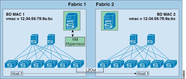


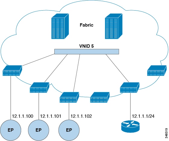
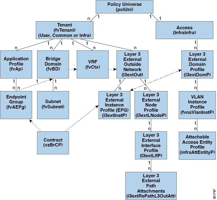


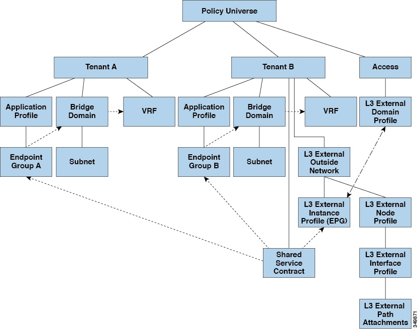


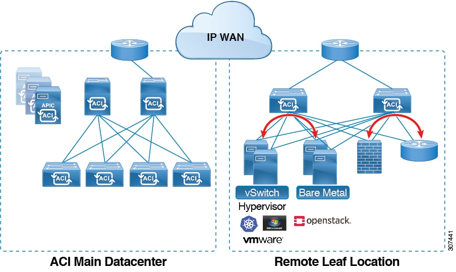


 Feedback