The documentation set for this product strives to use bias-free language. For the purposes of this documentation set, bias-free is defined as language that does not imply discrimination based on age, disability, gender, racial identity, ethnic identity, sexual orientation, socioeconomic status, and intersectionality. Exceptions may be present in the documentation due to language that is hardcoded in the user interfaces of the product software, language used based on RFP documentation, or language that is used by a referenced third-party product. Learn more about how Cisco is using Inclusive Language.
The ACI policy model
enables the specification of application requirements policies. The
APIC automatically renders policies in the
fabric infrastructure. When a user or process initiates an administrative
change to an object in the fabric, the
APIC first applies that change to the
policy model. This policy model change then triggers a change to the actual
managed endpoint. This approach is called a model-driven framework.
Policy Model Key
Characteristics
Key characteristics
of the policy model include the following:
As a model-driven
architecture, the software maintains a complete representation of the
administrative and operational state of the system (the model). The model
applies uniformly to fabric, services, system behaviors, and virtual and
physical devices attached to the network.
The logical and
concrete domains are separated; the logical configurations are rendered into
concrete configurations by applying the policies in relation to the available
physical resources. No configuration is carried out against concrete entities.
Concrete entities are configured implicitly as a side effect of the changes to
the
APIC
policy model. Concrete entities can be, but do not have to be, physical (such
as a virtual machine or a VLAN).
The system
prohibits communications with newly connected devices until the policy model is
updated to include the new device.
Network
administrators do not configure logical and physical system resources directly
but rather define logical (hardware independent) configurations and
APIC
policies that control different aspects of the system behavior.
Managed object
manipulation in the model relieves engineers from the task of administering
isolated, individual component configurations. These characteristics enable
automation and flexible workload provisioning that can locate any workload
anywhere in the infrastructure. Network-attached services can be easily
deployed, and the
APIC
provides an automation framework to manage the life cycle of those
network-attached services.
Logical
Constructs
The policy model
manages the entire fabric, including the infrastructure, authentication,
security, services, applications, and diagnostics. Logical constructs in the
policy model define how the fabric meets the needs of any of the functions of
the fabric. The following figure provides an overview of the ACI policy model
logical constructs.
Figure 1. ACI Policy
Model Logical Constructs Overview
Fabric-wide
or tenant administrators create predefined policies that contain application or
shared resource requirements. These policies automate the provisioning of
applications, network-attached services, security policies, and tenant subnets,
which puts administrators in the position of approaching the resource pool in
terms of applications rather than infrastructure building blocks. The
application needs to drive the networking behavior, not the other way around.
The Cisco ACI Policy
Management Information Model
The fabric comprises
the physical and logical components as recorded in the Management Information
Model (MIM), which can be represented in a hierarchical management information
tree (MIT). The information model is stored and managed by processes that run
on the
APIC.
Similar to the OSI Common Management Information Protocol (CMIP) and other
X.500 variants, the
APIC
enables the control of managed resources by presenting their manageable
characteristics as object properties that can be inherited according to the
location of the object within the hierarchical structure of the MIT.
Each node in the tree
represents a managed object (MO) or group of objects. MOs are abstractions of
fabric resources. An MO can represent a concrete object, such as a switch,
adapter, or a logical object, such as an application profile, endpoint group,
or fault. The following figure provides an overview of the MIT.
Figure 2. Cisco ACI
Policy Management Information Model Overview
The hierarchical structure starts with the policy universe at the
top (Root) and contains parent and child nodes. Each node in the tree is an MO
and each object in the fabric has a unique distinguished name (DN) that
describes the object and locates its place in the tree.
The following managed
objects contain the policies that govern the operation of the system:
APIC
controllers comprise a replicated synchronized clustered controller that
provides management, policy programming, application deployment, and health
monitoring for the multitenant fabric.
A tenant is a
container for policies that enable an administrator to exercise domain-based
access control. The system provides the following four kinds of tenants:
User tenants
are defined by the administrator according to the needs of users. They contain
policies that govern the operation of resources such as applications,
databases, web servers, network-attached storage, virtual machines, and so on.
The common
tenant is provided by the system but can be configured by the fabric
administrator. It contains policies that govern the operation of resources
accessible to all tenants, such as firewalls, load balancers, Layer 4 to Layer
7 services, intrusion detection appliances, and so on.
The
infrastructure tenant is provided by the system but can be configured by the
fabric administrator. It contains policies that govern the operation of
infrastructure resources such as the fabric VXLAN overlay. It also enables a
fabric provider to selectively deploy resources to one or more user tenants.
Infrastructure tenant polices are configurable by the fabric administrator.
The management
tenant is provided by the system but can be configured by the fabric
administrator. It contains policies that govern the operation of fabric
management functions used for in-band and out-of-band configuration of fabric
nodes. The management tenant contains a private out-of-bound address space for
the
APIC/fabric
internal communications that is outside the fabric data path that provides
access through the management port of the switches. The management tenant
enables discovery and automation of communications with virtual machine
controllers.
Access policies
govern the operation of switch access ports that provide connectivity to
resources such as storage, compute, Layer 2 and Layer 3 (bridged and routed)
connectivity, virtual machine hypervisors, Layer 4 to Layer 7 devices, and so
on. If a tenant requires interface configurations other than those provided in
the default link, Cisco Discovery Protocol (CDP), Link Layer Discovery Protocol
(LLDP), Link Aggregation Control Protocol (LACP), or Spanning Tree, an
administrator must configure access policies to enable such configurations on
the access ports of the leaf switches.
Fabric policies
govern the operation of the switch fabric ports, including such functions as
Network Time Protocol (NTP) server synchronization, Intermediate
System-to-Intermediate System Protocol (IS-IS), Border Gateway Protocol (BGP)
route reflectors, Domain Name System (DNS) and so on. The fabric MO contains
objects such as power supplies, fans, chassis, and so on.
Virtual Machine
(VM) domains group VM controllers with similar networking policy requirements.
VM controllers can share VLAN or Virtual Extensible Local Area Network (VXLAN)
space and application endpoint groups (EPGs). The
APIC
communicates with the VM controller to publish network configurations such as
port groups that are then applied to the virtual workloads.
Layer 4 to Layer 7
service integration life cycle automation framework enables the system to
dynamically respond when a service comes online or goes offline. Policies
provide service device package and inventory management functions.
Access,
authentication, and accounting (AAA) policies govern user privileges, roles,
and security domains of the Cisco ACI fabric.
The hierarchical
policy model fits well with the REST API interface. When invoked, the API reads
from or writes to objects in the MIT. URLs map directly into distinguished
names that ide.jpgy objects in the MIT. Any data in the MIT can be described as
a self-contained structured tree text document encoded in XML or JSON.
Tenants
A tenant (fvTenant) is a logical container for application policies that enable an administrator to exercise domain-based access control. A
tenant represents a unit of isolation from a policy perspective, but it does not represent a private network. Tenants can
represent a customer in a service provider setting, an organization or domain in an enterprise setting, or just a convenient
grouping of policies. The following figure provides an overview of the tenant portion of the management information tree (MIT).
Figure 3. Tenants
Tenants can be isolated from one another or can share resources. The primary elements that the tenant contains are filters,
contracts, outside networks, bridge domains, Virtual Routing and Forwarding (VRF) instances, and application profiles that
contain endpoint groups (EPGs). Entities in the tenant inherit its policies. VRFs are also known as contexts; each VRF can
be associated with multiple bridge domains.
Note
In the APIC GUI under the tenant navigation path, a VRF (context) is called a private network.
Tenants are logical
containers for application policies. The fabric can contain multiple tenants.
You must configure a tenant before you can deploy any Layer 4 to Layer 7
services. The ACI fabric supports IPv4, IPv6, and dual-stack configurations for
tenant networking.
VRFs
A Virtual Routing and Forwarding (VRF) object (fvCtx) or context is a tenant network (called a private network in the APIC GUI). A tenant can have multiple VRFs. A VRF is a unique Layer 3 forwarding and application policy domain. The following
figure shows the location of VRFs in the management information tree (MIT) and their relation to other objects in the tenant.
Figure 4. VRFs
A VRF defines a Layer 3 address domain. One or more bridge domains are associated with a VRF. All of the endpoints within
the Layer 3 domain must have unique IP addresses because it is possible to forward packets directly between these devices
if the policy allows it. A tenant can contain multiple VRFs. After an administrator creates a logical device, the administrator
can create a VRF for the logical device, which provides a selection criteria policy for a device cluster. A logical device
can be selected based on a contract name, a graph name, or the function node name inside the graph.
Note
In the APIC GUI, a VRF (fvCtx) is also called a "Context" or "Private Network."
Application
Profiles
An application profile (fvAp) defines the policies, services and relationships between endpoint groups (EPGs). The following figure shows the location
of application profiles in the management information tree (MIT) and their relation to other objects in the tenant.
Figure 5. Application Profiles
Application profiles
contain one or more EPGs. Modern applications contain multiple components. For
example, an e-commerce application could require a web server, a database
server, data located in a storage area network, and access to outside resources
that enable financial transactions. The application profile contains as many
(or as few) EPGs as necessary that are logically related to providing the
capabilities of an application.
EPGs can be organized
according to one of the following:
The application they provide, such as a DNS server or SAP application (see Tenant Policy Example in Cisco APIC REST API Configuration Guide).
The function they provide (such as infrastructure)
Where they are in the structure of the data center (such as DMZ)
Whatever organizing principle that a fabric or tenant administrator chooses to use
Endpoint
Groups
The endpoint group (EPG) is the most important object in the policy model. The following figure shows where application EPGs
are located in the management information tree (MIT) and their relation to other objects in the tenant.
Figure 6. Endpoint Groups
An EPG is a managed
object that is a named logical entity that contains a collection of endpoints.
Endpoints are devices that are connected to the network directly or indirectly.
They have an address (identity), a location, attributes (such as version or
patch level), and can be physical or virtual. Knowing the address of an
endpoint also enables access to all its other identity details. EPGs are fully
decoupled from the physical and logical topology. Endpoint examples include
servers, virtual machines, network-attached storage, or clients on the
Internet. Endpoint membership in an EPG can be dynamic or static.
The ACI fabric can contain the following types of EPGs:
Application endpoint group (fvAEPg)
Layer 2 external outside network instance endpoint group (l2extInstP)
Layer 3 external outside network instance endpoint group (l3extInstP)
Management endpoint groups for out-of-band (mgmtOoB) or in-band ( mgmtInB) access.
EPGs contain endpoints that have common policy requirements such as security, virtual machine mobility (VMM), QoS, or Layer
4 to Layer 7 services. Rather than configure and manage endpoints individually, they are placed in an EPG and are managed
as a group.
Policies apply to EPGs, never to individual endpoints. An EPG can be statically configured by an administrator in the APIC,
or dynamically configured by an automated system such as vCenter or OpenStack.
Note
When an EPG uses a static binding path, the encapsulation VLAN associated with this EPG must be part of a static VLAN pool.
For IPv4/IPv6 dual-stack configurations, the IP address property is contained in the fvStIp child property of the fvStCEp MO. Multiple fvStIp objects supporting IPv4 and IPv6 addresses can be added under one fvStCEp object. When upgrading ACI from IPv4-only firmware to versions of firmware that support IPv6, the existing IP property is
copied to an fvStIp MO.
Regardless of how an
EPG is configured, EPG policies are applied to the endpoints they contain.
WAN router connectivity to the fabric is an example of a configuration that uses a static EPG. To configure WAN router connectivity
to the fabric, an administrator configures an l3extInstP EPG that includes any endpoints within an associated WAN subnet. The fabric learns of the EPG endpoints through a discovery
process as the endpoints progress through their connectivity life cycle. Upon learning of the endpoint, the fabric applies
the l3extInstP EPG policies accordingly. For example, when a WAN connected client initiates a TCP session with a server within an application
(fvAEPg) EPG, the l3extInstP EPG applies its policies to that client endpoint before the communication with the fvAEPg EPG web server begins. When the client server TCP session ends and communication between the client and server terminate,
that endpoint no longer exists in the fabric.
Note
If a leaf switch is configured for static binding (leaf switches) under an EPG, the following restrictions apply:
The static binding cannot be overridden with a static path.
Interfaces in that switch cannot be used for routed external network (L3out) configurations.
Interfaces in that switch cannot be assigned IP addresses.
Virtual machine management connectivity to VMware vCenter is an example of a configuration that uses a dynamic EPG. Once the
virtual machine management domain is configured in the fabric, vCenter triggers the dynamic configuration of EPGs that enable
virtual machine endpoints to start up, move, and shut down as needed.
IP-Based EPGs
Although encapsulation-based EPGs are commonly used, IP-based EPGs are suitable in networks where there is a need for large
numbers of EPGs that cannot be supported by Longest Prefix Match (LPM) classification. IP-based EPGs do not require allocating
a network/mask range for each EPG, unlike LPM classification. Also, a unique bridge domain is not required for each IP-based
EPG. The configuration steps for an IP-based EPG are like those for configuring a virtual IP-based EPG that is used in the
Cisco AVS vCenter configuration.
Observe the following guidelines and limitations of IP-based EPGs:
IP-based EPGs are supported starting with the APIC 1.1(2x) and ACI switch 11.1(2x) releases on the following Cisco Nexus
N9K switches:
Switches with "E" on the end of the switch name, for example, N9K-C9372PX-E.
Switches with "EX" on the end of the switch name, for example, N9K-93108TC-EX.
The APIC raises a fault when you attempt to deploy IP-based EPGs on older switches that do not support them.
IP-based EPGs can be configured for specific IP addresses or subnets, but not IP address ranges.
IP-based EPGs are not supported in the following scenarios:
In combination with static EP configurations.
External, infrastructure tenant (infra) configurations will not be blocked, but they do not take effect, because there is
no Layer 3 learning in this case.
In Layer 2-only bridge domains, IP-based EPG does not take effect, because there is no routed traffic in this case. If proxy
ARP is enabled on Layer 3 bridge domains, the traffic is routed even if endpoints are in the same subnet. So IP-based EPG
works in this case.
Configurations with a prefix that is used both for shared services and an IP-based EPG.
Microsegmentation
Microsegmentation associates endpoints from multiple EPGs into a microsegmented EPG according to virtual machine attributes,
IP address, or MAC address. Virtual machine attributes include: VNic domain name, VM identifier, VM name, hypervisor identifier,
VMM domain, datacenter, operating system, or custom attribute.
Some advantages of microsegmentation include the following:
Stateless white list network access security with line rate enforcement.
Per-microsegment granularity of security automation through dynamic Layer 4 - Layer 7 service insertion and chaining.
Hypervisor agnostic microsegmentation in a broad range of virtual switch environments.
ACI policies that easily move problematic VMs into a quarantine security zone.
When combined with intra-EPG isolation for bare metal and VM endpoints, microsegmentation can provide policy driven automated
complete endpoint isolation within application tiers.
For any EPG, the ACI fabric ingress leaf switch classifies packets into an EPG according to the policies associated with the
ingress port. Microsegmented EPGs apply policies to individual virtual or physical endpoints that are derived based on the
VM attribute, MAC address, or IP address specified in the microsegmented EPG policy.
Intra-EPG Endpoint
Isolation
Intra-EPG endpoint isolation policies provide full isolation for virtual or physical endpoints; no communication is allowed
between endpoints in an EPG that is operating with isolation enforced. Isolation enforced EPGs reduce the number of EPG encapsulations
required when many clients access a common service but are not allowed to communicate with each other.
An EPG is isolation enforced for all Cisco Application Centric
Infrastructure (ACI) network domains or none. While the Cisco ACI fabric implements isolation directly to connected endpoints, switches connected to the fabric are made aware of isolation
rules according to a primary VLAN (PVLAN) tag.
Note
If an EPG is configured with intra-EPG endpoint isolation enforced, these restrictions apply:
All Layer 2 endpoint communication across an isolation enforced EPG is dropped within a bridge domain.
All Layer 3 endpoint communication across an isolation enforced EPG is dropped within the same subnet.
Preserving QoS CoS priority settings is not supported when traffic is flowing from an EPG with isolation enforced to an EPG
without isolation enforced.
BPDUs are not forwarded through EPGs with intra-EPG isolation enabled. Therefore, when you connect an external Layer 2 network
that runs spanning tree in a VLAN that maps to an isolated EPG on Cisco ACI, Cisco ACI might prevent spanning tree in the external network from detecting a Layer 2 loop. You can avoid this issue by ensuring that
there is only a single logical link between Cisco ACI and the external network in these VLANs.
Bridge Domains and
Subnets
A bridge domain (fvBD) represents a Layer 2 forwarding construct within the fabric. The following figure shows the location of bridge domains in
the management information tree (MIT) and their relation to other objects in the tenant.
Figure 7. Bridge Domains
A bridge domain must be linked to a VRF instance (also known as a context or private network). With the exception of a Layer
2 VLAN, it must have at least one subnet (fvSubnet) associated with it. The bridge domain defines the unique Layer 2 MAC address space and a Layer 2 flood domain if such flooding
is enabled. While a VRF instance defines a unique IP address space, that address space can consist of multiple subnets. Those
subnets are defined in one or more bridge domains that reference the corresponding VRF instance.
The options for a subnet under a bridge domain or under an EPG are as follows:
Public: The subnet can be exported to a routed connection.
Private: The subnet applies only within its tenant.
Shared: The subnet can be shared with and exported to multiple VRF instances in the same tenant or across tenants as part of a shared
service. An example of a shared service is a routed connection to an EPG present in another VRF instance in a different tenant.
This enables traffic to pass in both directions across VRF instances. An EPG that provides a shared service must have its
subnet configured under that EPG (not under a bridge domain), and its scope must be set to advertised externally, and shared
between VRF instances.
Note
Shared subnets must be unique across the VRF instance involved in the communication. When a subnet under an EPG provides a
Layer 3 external network shared service, such a subnet must be globally unique within the entire Cisco Application Centric
Infrastructure (ACI) fabric.
Bridge domain packet behavior can be controlled in the following ways:
Packet Type
Mode
ARP
You can enable or disable ARP Flooding; without flooding, ARP packets are sent with unicast.
Note
If the limitIpLearnToSubnets in fvBD is set, endpoint learning is limited to the bridge domain only if the IP address is in a configured subnet of the bridge
domain or an EPG subnet that is a shared service provider.
Unknown Unicast
L2 Unknown Unicast, which can be Flood or Hardware Proxy.
Note
When the bridge domain has L2 Unknown Unicast set to Flood, if an endpoint is deleted the system deletes it from both the local leaf switches as well as the remote leaf switches where
the bridge domain is deployed, by selecting Clear Remote MAC Entries. Without this feature, the remote leaf continues to have this endpoint learned until the timer expires.
Modifying the L2 Unknown Unicast setting causes traffic to bounce (go down and up) on interfaces to devices attached to EPGs associated with this bridge domain.
Unknown IP Multicast
L3 Unknown Multicast Flooding
Flood: Packets are flooded on ingress and border leaf switch nodes only. With N9K-93180YC-EX, packets are flooded on all the nodes
where a bridge domain is deployed.
Optimized: Only 50 bridge domains per leaf are supported. This limitation is not applicable for N9K-93180YC-EX.
L2 Multicast, Broadcast, Unicast
Multi-Destination Flooding, which can be one of the following:
Flood in BD: Flood in bridge domain
Flood in Encapsulation: Flood in encapsulation
Drop: Drop the packets
Note
Beginning with Cisco APIC release 3.1(1), on the Cisco Nexus 9000 series switches (with names ending with EX and FX and onwards),
the following protocols can be flooded in encapsulation or flooded in a bridge domain: OSPF/OSPFv3, BGP, EIGRP, LACP, ISIS,
IGMP, PIM, ST-BPDU, ARP/GARP, RARP, and ND.
Bridge domains can span multiple switches. A bridge domain can contain multiple subnets, but a subnet is contained within
a single bridge domain. If the bridge domain (fvBD) limitIPLearnToSubnets property is set to yes, endpoint learning will occur in the bridge domain only if the IP address is within any of the configured subnets for the
bridge domain or within an EPG subnet when the EPG is a shared service provider. Subnets can span multiple EPGs; one or more
EPGs can be associated with one bridge domain or subnet. In hardware proxy mode, ARP traffic is forwarded to an endpoint in
a different bridge domain when that endpoint has been learned as part of the Layer 3 lookup operation.
Bridge Domain Options
A bridge domain can be set to operate in flood mode for unknown unicast frames or in an optimized mode that eliminates flooding
for these frames. When operating in flood mode, Layer 2 unknown unicast traffic is flooded over the multicast tree of the
bridge domain (GIPo). For the bridge domain to operate in optimized mode you should set it to hardware-proxy. In this case,
Layer 2 unknown unicast frames are sent to the spine-proxy anycast VTEP address.
Caution
Changing from unknown unicast flooding mode to hw-proxy mode is disruptive to the traffic in the bridge domain.
If IP routing is enabled in the bridge domain, the mapping database learns the IP address of the endpoints in addition to
the MAC address.
The Layer 3 Configurations tab of the bridge domain panel allows the administrator to configure the following parameters:
Unicast Routing: If this setting is enabled and a subnet address is configured, the fabric provides the default gateway function and routes
the traffic. Enabling unicast routing also instructs the mapping database to learn the endpoint IP-to-VTEP mapping for this
bridge domain. The IP learning is not dependent upon having a subnet configured under the bridge domain.
Subnet Address: This option configures the SVI IP addresses (default gateway) for the bridge domain.
Limit IP Learning to Subnet: This option is similar to a unicast reverse-forwarding-path check. If this option is selected, the fabric will not learn
IP addresses from a subnet other than the one configured on the bridge domain.
Caution
Enabling Limit IP Learning to Subnet is disruptive to the traffic in the bridge domain.
Scaled L2 Only Mode - Legacy Mode
In Cisco Application Centric
Infrastructure (ACI), the same VLAN ID can be reused for any purpose as long as the VLAN is deployed on different leaf nodes. This allows the
Cisco ACI fabric to overcome the theoretical maximum number of VLANs 4094 as a fabric. However, to accomplish this, and also to hide
the complexity of underlying VxLAN implementation, each individual leaf node can contain smaller number of VLANs. This may
pose a problem when the density of VLANs per leaf node is required. In such a scenario, you can enable Scaled L2 Only mode, formerly known as legacy mode on the bridge domain. A bridge domain in scaled L2 only mode allows large number of VLANs
per leaf node. However, such a bridge domain has some limitations.
For the number of VLANs or bridge domains supported per leaf node with or without
scaled L2 only mode, see Verified Scalability Guide for your
specific release.
Limitations for Scaled L2 Only Mode
The following are limitations for legacy mode or scaled L2 only mode.
The bridge domain can contain only one EPG and one VLAN.
Unicast routing is not supported.
Contracts are not supported.
Dynamic VLAN allocation for VMM integration is not supported.
Service graph is not supported.
A QoS policy is not supported.
The bridge domain essentially behaves as a VLAN in standalone Cisco NX-OS.
Scaled L2 Only Mode Configuration
The following are considerations to configure a bridge domain in scaled L2 only
mode.
VLAN ID is configured on the bridge domain.
VLAN IDs configured under the EPG are overridden.
Enabling or disabling a scaled L2 only mode on an existing bridge domain will
impact service.
Cisco Application Policy Infrastructure
Controller (APIC) will automatically undeploy and redeploy the bridge domain when the VLAN ID is different from what was used prior to the
change.
When the same VLAN ID is used before and after the mode change, Cisco APIC will not automatically undeploy and redeploy the bridge domain. You must manually undeploy and redeply the bridge domain,
which can be performed by deleting and recreating the static port configuration under the EPG.
When changing the VLAN ID for scaled L2 only mode, you must first disable the
mode, then enable scaled L2 only mode with the new VLAN ID.
Disabling IP Learning per Bridge Domain
You can disable IP dataplane learning for a bridge domain. The MAC learning still occurs in the hardware, but the IP learning
only occurs from the ARP/GARP/ND processes. This functionality was introduced in the Cisco APIC 3.1 releases primarily for service graph policy-based redirect (PBR) deployments, and it has been superseded by the ability
to disable IP dataplane learning per-VRF instance (Cisco APIC release 4.0), per bridge domain subnet (Cisco APIC release 5.2), and per-EPG (Cisco APIC release 5.2). We do not recommend disabling IP learning per bridge domain and it is not supported except when used with PBR.
See the following guidelines and limitations for disabling IP learning per bridge domain:
Layer 3 multicast is not supported because the source IP address is not learned to populate the S,G information in the remote
leaf switches.
As the DL bit is set in the iVXLAN header, the MAC address is also not learned from the data path in the remote leaf switches.
It results in flooding of the unknown unicast traffic from the remote leaf switch to all leaf switches in the fabric where
this bridge domain is deployed. We recommend that you configure the bridge domain in proxy mode to overcome this situation
if endpoint dataplane learning is disabled.
ARP should be in flood mode and GARP based detection should be enabled.
When IP learning is disabled, Layer 3 endpoints are not flushed in the corresponding VRF instance. It may lead to the endpoints
pointing to the same leaf switch forever. To resolve this issue, flush all the remote IP endpoints in this VRF on all leaf
switches.
The configuration change of disabling dataplane learning on the bridge domain does not flush previously locally learned endpoints.
This limits the disruption to existing traffic flows. MAC learned endpoints age as usual if the Cisco ACI leaf switch sees no traffic with the given source MAC for longer than the endpoint retention policy.
Note
Disabling IP dataplane learning means that the endpoint IP information is not updated as a result of traffic forwarding, but
Cisco ACI can refresh the endpoint IP information with ARP/ND. This means that the aging of the local endpoints (whether they were
learned before the configuration change, or they are learned after the configuration change) differs slightly from the normal
aging and it depends also from System > System Settings > Endpoint Controls > IP Aging.
If IP Aging is disabled, traffic from a source MAC that matches
an already learned endpoint MAC, refreshes the MAC addresses information in the
endpoint table, and as a result also refreshes the IP information (this is the
same as IP dataplane learning enabled).
If IP Aging is enabled, Cisco ACI ages out endpoint IP addresses individually (this is no different from what happens with IP dataplane learning enabled),
but differently from configurations with IP dataplane learning enabled, traffic from a known source MAC and IP that matches
an already learned endpoint, refreshes the MAC address information in the endpoint table, but not the IP information.
Attachable Entity
Profile
The ACI fabric
provides multiple attachment points that connect through leaf ports to various
external entities such as bare metal servers, virtual machine hypervisors,
Layer 2 switches (for example, the Cisco UCS fabric interconnect), or Layer 3
routers (for example Cisco Nexus 7000 Series switches). These attachment points
can be physical ports, FEX ports, port channels, or a virtual port channel
(vPC) on leaf switches.
Note
When creating a VPC domain between two leaf switches, both switches must be in the same switch generation, one of the following:
Generation 1 - Cisco Nexus N9K switches without “EX” or "FX" on the end of the switch name; for example, N9K-9312TX
Generation 2 – Cisco Nexus N9K switches with “EX” or "FX" on the end of the switch model name; for example, N9K-93108TC-EX
Switches such as these two are not compatible VPC peers. Instead, use switches of the same generation.
An Attachable Entity Profile (AEP) represents a group of external entities with similar infrastructure policy requirements.
The infrastructure policies consist of physical interface policies that configure various protocol options, such as Cisco
Discovery Protocol (CDP), Link Layer Discovery Protocol (LLDP), or Link Aggregation Control Protocol (LACP).
An AEP is required to
deploy VLAN pools on leaf switches. Encapsulation blocks (and associated VLANs)
are reusable across leaf switches. An AEP implicitly provides the scope of the
VLAN pool to the physical infrastructure.
The following AEP requirements and dependencies must be accounted for in various configuration scenarios, including network
connectivity, VMM domains, and multipod configuration:
The AEP defines
the range of allowed VLANS but it does not provision them. No traffic flows
unless an EPG is deployed on the port. Without defining a VLAN pool in an AEP,
a VLAN is not enabled on the leaf port even if an EPG is provisioned.
A particular VLAN
is provisioned or enabled on the leaf port that is based on EPG events either
statically binding on a leaf port or based on VM events from external
controllers such as VMware vCenter or Microsoft Azure Service Center Virtual
Machine Manager (SCVMM).
Attached entity profiles can be associated directly with application EPGs, which deploy the associated application EPGs to
all those ports associated with the attached entity profile. The AEP has a configurable generic function (infraGeneric), which
contains a relation to an EPG (infraRsFuncToEpg) that is deployed on all interfaces that are part of the selectors that are
associated with the attachable entity profile.
A virtual machine
manager (VMM) domain automatically derives physical interface policies from the
interface policy groups of an AEP.
An override policy at
the AEP can be used to specify a different physical interface policy for a VMM
domain. This policy is useful in scenarios where a VM controller is connected
to the leaf switch through an intermediate Layer 2 node, and a different policy
is desired at the leaf switch and VM controller physical ports. For example,
you can configure LACP between a leaf switch and a Layer 2 node. At the same
time, you can disable LACP between the VM controller and the Layer 2 switch by
disabling LACP under the AEP override policy.
VLANs and EPGs
Access Policies Automate Assigning VLANs to EPGs
While tenant network policies are configured separately from fabric access policies, tenant policies are not activated unless
their underlying access policies are in place. Fabric access external-facing interfaces connect to external devices such as
virtual machine controllers and hypervisors, hosts, routers, or Fabric Extenders (FEXs). Access policies enable an administrator
to configure port channels and virtual port channels, protocols such as LLDP, CDP, or LACP, and features such as monitoring
or diagnostics.
Figure 8. Association of Endpoint Groups with Access Policies
In the policy model, EPGs are tightly coupled with VLANs. For traffic to flow, an EPG must be deployed on a leaf port with
a VLAN in a physical, VMM, L2out, L3out, or Fibre Channel domain. For more information, see Networking Domains.
In the policy model, the domain profile associated to the EPG contains the VLAN instance profile. The domain profile contains
both the VLAN instance profile (VLAN pool) and the attacheable Access Entity Profile (AEP), which are associated directly
with application EPGs. The AEP deploys the associated application EPGs to all the ports to which it is attached, and automates
the task of assigning VLANs. While a large data center could easily have thousands of active virtual machines provisioned
on hundreds of VLANs, the ACI fabric can automatically assign VLAN IDs from VLAN pools. This saves a tremendous amount of
time, compared with trunking down VLANs in a traditional data center.
VLAN Guidelines
Use the following guidelines to configure the VLANs where EPG traffic will flow.
Multiple domains can share a VLAN pool, but a single domain can only use one VLAN pool.
To deploy multiple EPGs with same VLAN encapsulation on a single leaf switch, see Per Port VLAN.
Native 802.1p and Tagged EPGs on Interfaces
When assigning Access (802.1p or Untagged) modes, follow these guidelines to ensure that devices that require untagged or
802.1p packets operate as expected when they are connected to access ports of an ACI leaf switch.
These guidelines apply to EPGs deployed on ports on a single leaf switch. When EPGs are deployed on different switches, these
restrictions do not apply.
In the APIC GUI, when you assign VLANs on ports to EPGs, you can assign one of the following VLAN modes: Trunk, Access (802.1p), or Access (Untagged).
Only one 802.1p VLAN or one untagged VLAN is allowed on a port. It can be one or the other but not both.
For generation 1 switches, if an EPG deployed on any port on a leaf switch is configured with Access (Untagged) mode, all
the ports used by the EPG should be untagged on the same leaf switch and its VPC peer (if there is one). You can have a combination
of untagged and tagged ports on generation 2 switches (with -EX, -FX, or -FX2 suffixes).
You can deploy different EPGs using (tagged) VLAN numbers in Trunk mode on the same port, with an EPG deployed on the port in Access (Untagged) mode.
There are some differences in traffic handling, depending on the switch, when a leaf switch port is associated with a single
EPG that is configured as Access (802.1p) or Access (Untagged) modes.
Generation 1 Switches
If the port is configured in Access (802.1p) mode:
On egress, if the access VLAN is the only VLAN deployed on the port, then traffic will be untagged.
On egress, if the port has other (tagged) VLANs deployed along with an untagged EPG, then traffic from that EPG is zero tagged.
On egress, for all FEX ports, traffic is untagged, irrespective of one or more VLAN tags configured on the port.
The port accepts ingress traffic that is untagged, tagged, or in 802.1p mode.
If a port is configured in Access (Untagged) mode:
On egress, the traffic from the EPG is untagged.
The port accepts ingress traffic that is untagged, tagged, or 802.1p.
Generation 2 Switches
Generation 2 switches, or later, do not distinguish between the Access (Untagged) and Access (802.1p) modes. When EPGs are deployed on Generation 2 ports configured with either Untagged or 802.1p mode:
On egress, traffic is always untagged on a node where this is deployed.
The port accepts ingress traffic that is untagged, tagged, or in 802.1p mode.
VLAN Mode Combinations on Ports: First Generation and Second Generation Hardware Running Cisco APIC Releases Prior to 3.2(3i)
VLAN Mode Combinations Supported for One EPG
EPG 1 on Port 1, with VLAN mode:
EPG 1 on different ports, the following VLAN modes are allowed:
Trunk
Trunk or 802.1p
Untagged
Untagged
802.1p
Trunk or 802.1p
VLAN Mode Combinations Supported for Multiple EPGs
EPG 1 on port 1 with VLAN mode:
EPG 1 on port 2, the following modes are allowed:
EPG 2 on port 1, the following modes are allowed:
Untagged
Untagged
Trunk
802.1p
Trunk or 802.1p
Trunk
Trunk
802.1p or Trunk
Trunk or 802.1p or untagged
VLAN Mode Combinations on Ports: Second Generation Hardware Running Cisco APIC Release 3.2(3i) or Later
VLAN Mode Combinations Supported for One EPG
EPG 1 on Port 1, with VLAN mode:
EPG 1 on different ports, the following VLAN modes are allowed:
Trunk
Trunk (tagged) or untagged or 802.1p
Untagged
Untagged or 802.1p or trunk (tagged)
802.1p
Trunk (tagged) or 802.1p or untagged
VLAN Mode Combinations Supported for Multiple EPGs
EPG 1 on port 1 with VLAN mode:
EPG 1 on port 2, the following modes are allowed:
EPG 2 on port 1, the following modes are allowed:
Untagged
Untagged or 802.1p or trunk (tagged)
Trunk (tagged)
802.1p
Trunk (tagged) or 802.1p or untagged
Trunk (tagged)
Trunk
802.1p or trunk (tagged) or untagged
Trunk (tagged) or 802.1p or untagged
Note
Certain older network interface cards (NICs) that send traffic on the native VLAN untagged, drop return traffic that is tagged
as VLAN 0. This is normally only a problem on interfaces configured as trunk ports. However, if an Attachable Entity Profile
(AEP) for an access port is configured to carry the infra VLAN, then it is treated as a trunk port, even though it is configured
as an access port. In these circumstances, packets sent on the native VLAN from the switch with Network Flow Engine (NFE)
cards will be tagged as VLAN 0, and older switch NICs may drop them. Options to address this issue include:
Removing the infra VLAN from the AEP.
Configuring "port local scope" on the port. This enables per-port VLAN definition and allows the switch equipped with NFE
to send packets on the native VLAN, untagged.
Per Port
VLAN
In ACI versions prior to the v1.1 release, a given VLAN encapsulation maps to only a single EPG on a leaf switch. If there
is a second EPG which has the same VLAN encapsulation on the same leaf switch, the ACI raises a fault.
Starting with the v1.1 release, you can deploy multiple EPGs with the same VLAN encapsulation on a given leaf switch (or
FEX), in the Per Port VLAN configuration, similar to the following diagram:
To enable deploying multiple EPGs using the same encapsulation number, on a single leaf switch, use the following guidelines:
EPGs must be associated with different bridge domains.
EPGs must be deployed on different ports.
Both the port and EPG must be associated with the same domain that is associated with a VLAN pool that contains the VLAN number.
Ports must be configured with portLocal VLAN scope.
For example, with Per Port VLAN for the EPGs deployed on ports 3 and 9 in the diagram above, both using VLAN-5, port 3 and
EPG1 are associated with Dom1 (pool 1) and port 9 and EPG2 are associated with Dom2 (pool 2).
Traffic coming from port 3 is associated with EPG1, and traffic coming from port 9 is associated with EPG2.
This does not apply to ports configured for Layer 3 external outside connectivity.
When an EPG has more than one physical domain with overlapping VLAN pools, avoid adding more
than one domain to the AEP that is used to deploy the EPG on the ports. This avoids
the risk of traffic forwarding issues.
When an EPG has only one physical domain with overlapping VLAN pool, you can associate
multiple domains with single AEP.
Only ports that have the vlanScope set to portlocal allow allocation of separate (Port, VLAN) translation entries in both ingress and egress directions. For a given port with
the vlanScope set to portGlobal (the default), each VLAN used by an EPG must be unique on a given leaf switch.
Note
Per Port VLAN is not supported on interfaces configured with Multiple Spanning Tree (MST), which requires VLAN IDs to be unique
on a single leaf switch, and the VLAN scope to be global.
Reusing VLAN Numbers Previously Used for EPGs on the Same Leaf Switch
If you have previously configured VLANs for EPGs that are deployed on a leaf switch port, and you want to reuse the same VLAN
numbers for different EPGs on different ports on the same leaf switch, use a process, such as the following example, to set
them up without disruption:
In this example, EPGs were previously deployed on a port associated with a domain including a VLAN pool with a range of 9-100.
You want to configure EPGs using VLAN encapsulations from 9-20.
Configure a new VLAN pool on a different port (with a range of, for example, 9-20).
Configure a new physical domain that includes leaf ports that are connected to firewalls.
Associate the physical domain to the VLAN pool you configured in step 1.
Configure the VLAN Scope as portLocal for the leaf port.
Associate the new EPGs (used by the firewall in this example) to the physical domain you created in step 2.
Deploy the EPGs on the leaf ports.
VLAN Guidelines for EPGs Deployed on vPCs
Figure 9. VLANs for Two Legs of a vPC
When an EPG is deployed on a vPC, it must be associated with the same domain (with the same VLAN pool) that is assigned to
the leaf switch ports on the two legs of the vPC.
In this diagram, EPG A is deployed on a vPC that is deployed on ports on Leaf switch 1 and Leaf switch 2. The two leaf switch
ports and the EPG are all associated with the same domain, containing the same VLAN pool.
Configuring Flood in Encapsulation for All Protocols and Proxy ARP Across Encapsulations
Cisco Application Centric
Infrastructure (ACI) uses the bridge domain as the Layer 2 broadcast boundary. Each bridge domain can include multiple endpoint groups (EPGs),
and each EPG can be mapped to multiple virtual or physical domains. Each EPG can also use different VLAN encapsulation pools
in each domain. Each EPG can also use different VLAN or VXLAN encapsulation pools in each domain.
Ordinarily, when you put multiple EPGs within bridge domains, broadcast flooding sends traffic to all the EPGs in the bridge
domain. Because EPGs are used to group endpoints and manage traffic to fulfill specific functions, sending the same traffic
to all the EPGs in the bridge domain is not always practical.
The flood in encapsulation feature helps to consolidate bridge domains in your network. The feature does so by enabling you
to control broadcast flooding to endpoints within the bridge domain based on the encapsulation of the virtual or physical
domain that the EPGs are associated with.
Flood in encapsulation requires the bridge domain to be configured with a subnet and with IP routing because in order to allow
communication between endpoints of different EPGs in the same bridge domain Cisco ACI performs proxy ARP.
Example of Flood in Encapsulation Use Case with VLAN Encapsulation
Flood in encapsulation is often used when the external device is using Virtual Connect Tunnel mode where one MAC address is
maintained per vNet because of VLAN-agnostic MAC learning.
Using multiple VLANs in tunnel mode can introduce a few challenges. In a typical deployment using Cisco ACI with a single tunnel, as illustrated in the following figure, there are multiple EPGs under one bridge domain. In this case,
certain traffic is flooded within the bridge domain (and thus in all the EPGs), with the risk of MAC learning ambiguities
that can cause forwarding errors.
Figure 10. Challenges of Cisco ACI with VLAN Tunnel Mode
In this topology, the blade switch (virtual connect in this example) has a single tunnel network defined that uses one uplink
to connect with the Cisco ACI leaf node. Two user VLANs, VLAN 10 and VLAN 11 are carried over this link. The bridge domain is set in flooding mode as the
servers’ gateways are outside the Cisco ACI cloud. ARP negotiations occur in the following process:
The server sends one ARP broadcast request over the VLAN 10 network.
The ARP packet travels through the tunnel network to the external server, which records the source MAC address, learned from
its downlink.
The server then forwards the packet out its uplink to the Cisco ACI leaf switch.
The Cisco ACI fabric sees the ARP broadcast packet entering on access port VLAN 10 and maps it to EPG1.
Because the bridge domain is set to flood ARP packets, the packet is flooded within the bridge domain and thus to the ports
under both EPGs as they are in the same bridge domain.
The same ARP broadcast packet comes back over the same uplink.
The blade switch sees the original source MAC address from
this uplink.
Result: The
blade switch has the same MAC address learned from both the downlink port and uplink
port within its single MAC forwarding table, causing traffic disruptions.
Recommended Solution
The flood in encapsulation option is used to limit flooding traffic inside the bridge domain to a single encapsulation. When
EPG1/VLAN X and EPG2/VLAN Y share the same bridge domain and flood in encapsulation is enabled, the encapsulation flooding
traffic does not reach the other EPG/VLAN.
Beginning with Cisco Application Policy Infrastructure
Controller (APIC) release 3.1(1), on the Cisco Nexus 9000 series switches (with names ending with EX and FX and onwards), all protocols are
flooded in encapsulation. Also, when flood in encapsulation is enabled under the bridge domain for any inter-VLAN traffic,
Proxy ARP ensures that the MAC flap issue does not occur. It also limits all flooding (ARP, GARP, and BUM) to the encapsulation.
The restriction applies for all EPGs under the bridge domain where it is enabled.
Note
Before Cisco APIC release 3.1(1), these features are not supported (proxy ARP and all protocols being included when flooding within encapsulation).
In an earlier Cisco APIC release or earlier generation switches (without EX or FX on their names), if you enable flood in encapsulation it does not
function, no informational fault is generated, but Cisco APIC decreases the health score by 1.
Note
Beginning with Cisco APIC release 3.2(5), you can configure flood in encapsulation for EPGs associated with VXLAN encapsulation. Previously, only VLANs
were supported for flood in encapsulation for virtual domains. You configure flood in encapsulation when you create or modify
a bridge domain or an EPG.
The recommended solution is to support multiple EPGs under one bridge domain by adding an external switch. This design with
multiple EPGs under one bridge domain with an external switch is illustrated in the following figure.
Figure 11. Design with Multiple EPGs Under one Bridge Domain with an External Switch
Within the same bridge domain, some EPGs can be service nodes and other EPGs can have flood in encapsulation configured. A
load balancer resides on a different EPG. The load balancer receives packets from the EPGs and sends them to the other EPGs
(There is no Proxy ARP and flood within encapsulation does not take place).
Multi-Destination Protocol Traffic
The EPG/bridge domain level broadcast segmentation is supported for the following network control protocols:
OSPF
EIGRP
LACP
IS-IS
BGP
IGMP
PIM
STP-BPDU (flooded within EPG)
ARP/GARP (controlled by ARP Proxy)
ND
Flood in Encapsulation Limitations
The following limitations apply when using flood in encapsulation for all protocols:
Flood in encapsulation does not work in ARP unicast mode.
Neighbor Solicitation (Proxy NS/ND) is not supported for this release.
Because proxy Address Resolution Protocol (ARP) is enabled implicitly, ARP traffic can go to the CPU for communication between
different encapsulations.
To ensure even distribution to different ports to process ARP traffic, enable per-port Control Plane Policing (CoPP) for ARP
with flood in encapsulation.
Flood in encapsulation is supported only in bridge domain in flood mode and ARP in flood mode. Bridge domain spine proxy mode
is not supported.
IPv4 Layer 3 multicast is not supported.
IPv6 NS/ND proxy is not supported when flood in encapsulation is enabled. As a result, the connection between two endpoints
that are under same IPv6 subnet but resident in EPGs with different encapsulation may not work.
Virtual machine migration to a different VLAN has momentary issues (60 seconds). Virtual machine migration to a different
VLAN or VXLAN has momentary issues (60 seconds).
Setting up communication between virtual machines through a firewall, as a gateway, is not recommended because if the virtual
machine IP address changes to the gateway IP address instead of the firewall IP address, then the firewall can be bypassed.
Prior releases are not supported (even interoperating between prior and current releases).
A mixed-mode topology with older-generation Application Leaf Engine (ALE) and Application Spine Engine (ASE) is not recommended
and is not supported with flood in encapsulation. Enabling them together can prevent QoS priorities from being enforced.
Flood in encapsulation is not supported for EPG and bridge domains that are extended across Cisco ACI fabrics that are part of the same Multi-Site domain. However, flood in encapsulation is still working and fully supported,
and works for EPGs or bridge domains that are locally defined in Cisco ACI fabrics, independently from the fact those fabrics may be configured for Multi-Site. The same considerations apply for EPGs
or bridge domains that are stretched between Cisco ACI fabric and remote leaf switches that are associated to that fabric.
Flood in encapsulation is not supported on EPGs where microsegmentation is configured.
If you configure the flood in encapsulation on all EPGs of a bridge domain, ensure that you configure the flood in encapsulation
on the bridge domain as well.
IGMP snooping is not supported with flood in encapsulation.
There is a condition that causes Cisco ACI to flood in the bridge domain (instead of the encapsulation) packets that are received on an EPG that is configured for flood
in encapsulation. This happens regardless of whether the administrator configured flood in encapsulation directly on the EPG
or on the bridge domain. The condition for this forwarding behavior is if the ingress leaf node has a remote endpoint for
the destination MAC address while the egress leaf node does not have a corresponding local endpoint. This can happen due to
reasons such as an interface flapping, an endpoint flush due to STP TCN, learning being disabled on the bridge domain due
to an excessive amount of moves, and so on.
In the 4.2(6o) and later 4.2(6) releases, 4.2(7m) and later 4.2(7) releases, and 5.2(1g) and later releases, this behavior
was enhanced. If the administrator enables flood in encapsulation on the bridge domain (instead of the EPG), Cisco ACI does not send out such packets on any encapsulations from downlinks facing external devices on the non-ingress (egress and
transit) leaf nodes. This new behavior prevents the packets from leaking to unexpected encapsulations. When flood in encapsulation
is enabled only at an EPG level, the non-ingress leaf node may still flood packets in the bridge domain instead of the encapsulation.
For more information, see the enhancement bug CSCvx83364.
A Layer 3 gateway must be in the Cisco ACI fabric.
Contracts
In addition to EPGs, contracts (vzBrCP) are key objects in the policy model. EPGs can only communicate with other EPGs according to contract rules. The following
figure shows the location of contracts in the management information tree (MIT) and their relation to other objects in the
tenant.
Figure 12. Contracts
An administrator uses
a contract to select the type(s) of traffic that can pass between EPGs,
including the protocols and ports allowed. If there is no contract, inter-EPG
communication is disabled by default. There is no contract required for
intra-EPG communication; intra-EPG communication is always implicitly allowed.
You can also configure contract preferred groups that enable greater control of communication between EPGs in a VRF. If most
of the EPGs in the VRF should have open communication, but a few should only have limited communication with the other EPGs,
you can configure a combination of a contract preferred group and contracts with filters to control communication precisely.
Contracts govern the
following types of endpoint group communications:
Between ACI fabric application EPGs (fvAEPg), both intra-tenant and inter-tenant
Note
In the case of a shared service mode, a contract is required for inter-tenant
communication. A contract is used to specify static routes across VRFs, even
though the tenant VRF does not enforce a policy.
Between ACI fabric
application EPGs and Layer 2 external outside network instance EPGs (l2extInstP)
Between ACI fabric
application EPGs and Layer 3 external outside network instance EPGs (l3extInstP)
Between ACI fabric
out-of-band (mgmtOoB) or in-band (mgmtInB)
management EPGs
Contracts govern the communication between EPGs that are labeled providers, consumers, or both.
EPG providers expose contracts with which a would-be consumer EPG must comply. The
relationship between an EPG and a contract can be either a provider or consumer. When an
EPG provides a contract, communication with that EPG can be initiated from other EPGs as
long as the communication complies with the provided contract. When an EPG consumes a
contract, the endpoints in the consuming EPG may initiate communication with any
endpoint in an EPG that is providing that contract.
Note
An EPG can both provide and consume the same contract. An EPG can also provide and
consume multiple contracts simultaneously.
Note
Contracts exported from a user tenant to a common tenant are not automatically available for use in other user tenants. To
share a contract across multiple user tenants and the common tenant, the contract must either be defined in the common tenant
or exported individually to each desired tenant.
Labels, Filters, Aliases, and Subjects Govern EPG Communications
Label, subject, alias and filter managed-objects enable mixing and matching among EPGs and contracts so as to satisfy various
applications or service delivery requirements. The following figure shows the location of application subjects and filters
in the management information tree (MIT) and their relation to other objects in the tenant.
Figure 13. Labels, Subjects, and Filters
Contracts can contain multiple communication rules and multiple EPGs can both consume and provide multiple contracts. Labels
control which rules apply when communicating between a specific pair of EPGs. A policy designer can compactly represent complex
communication policies and re-use these policies across multiple instances of an application. For example, the sample policy
in the Cisco Application Centric Infrastructure Fundamentals "Contract Scope Examples" chapter shows how the same contract uses labels, subjects, and filters to differentiate how communications
occur among different EPGs that require HTTP or HTTPS.
Labels, subjects, aliases and filters define EPG communications according to the following options:
Labels are managed objects with only one property: a name. Labels enable classifying which objects can and cannot communicate
with one another. Label matching is done first. If the labels do not match, no other contract or filter information is processed.
The label match attribute can be one of these values: at least one (the default), all, none, or exactly one. The Cisco Application Centric Infrastructure Fundamentals "Label Matching" chapter shows simple examples of all the label match types and their results.
Note
Labels can
be applied to a variety of provider and consumer managed objects, including
EPGs, contracts, bridge domains, DHCP relay policies, and DNS policies. Labels
do not apply across object types; a label on an application EPG has no
relevance to a label on a bridge domain.
Labels determine
which EPG consumers and EPG providers can communicate with one another. Label
matching determines which subjects of a contract are used with a given EPG
provider or EPG consumer of that contract.
The two types of
labels are as follows:
Subject labels
that are applied to EPGs. Subject label matching enables EPGs to choose a
subset of the subjects in a contract.
Provider/consumer labels that are applied to EPGs.
Provider/consumer label matching enables consumer EPGs to choose their provider
EPGs and vice versa.
Aliases are alternative names you can apply to objects, which can be changed, unlike the name.
Filters are Layer
2 to Layer 4 fields, TCP/IP header fields such as Layer 3 protocol type, Layer
4 ports, and so forth. According to its related contract, an EPG provider
dictates the protocols and ports in both the in and out directions. Contract
subjects contain associations to the filters (and their directions) that are
applied between EPGs that produce and consume the contract.
Note
When a contract filter match type is All, best practice is to use the VRF unenforced mode. Under certain circumstances, failure to follow these guidelines results
in the contract not allowing traffic among EPGs in the VRF.
Subjects are
contained in contracts. One or more subjects within a contract use filters to
specify the type of traffic that can be communicated and how it occurs. For
example, for HTTPS messages, the subject specifies the direction and the
filters that specify the IP address type (for example, IPv4), the HTTP
protocol, and the ports allowed. Subjects determine if filters are
unidirectional or bidirectional. A unidirectional filter is used in one
direction. Unidirectional filters define in or out communications but not the
same for both. Bidirectional filters are the same for both; they define both in
and out communications.
Configuring Contract or Subject Exceptions for Contracts
In Cisco APIC Release 3.2(1), contracts between EPGs are enhanced to enable denying a subset of contract providers or consumers from participating
in the contract. Inter-EPG contracts and Intra-EPG contracts are supported with this feature.
You can enable a provider EPG to communicate with all consumer EPGs except those that match criteria configured in a subject
or contract exception. For example, if you want to enable an EPG to provide services to all EPGs for a tenant, except a subset,
you can enable those EPGs to be excluded. To configure this, you create an exception in the contract or one of the subjects
in the contract. The subset is then denied access to providing or consuming the contract.
Labels, counters, and permit and deny logs are supported with contracts and subject exceptions.
To apply an exception to all subjects in a contract, add the exception to the contract. To apply an exception only to a single
subject in the contract, add the exception to the subject.
When adding filters to subjects, you can set the action of the filter (to permit or deny objects that match the filter criteria).
Also for Deny filters, you can set the priority of the filter. Permit filters always have the default priority. Marking the subject-to-filter relation to deny automatically applies to each pair
of EPGs where there is a match for the subject. Contracts and subjects can include multiple subject-to-filter relationships
that can be independently set to permit or deny the objects that match the filters.
Exception Types
Contract and subject exceptions can be based on the following types and include regular expressions, such as the * wildcard:
Exception criteria exclude these objects as defined in the Consumer Regex and Provider Regex fields
The example assumes that multiple EPGs exist, with names starting with EPGPa, and they should all be denied as consumers for the contract provided by EPg03
The example excludes objects marked with the red tag from consuming and those marked with the green tag from participating in the contract.
Taboos
While the normal
processes for ensuring security still apply, the ACI policy model aids in
assuring the integrity of whatever security practices are employed. In the ACI
policy model approach, all communications must conform to these conditions:
Communication is
allowed only based on contracts, which are managed objects in the model. If
there is no contract, inter-EPG communication is disabled by default.
No direct access
to the hardware; all interaction is managed through the policy model.
Taboo contracts can be used to deny specific traffic that is otherwise allowed by contracts. The traffic to be dropped matches
a pattern (such as, any EPG, a specific EPG, or traffic matching a filter). Taboo rules are unidirectional, denying any matching
traffic coming toward an EPG that provides the contract.
With Cisco APIC Release 3.2(x) and switches with names that end in EX or FX, you can alternatively use a subject Deny action
or Contract or Subject Exception in a standard contract to block traffic with specified patterns.
About Contract Inheritance
To streamline associating contracts to new EPGs, you can now enable an EPG to inherit all the (provided and consumed) contracts
associated directly to another EPG in the same tenant. Contract inheritance can be configured for application, microsegmented,
L2Out, and L3Out EPGs.
With Release 3.x, you can also configure contract inheritance for Inter-EPG contracts, both provided and consumed. Inter-EPG
contracts are supported on Cisco Nexus 9000 Series switches with EX or FX at the end of their model name or later models.
You can enable an EPG to inherit all the contracts associated directly to another EPG, using the APIC GUI, NX-OS style CLI,
and the REST API.
Figure 14. Contract Inheritance
In the diagram above, EPG A is configured to inherit Provided-Contract 1 and 2 and Consumed-Contract 3 from EPG B (contract
master for EPG A).
Use the following guidelines when configuring contract inheritance:
Contract inheritance can be configured for application, microsegmented (uSeg), external L2Out EPGs, and external L3Out EPGs.
The relationships must be between EPGs of the same type.
Both provided and consumed contracts are inherited from the contract master when the relationship is established.
Contract masters and the EPGs inheriting contracts must be within the same tenant.
Changes to the masters’ contracts are propagated to all the inheritors. If a new contract is added to the master, it is also
added to the inheritors.
An EPG can inherit contracts from multiple contract masters.
Contract inheritance is only supported to a single level (cannot be chained) and a contract master cannot inherit contracts.
Labels with contract inheritance is supported. When EPG A inherits a contract from EPG B, if different subject labels are
configured under EPG A and EPG B, APIC uses the label configured under EPG B for the contract inherited from EPG B. APIC uses the label configured under EPG A for the contract where EPG A is directly involved.
Whether an EPG is directly associated to a contract or inherits a contract, it consumes entries in TCAM. So contract scale
guidelines still apply. For more information, see the Verified Scalability Guide for your release.
vzAny security contracts and taboo contracts are not supported.
Beginning in Cisco APIC releases 5.0(1) and 4.2(6), contract inheritance with a service graph is supported if the contract and EPGs are in the same
tenant.
For information about configuring Contract Inheritance and viewing inherited and standalone contracts, see Cisco APIC Basic Configuration Guide.
About Contract Preferred Groups
There are two types of policy enforcements available for EPGs in a VRF with a contract preferred group configured:
Included EPGs: EPGs can freely communicate with each other without contracts, if they have membership in a contract preferred
group. This is based on the source-any-destination-any-permit default rule.
Excluded EPGs: EPGs that are not members of preferred groups require contracts to communicate with each other. Otherwise,
the default source-any-destination-any-deny rule applies.
The contract preferred group feature enables greater control of communication between EPGs in a VRF. If most of the EPGs in
the VRF should have open communication, but a few should only have limited communication with the other EPGs, you can configure
a combination of a contract preferred group and contracts with filters to control inter-EPG communication precisely.
EPGs that are excluded from the preferred group can only communicate with other EPGs if there is a contract in place to override
the source-any-destination-any-deny default rule.
Figure 15. Contract Preferred Group Overview
Limitations
The following limitations apply to contract preferred groups:
In topologies where an L3Out and application EPG are configured in a Contract Preferred Group, and the EPG is deployed only
on a VPC, you may find that only one leaf switch in the VPC has the prefix entry for the L3Out. In this situation, the other
leaf switch in the VPC does not have the entry, and therefore drops the traffic.
To workaround this issue, you can do one of the following:
Disable and reenable the contract group in the VRF
Delete and recreate the prefix entries for the L3Out EPG
Also, where the provider or consumer EPG in a service graph contract is included in a contract group, the shadow EPG can not
be excluded from the contract group. The shadow EPG will be permitted in the contract group, but it does not trigger contract
group policy deployment on the node where the shadow EPG is deployed. To download the contract group policy to the node, you
deploy a dummy EPG within the contract group .
Due to CSCvm63145, an EPG in a Contract Preferred Group can consume a shared
service contract, but cannot be a provider for a shared service contract
with an L3Out EPG as consumer.
Optimize Contract Performance
Starting with Cisco APIC, Release 3.2, you can configure bidirectional contracts that support more efficient hardware TCAM
storage of contract data. With optimization enabled, contract statistics for both directions are aggregated.
TCAM Optimization is supported on the second generation Cisco Nexus 9000 Series top of rack (TOR) switches, which are those
with suffixes of EX, FX, and FX2, and later (for example, N9K-C93180LC-EX or N9K-C93180YC-FX).
To configure efficient TCAM contract data storage, you enable the following options:
Mark the contracts to be applied in both directions between the provider and consumer.
For filters with IP TCP or UDP protocols, enable the reverse port option.
When configuring the contract subjects, select the Enable Policy Compression directive, which adds the no_stats option to the action attribute of the actrl:Rule managed object.
Limitations
With the Enable Policy Compression (no_stats) option selected, per-rule statistics are lost. However, combined rule statistics for both directions are present in the
hardware statistics.
After upgrading to Cisco APIC 3.2(1), to add the no_stats option to a pre-upgrade contract subject (with filters or filter entries), you must delete the contract subject and reconfigure
it with the Enable Policy Compression directive. Otherwise, compression does not occur.
For each contract with a bi-directional subject filter, Cisco NX-OS creates 2 rules:
A rule with an sPcTag and dPcTag that is marked direction=bi-dir, which is programmed in hardware
A rule marked with direction=uni-dir-ignore which is not programmed
Rules with the following settings are not compressed:
Rules with priority other than fully_qual
Opposite rules (bi-dir and uni-dir-ignore marked) with non-identical properties, such as action including directives, prio, qos or markDscp
Rule with Implicit or implarp filters
Rules with the actions Deny, Redir, Copy, or Deny-log
The following MO query output shows the two rules for a contract, that is considered for compression:
The vzAny managed object provides a convenient way of associating all endpoint groups (EPGs) in a Virtual Routing and Forwarding (VRF)
instance to one or more contracts (vzBrCP), instead of creating a separate contract relation for each EPG.
In the Cisco ACI fabric, EPGs can only communicate with other EPGs according to contract rules. A relationship between an
EPG and a contract specifies whether the EPG provides the communications defined by the contract rules, consumes them, or
both. By dynamically applying contract rules to all EPGs in a VRF, vzAny automates the process of configuring EPG contract relationships. Whenever a new EPG is added to a VRF, vzAny contract rules
automatically apply. The vzAny one-to-all EPG relationship is the most efficient way of applying contract rules to all EPGs in a VRF.
Note
In the APIC GUI under tenants, a VRF is also known as a private network (a network
within a tenant) or a context.
In the case of shared services, you must define the provider EPG shared subnet
under the EPG in order to properly derive the pcTag (classification) of the destination
from the consumer (vzAny) side. If you are migrating from a BD-to-BD shared services
configuration, where both the consumer and provider subnets are defined under bridge
domains, to vzAny acting as a shared service consumer, you must take an extra
configuration step where you add the provider subnet to the EPG with the shared flags at
minimum.
Note
If you add the EPG subnet as a duplicate of the defined BD subnet, ensure that both
definitions of the subnet always have the same flags defined. Failure to do so can
result in unexpected fabric forwarding behavior.
To use vzAny, navigate to Tenants > tenant-name > Networking > VRFs > vrf-name > EPG Collection for VRF.
About Copy Services
Unlike SPAN that duplicates all of the traffic, the Cisco Application Centric
Infrastructure (ACI) copy services feature enables selectively copying portions of the traffic between endpoint groups, according to the specifications
of the contract. Broadcast, unknown unicast and multicast (BUM), and control plane traffic that are not covered by the contract
are not copied. In contrast, SPAN copies everything out of endpoint groups, access ports or uplink ports. Unlike SPAN, copy
services do not add headers to the copied traffic. Copy service traffic is managed internally in the switch to minimize impact
on normal traffic forwarding.
A copy service is configured as part of a Layer 4 to Layer 7 service graph template that specifies a copy cluster as the destination
for the copied traffic. A copy service can tap into different hops within a service graph. For example, a copy service could
select traffic between a consumer endpoint group and a firewall provider endpoint group, or between a server load balancer
and a firewall. Copy clusters can be shared across tenants.
Copy services require you to do the following tasks:
Identify the source and destination endpoint groups.
Configure the contract that specifies what to copy according to the subject and what is allowed in the contract filter.
Configure Layer 4 to Layer 7 copy devices that identify the target devices and specify the ports where they attach.
Use the copy service as part of a Layer 4 to Layer 7 service graph template.
Configure a device selection policy that specifies which device will receive the traffic from the service graph. When you
configure the device selection policy, you specify the contract, service graph, copy cluster, and cluster logical interface
that is in copy device.
Outside
Networks
Outside network policies control connectivity to the outside. A tenant can contain multiple outside network objects. The following
figure shows the location of outside networks in the management information tree (MIT) and their relation to other objects
in the tenant.
Figure 16. Outside Networks
Outside network
policies specify the relevant Layer 2 (l2extOut) or Layer 3
(l3extOut)
properties that control communications between an outside public or private
network and the ACI fabric. External devices, such as routers that connect to
the WAN and enterprise core, or existing Layer 2 switches, connect to the front
panel interface of a leaf switch. The leaf switch that provides such
connectivity is known as a border leaf. The border leaf switch interface that
connects to an external device can be configured as either a bridged or routed
interface. In the case of a routed interface, static or dynamic routing can be
used. The border leaf switch can also perform all the functions of a normal
leaf switch.
Managed Object
Relations and Policy Resolution
Relationship managed objects express the relation between managed object instances that do not
share containment (parent-child) relations. MO relations are established between the
source MO and a target MO in one of the following two ways:
An explicit relation (fvRsPathAtt) defines a relationship based
on the target MO distinguished name (DN).
A named relation defines a relationship based on the target MO name.
The dotted lines in
the following figure shows several common MO relations.
Figure 17. MO
Relations
For example, the dotted line between the EPG and the bridge domain defines the relation between those two MOs. In this figure,
the EPG (fvAEPg) contains a relationship MO (fvRsBD) that is named with the name of the target bridge domain MO (fvBD). For example, if production is the bridge domain name (tnFvBDName=production), then the relation name would be production (fvRsBdName=production).
In the case of policy resolution based on named relations, if a target MO with a matching name is not found in the current
tenant, the ACI fabric tries to resolve in the common tenant. For example, if the user tenant EPG contained a relationship
MO targeted to a bridge domain that did not exist in the tenant, the system tries to resolve the relationship in the common
tenant. If a named relation cannot be resolved in either the current tenant or the common tenant, the ACI fabric attempts
to resolve to a default policy. If a default policy exists in the current tenant, it is used. If it does not exist, the ACI
fabric looks for a default policy in the common tenant. Bridge domain, VRF, and contract (security policy) named relations
do not resolve to a default.
Default
Policies
The initial values of the APIC default policies values are taken from the concrete model that is loaded in the switch. A fabric
administrator can modify default policies.
Warning
Default policies can be modified or deleted. Deleting a default policy can result in a policy resolution process to complete
abnormally.
The ACI fabric
includes default policies for many of its core functions. Examples of default
policies include the following:
Bridge domain (in
the common tenant)
Layer 2 and Layer
3 protocols
Fabric
initialization, device discovery, and cabling detection
Storm control and
flooding
Virtual port
channel
Endpoint retention
for caching and aging of learned endpoints in switch buffers
Loop detection
Monitoring and
statistics
Note
To avoid confusion when implementing configurations that use default policies, document changes made to default policies.
Be sure there are no current or future configurations that rely on a default policy before deleting a default policy. For
example, deleting a default firmware update policy could result in a problematic future firmware update.
Note
The instrumentation policy is required when the default VRF or bridge domain is present in the user tenant and the VRF or
bridge domain association is empty in bridge domain / EPG
When the ACI fabric is upgraded, the existing policy default values persist, even if the default value changes in the newer
release. When the node connects to the APIC for the first time, the node registers itself with APIC which pushes all the default
policies to the node. Any change in the default policy is pushed to the node.
A default policy serves multiple purposes:
Allows a fabric administrator to override the default values in the model.
If an administrator does not provide an explicit policy, the APIC applies the default policy. An administrator can create
a default policy and the APIC uses that unless the administrator provides any explicit policy.
For example, according to actions the administrator does or does not take, the APIC will do the following:
Because the administrator does not specify the LLDP policy for the selected ports, the APIC applies the default LLDP interface
policy for the ports specified in the port selector.
If the administrator removes a port from a port selector, the APIC applies the default policies to that port. In this example,
if the administrator removes port 1/15 from the port selector, the port is no longer part of the port channel and the APIC
applies all the default policies to that port.
The following
scenarios describe common policy resolution behavior:
A configuration explicitly refers to the default policy: if a default policy exists in the current tenant, it is used. Otherwise,
the default policy in tenant common is used.
A configuration refers to a named policy (not default) that does not exist in the current tenant or in tenant common: if the
current tenant has a default policy, it is used. Otherwise, the default policy in tenant common is used.
Note
This does not apply to a bridge domain or a VRF (private network) in a tenant.
A configuration does not refer to any policy name: if a default policy exists in the current tenant, it is used. Otherwise,
the default policy in tenant common is used.
Note
For bridge domains and VRFs, this only applies if the connectivity instrumentation policy (fvConnInstrPol) in the common tenant has the appropriate bridge domain or VRF flag set. This prevents unintended EPGs from being deployed in tenant common subnets.
The policy model specifies that an object is using another policy by having a relation managed object (MO) under that object
and that relation MO refers to the target policy by name. If this relation does not explicitly refer to a policy by name,
then the system will try to resolve a policy called default. Bridge domains (BD) and VRFs (Ctx) are exceptions to this rule.
An endpoint group (EPG) has a relation to a BD (fvRsBd) that has a property called tnFvBDName. If this is not set (tnVfBDName=""), the connectivity instrumentation policy (fvConnInstrPol) derives the behavior for this case. This policy applies for all EPG cases (VMM, baremetal, l2ext, l3ext). The instrumentation
policy uses the bdctrl property to control whether the default BD policy will be used and the ctxCtrl property to control whether the default VRF (Ctx) policy will be used. The following options are the same for both:
do not instrument: the leaf switch will not use the default policy.
instrument-and-no-route: instrument the policy and do not enable routing.
instrument-and-route: instrument the policy and enable routing.
Trans Tenant EPG
Communications
EPGs in one tenant can
communicate with EPGs in another tenant through a contract interface contained
in a shared tenant. The contract interface is an MO that can be used as a
contract consumption interface by the EPGs that are contained in different
tenants. By associating to an interface, an EPG consumes the subjects
represented by the interface to a contract contained in the shared tenant.
Tenants can participate in a single contract, which is defined at some third
place. More strict security requirements can be satisfied by defining the
tenants, contract, subjects, and filter directions so that tenants remain
completely isolated from one another.
Follow these
guidelines when configuring shared services contracts:
When a contract
is configured between in-band and out-of-band EPGs, the following restrictions
apply:
Both EPGs should be in the same VRF (context).
Filters apply
in the incoming direction only.
Layer 2
filters are not supported.
QoS does not
apply to in-band Layer 4 to Layer 7 services.
Management statistics are not available.
Shared
services for CPU-bound traffic are not supported.
Contracts are
needed for inter-bridge domain traffic when a private network is unenforced.
Prefix-based EPGs are not supported. Shared Services are not supported for a Layer 3 external outside network. Contracts
provided or consumed by a Layer 3 external outside network need to be consumed or provided by EPGs that share the same Layer
3 VRF.
A shared service
is supported only with non-overlapping and non-duplicate subnets. When
configuring subnets for shared services, follow these guidelines:
Configure the
subnet for a shared service provider under the EPG, not under the bridge
domain.
Subnets configured under an EPG that share the same VRF must be disjointed and must not overlap.
Subnets leaked from one VRF to another must be disjointed and must not overlap.
Subnets advertised from multiple consumer networks into a VRF or vice versa must be disjointed and must not overlap.
Note
If two consumers are mistakenly configured with the same subnet, recover from this condition by removing the subnet configuration
for both, then reconfigure the subnets correctly.
Do not configure a shared service with AnyToProv in the provider VRF. The APIC rejects this configuration and raises a fault.
The private
network of a provider cannot be in unenforced mode while providing a shared
service.
Tags
Object tags simplify
API operations. In an API operation, an object or group of objects can be
referenced by the tag name instead of by the distinguished name (DN). Tags are
child objects of the item they tag; besides the name, they have no other
properties.
Use a tag to assign a descriptive name to a group of objects. The same
tag name can be assigned to multiple objects. Multiple tag names can be
assigned to an object. For example, to enable easy searchable access to all web
server EPGs, assign a web server tag to all such EPGs. Web server EPGs
throughout the fabric can be located by referencing the web server tag.
About APIC Quota Management Configuration
Starting in the Cisco Application Policy Infrastructure
Controller (APIC) Release 2.3(1), there are limits on number of objects a tenant admin can configure. This enables the admin to limit what
managed objects that can be added under a given tenant or globally across tenants.
This feature is useful when you want to limit any tenant or group of tenants from exceeding ACI maximums per leaf or per fabric or unfairly consuming a majority of available resources, potentially affecting other tenants
on the same fabric.


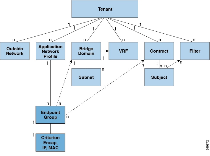


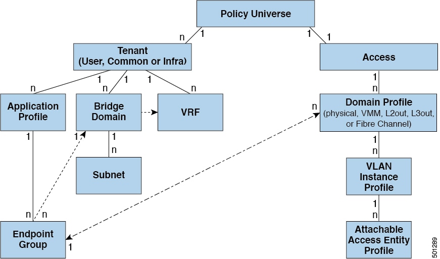
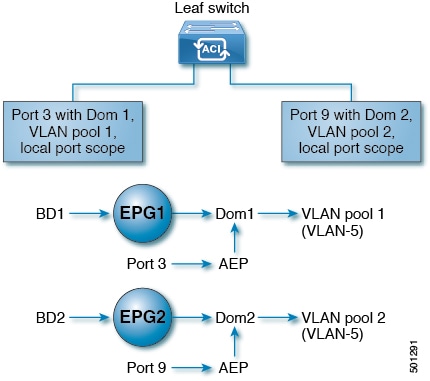
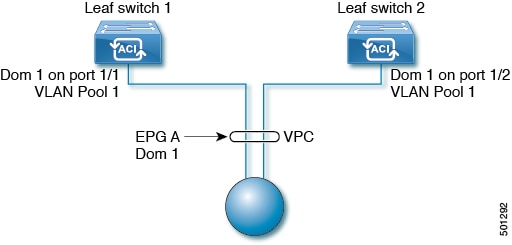


 Feedback