Configuring Infra

This chapter contains the following sections:

Configuring Infra Prerequisites and Guidelines

The following sections describe the steps necessary to configure the general as well as site-specific fabric Infra settings.

Before you proceed with Infra configuration, you must have configured and added the sites as described in previous sections, which includes:

  • Configuring each site's fabric access policies.

  • Configuring direct communication and routable subnets for sites with remote leaf switches.

In addition, keep in mind the following:

  • Any infrastructure changes such as adding and removing spine switches or spine node ID changes require a Multi-Site fabric connectivity information refresh described in the Refreshing Site Connectivity Information as part of the general Infra configuration procedures.

  • The Overlay Unicast TEP, Overlay Multicast TEP, and BGP-EVPN Router-IDs IP addresses assigned on the Orchestrator should not be taken from the address space of the original fabric's Infra TEP pool or from the 0.x.x.x range.

Configuring Infra: General Settings

This section describes how to configure general Infra settings for all the sites.

Procedure


Step 1

Log in to the Cisco ACI Multi-Site Orchestrator GUI.

Step 2

In the Main menu, click Sites.

Step 3

In the Sites view, click Configure Infra.

Step 4

In the left pane, under Settings, click General Settings.

Step 5

From the BGP Peering Type dropdown, choose either full-mesh or route-reflector.

The route-reflector option is effective only when all sites are part of the same BGP Autonomous System (AS).

Step 6

In the Keepalive Interval (Seconds) field, enter the keep alive interval seconds.

We recommend keeping the default value.

Step 7

In the Hold Interval (Seconds) field, enter the hold interval seconds.

We recommend keeping the default value.

Step 8

In the Stale Interval (Seconds) field, enter stale interval seconds.

We recommend keeping the default value.

Step 9

Choose whether you want to turn on the Graceful Helper option.

Step 10

In the Maximum AS Limit field, enter the maximum AS limit.

Step 11

In the BGP TTL Between Peers field, enter the BGP TTL between peers.


Refreshing Site Connectivity Information

Any infrastructure changes, such as adding and removing spines or changing spine node IDs, require a Multi-Site fabric connectivity site refresh. This section describes how to pull up-to-date connectivity information directly from each site's APIC.

Procedure


Step 1

Log in to the Cisco ACI Multi-Site Orchestrator GUI.

Step 2

In the Main menu, select Infrastructure > Infra Configuration.

Step 3

In the top right of the main Infra Configuration view, click the Configure Infra button.

Step 4

In the left pane, under Sites, select a specific site.

Step 5

In the main window, click the Reload Site Data button to pull fabric information from the APIC.

Step 6

(Optional) In the Confirmation dialog, check the box if you want to remove configuration for decommissioned spine switch nodes.

If you choose to enable this checkbox, all configuration info for any currently decommissioned spine switches will be removed from the database.

Step 7

Finally, click Yes to confirm and load the connectivity information.

This will discover any new or removed spines and all site-related fabric connectivity will be re-imported from the APIC.

Note


After you upgrade the Cisco Cloud APIC to Release 5.1(2), a CSR is assigned a private IP address from a private pool of addresses by Cloud APIC for BGP connectivity. Accordingly, in MSO, the BGP EVPN peer IP address for the CSR is updated and cross programmed. This update for a CSR can take up to 30 minutes. If more CSRs are added in Cloud APIC, then click Reload Site Data and Deploy on the Fabric Connectivity Infra screen in MSO.


Configuring Infra: On-Premises Site Settings

This section describes how to configure site-specific Infra settings for on-premises sites.

Procedure


Step 1

Log in to the Cisco ACI Multi-Site Orchestrator GUI.

Step 2

In the Main menu, select Infrastructure > Infra Configuration.

Step 3

In the top right of the main pane, click Configure Infra.

Step 4

In the left pane, under Sites, select a specific on-premises site.

Step 5

In the right <Site> Settings pane, enable the ACI Multi-Site knob to manage the site from the Orchestrator.

Step 6

(Optional) Enable the CloudSec Encryption knob encryption for the site.

CloudSec Encryption provides inter-site traffic encryption. The "Infrastructure Management" chapter in the Cisco ACI Multi-Site Configuration Guide covers this feature in detail.

Step 7

Specify the Overlay Multicast TEP.

This address is used for the inter-site L2 BUM and L3 multicast traffic. This IP address is deployed on all spine switches that are part of the same fabric, regardless of whether it is a single pod or multi-pod fabric.

Step 8

Specify the BGP Autonomous System Number.

Step 9

Specify the BGP Password.

Step 10

Specify the OSPF Area ID.

When configuring the Multi-Site infra OSPF details, we recommend that you use OSPF Area 0. If you use an Area ID other than 0, in the next step configure it as a regular OSPF area type and not a stub area type.

Step 11

Select the OSPF Area Type from the dropdown menu.

The OSPF area type can be one of the following:

  • nssa

  • regular

  • stub

Step 12

Select the external routed domain from the dropdown menu.

Choose an external router domain that you have created in the APIC GUI.

Step 13

Configure OSPF settings for the site.

You can either click an existing policy (for example, msc-ospf-policy-default ) to modify it or click +Add Policy to add a new OSPF policy. Then in the Add/Update Policy window, specify the following:

  • In the Policy Name field, enter the policy name.

  • In the Network Type field, choose either broadcast, point-to-point, or unspecified.

    The default is broadcast.

  • In the Priority field, enter the priority number.

    The default is 1.

  • In the Cost of Interface field, enter the cost of interface.

    The default is 0.

  • From the Interface Controls dropdown menu, choose one of the following:

    • advertise-subnet

    • bfd

    • mtu-ignore

    • passive-participation

  • In the Hello Interval (Seconds) field, enter the hello interval in seconds.

    The default is 10.

  • In the Dead Interval (Seconds) field, enter the dead interval in seconds.

    The default is 40.

  • In the Retransmit Interval (Seconds) field, enter the retransmit interval in seconds.

    The default is 5.

  • In the Transmit Delay (Seconds) field, enter the transmit delay in seconds.

    The default is 1.

Step 14

(Optional) Configure SR-MPLS settings for the site.

If the site is connected via an MPLS network, enable the SR-MPLS Connectivity knob and provide the Segment Routing global block (SRGB) range.

The Segment Routing Global Block (SRGB) is the range of label values reserved for Segment Routing (SR) in the Label Switching Database (LSD). These values are assigned as segment identifiers (SIDs) to SR-enabled nodes and have global significance throughout the domain.

The default range is 16000-23999.

If you enable MPLS connectivity for the site, you will need to configure additional settings as described in Configuring Infra: MPLS L3Out Settings.


Configuring Infra: Cloud Site Settings

This section describes how to configure site-specific Infra settings for Cloud APIC sites.

Procedure


Step 1

Log in to the Cisco ACI Multi-Site Orchestrator GUI.

Step 2

In the Main menu, select Infrastructure > Infra Configuration.

Step 3

In the top right of the main pane, click Configure Infra.

Step 4

In the left pane, under Sites, select a specific cloud site.

Most of the information in the cloud site area is automatically populated and cannot be changed, with the exception of the BGP password field.

Step 5

In the right <Site> Settings pane, enable the ACI Multi-Site knob to manage the site from the Orchestrator.

Step 6

Specify the BGP Password.


Configuring Infra: Pod Settings

This section describes how to configure pod-specific settings in each site.

Procedure


Step 1

Log in to the Cisco ACI Multi-Site Orchestrator GUI.

Step 2

In the Main menu, click Sites.

Step 3

In the Sites view, click Configure Infra.

Step 4

In the left pane, under Sites, select a specific site.

Step 5

In the main window, select a pod.

Step 6

In the right POD Properties pane, add the Overlay Unicast TEP for the POD.

This IP address is deployed on all spine switches that are part of the same pod and used for intersite known unicast traffic.

Step 7

Click +Add TEP Pool to add a routable TEP pool.

The routable TEP pools are used for public IP addresses for inter-site connectivity.

Step 8

Repeat the procedure for every pod in the site.


Configuring Infra: Spine Switches

This section describes how to configure spine switches in each site for Cisco ACI Multi-Site.

Procedure


Step 1

Log in to the Cisco ACI Multi-Site Orchestrator GUI.

Step 2

In the Main menu, click Sites.

Step 3

In the Sites view, click Configure Infra.

Step 4

In the left pane, under Sites, select a specific site.

Step 5

In the main window, select a spine switch within a pod.

Step 6

In the right <Spine> Settings pane, click +Add Port.

Step 7

In the Add Port window, enter the following information:

  • In the Ethernet Port ID field, enter the port ID, for example 1/29.

  • In the IP Address field, enter the IP address/netmask.

    The Orchestrator creates a sub-interface with VLAN 4 with the specified IP ADDRESS under the specified PORT.

  • In the MTU field, enter the MTU. You can specify either inherit or a value between 576 and 9000.

    MTU of the spine port should match MTU on IPN side.

  • In the OSPF Policy field, choose the OSPF policy for the switch that you have configured in Configuring Infra: On-Premises Site Settings.

    OSPF settings in the OSPF policy you choose should match on IPN side.

  • For OSPF Authentication, you can pick either none or one of the following:

    • MD5

    • Simple

Step 8

Enable BGP Peering knob.

In a single Pod fabric with more than two spine switches, BGP peering should only be enabled on a pair (for redundancy) of spine switches called BGP Speakers. All other spine switches should have BGP peering disabled and will function as BGP Forwarders.

In a Multi-Pod fabric BGP peering should only be enabled on a couple of BGP speaker spine switches, each deployed in a different Pod. All other spines switches should have BGP peering disabled and function as BGP forwarders.

Step 9

In the BGP-EVPN Router-ID field, provide the IP address used for BGP-eVPN session between sites.

Step 10

Repeat the procedure for every spine switch.


Configuring Infra: MPLS L3Out Settings

Starting with Orchestrator Release 3.0(1) and APIC Release 5.0(1), the Multi-Site architecture supports APIC sites connected via MPLS networks.

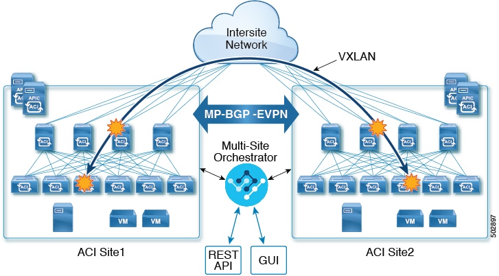
In a typical Multi-Site deployment, traffic between sites is forwarded over an intersite network (ISN) via VXLAN encapsulation:

Figure 1. Multi-Site and ISN

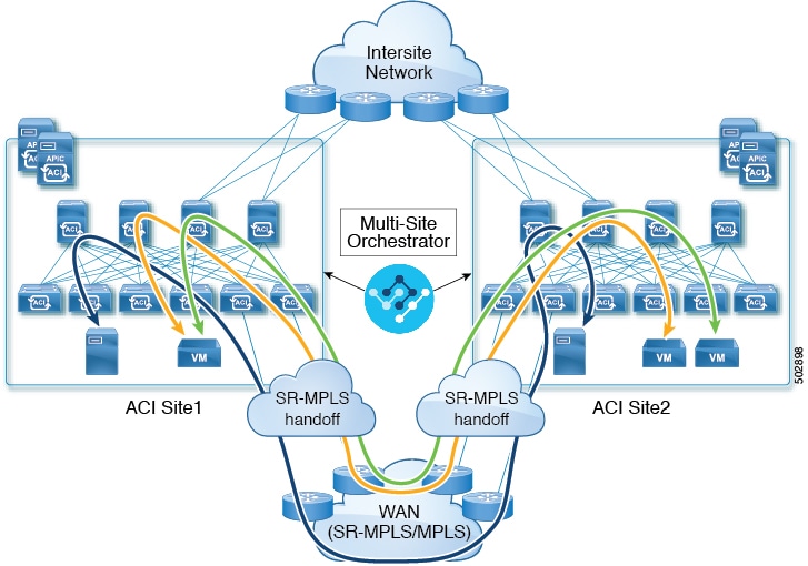
With Release 3.0(1), MPLS network can be used in addition to or instead of the ISN allowing inter-site L3Out communication via WAN:

Figure 2. Multi-Site and MPLS

The following sections describe guidelines, limitations, and configurations specific to managing Schemas that are deployed to these sites from the Multi-Site Orchestrator. Detailed information about MPLS hand off, supported individual site topologies (such as remote leaf support), and policy model is available in the Cisco APIC Layer 3 Networking Configuration Guide.

SR-MPLS Infra Guidelines and Limitations

If you want to add an APIC site that is connected to an SR-MPLS network to be managed by the Multi-Site Orchestrator, keep the following in mind:

  • Any changes to the topology, such as node updates, are not reflected in the Orchestrator configuration until site configuration is refreshed, as described in Refreshing Site Connectivity Information.

  • Objects and policies deployed to a site that is connected to an SR-MPLS network cannot be stretched to other sites.

    When you create a template and specify a Tenant, you will need to enable the SR-MPLS option on the tenant. You will then be able to map that template only to a single ACI site.

  • Tenants deployed to a site that is connected via an SR-MPLS network will have a set of unique configuration options specifically for SR-MPLS configuration. Tenant configuration is described in the "Tenants Management" chapter of the Cisco ACI Multi-Site Configuration Guide, Release 3.0(x)

Supported Hardware

The SR-MPLS connectivity is supported for the following platforms:

  • Leaf switches: The "FX", "FX2", and "GX" switch models.

  • Spine switches:

    • Modular spine switch models with "LC-EX", "LC-FX", and "GX" at the end of the linecard names.

    • The Cisco Nexus 9000 series N9K-C9332C and N9K-C9364C fixed spine switches.

  • For sites with remote leaf switch sites, DC-PE routers:

    • Network Convergence System (NCS) 5500 Series

    • ASR 9000 Series

    • NCS 540 or 560 routers

SR-MPLS Infra L3Out

You will need to create an SR-MPLS Infra L3Out for the fabrics connected to SR-MPLS networks as described in the following sections. When creating an SR-MPLS Infra L3Out, the following restrictions apply:

  • Each SR-MPLS Infra L3Out must have a unique name.

  • You can have multiple SR-MPLS infra L3Outs connecting to different routing domains, where the same border leaf switch can be in more than one L3Out, and you can have different import and export routing policies for the VRFs toward each routing domain.

  • Even though a border leaf switch can be in multiple SR-MPLS infra L3Outs, a border leaf switch/provider edge router combination can only be in one SR-MPLS infra L3Out as there can be only one routing policy for a user VRF/border leaf switch/DC-PE combination.

  • If there is a requirement to have SR-MPLS connectivity from multiple pods and remote locations, ensure that you have a different SR-MPLS infra L3Out in each of those pods and remote leaf locations with SR-MPLS connectivity.

  • If you have a multi-pod or remote leaf topology where one of the pods is not connected directly to the SR-MPLS network, that pod's traffic destined for the SR-MPLS network will use standard IPN path to another pod, which has an SR-MPLS L3Out. Then the traffic will use the other pod's SR-MPLS L3Out to reach its destination across SR-MPLS network.

  • Routes from multiple VRFs can be advertised from one SR-MPLS Infra L3Out to provider edge (PE) routers connected to the nodes in this SR-MPLS Infra L3Out.

    PE routers can be connected to the border leaf directly or through other provider (P) routers.

  • The underlay configuration can be different or can be the same across multiple SR-MPLS Infra L3Outs for one location.

    For example, assume the same border leaf switch connects to PE-1 in domain 1 and PE-2 in domain 2, with the underlay connected to another provider router for both. In this case, two SR-MPLS Infra L3Outs will be created: one for PE-1 and one for PE-2. But for the underlay, it’s the same BGP peer to the provider router. Import/export route-maps will be set for EVPN session to PE-1 and PE-2 based on the corresponding route profile configuration in the user VRF.

Guidelines and Limitations for MPLS Custom QoS Policies

Following is the default MPLS QoS behavior:

  • All incoming MPLS traffic on the border leaf switch is classified into QoS Level 3 (the default QoS level).

  • The border leaf switch will retain the original DSCP values for traffic coming from SR-MPLS without any remarking.

  • The border leaf switch will forward packets with the default MPLS EXP (0) to the SR-MPLS network.

Following are the guidelines and limitations for configuring MPLS Custom QoS policies:

  • Data Plane Policers (DPP) are not supported at the SR-MPLS L3Out.

  • Layer 2 DPP works in the ingress direction on the MPLS interface.

  • Layer 2 DPP works in the egress direction on the MPLS interface in the absence of an egress custom MPLS QoS policy.

  • VRF level policing is not supported.

Creating SR-MPLS QoS Policy

This section describes how to configure SR-MPLS QoS policy for a site that is connected via an MPLS network. If you have no such sites, you can skip this section.

SR-MPLS Custom QoS policy defines the priority of the packets coming from an SR-MPLS network while they are inside the ACI fabric based on the incoming MPLS EXP values defined in the MPLS QoS ingress policy. It also marks the CoS and MPLS EXP values of the packets leaving the ACI fabric through an MPLS interface based on IPv4 DSCP values defined in MPLS QoS egress policy.

If no custom ingress policy is defined, the default QoS Level (Level3) is assigned to packets inside the fabric. If no custom egress policy is defined, the default EXP value of 0 will be marked on packets leaving the fabric.

Procedure


Step 1

Log in to the Cisco ACI Multi-Site Orchestrator GUI.

Step 2

In the Main menu, select Application Management > Policies.

Step 3

In the main pane, select Add Policy > Create QoS Policy.

Step 4

In the Add QoS Policy screen, provide the name for the policy.

Step 5

Click Add Ingress Rule to add an ingress QoS translation rule.

These rules are applied for traffic that is ingressing the ACI fabric from an MPLS network and are used to map incoming packet's experimental bits (EXP) values to ACI QoS levels, as well as to set differentiated services code point (DSCP) values in the VXLAN header for the packet while it's inside the ACI fabric.

The values are derived at the border leaf using a custom QoS translation policy. The original DSCP values for traffic coming from SR-MPLS without any remarking. If a custom policy is not defined or not matched, default QoS Level (Level3) is assigned

  1. In the Match EXP From and Match EXP To fields, specify the EXP range of the ingressing MPLS packet you want to match.

  2. From the Queuing Priority dropdown, select the ACI QoS Level to map.

    This is the QoS Level you want to assign for the traffic within ACI fabric, which ACI uses to prioritize the traffic within the fabric.. The options range from Level1 to Level6. The default value is Level3. If you do not make a selection in this field, the traffic will automatically be assigned a Level3 priority.

  3. From the Set DSCP dropdown, select the DSCP value to assign to the packet when it's inside the ACI fabric.

    The DSCP value specified is set in the original traffic received from the external network, so it will be re-exposed only when the traffic is VXLAN decapsulated on the destination ACI leaf node.

    If you set the value to Unspecified, the original DSCP value of the packet will be retained.

  4. From the Set CoS dropdown, select the CoS value to assign to the packet when it's inside the ACI fabric.

    The CoS value specified is set in the original traffic received from the external network, so it will be re-exposed only when the traffic is VXLAN decapsulated on the destination ACI leaf node.

    If you set the value to Unspecified, the original CoS value of the packet will be retained, but only if the CoS preservation option is enabled in the fabric. For more information about CoS preservation, see Cisco APIC and QoS.

  5. Click the checkmark icon to save the rule.

  6. Repeat this step for any additional ingress QoS policy rules.

Step 6

Click Add Egress Rule to add an egress QoS translation rule.

These rules are applied for the traffic that is leaving the ACI fabric via an MPLS L3Out and are used to map the packet's IPv4 DSCP value to the MPLS packet's EXP value as well as the internal ethernet frame's CoS value.

Classification is done at the non-border leaf switch based on existing policies used for EPG and L3Out traffic. If a custom policy is not defined or not matched, the default EXP value of 0 is marked on all labels. EXP values are marked in both, default and custom policy scenarios, and are done on all MPLS labels in the packet.

Custom MPLS egress policy can override existing EPG, L3out, and Contract QoS policies

  1. Using the Match DSCP From and Match DSCP To dropdowns, specify the DSCP range of the ACI fabric packet you want to match for assigning the egressing MPLS packet's priority.

  2. From the Set MPLS EXP dropdown, select the EXP value you want to assign to the egressing MPLS packet.

  3. From the Set CoS dropdown, select the CoS value you want to assign to the egressing MPLS packet.

  4. Click the checkmark icon to save the rule.

  5. Repeat this step for any additional egress QoS policy rules.

Step 7

Click Save to save the QoS policy.


What to do next

After you have created the QoS policy, enable MPLS connectivity and configure MPLS L3Out as described in Creating SR-MPLS Infra L3Out.

Creating SR-MPLS Infra L3Out

This section describes how to configure SR-MPLS L3Out settings for a site that is connected to an SR-MPLS network.

  • The SR-MPLS infra L3Out is configured on the border leaf switch, which is used to set up the underlay BGP-LU and overlay MP-BGP EVPN sessions that are needed for the SR-MPLS handoff.

  • An SR-MPLS infra L3Out will be scoped to a pod or a remote leaf switch site.

  • Border leaf switches or remote leaf switches in one SR-MPLS infra L3Out can connect to one or more provider edge (PE) routers in one or more routing domains.

  • A pod or remote leaf switch site can have one or more SR-MPLS infra L3Outs.

Before you begin

You must have:

Procedure


Step 1

Log in to the Cisco ACI Multi-Site Orchestrator GUI.

Step 2

Ensure that SR-MPLS Connectivity is enabled for the site.

  1. In the main navigation menu, select Infrastructure > Infra Configuration.

  2. In the Infra Configuration view, click Configure Infra.

  3. In the left pane, under Sites, select a specific site.

  4. In the right <Site> Settings pane, enable the SR-MPLS Connectivity knob and provide the Segment Routing global block (SRGB) range

    The SID index is configured on each node for the MPLS transport loopback. The SID index value is advertised using BGP-LU to the peer router, and the peer router uses the SID index to calculate the local label.

    The Segment Routing Global Block (SRGB) is the range of label values reserved for Segment Routing (SR) in the Label Switching Database (LSD). The SID index is configured on each node for the MPLS transport loopback. The SID index value is advertised using BGP-LU to the peer router, and the peer router uses the SID index to calculate the local label.

    The default range is 16000-23999.

Step 3

In the main pane, click +Add SR-MPLS L3Out within a pod.

Step 4

In the right Properties pane, provide a name for the SR-MPLS L3Out.

Step 5

(Optional) From the QoS Policy dropdown, select a QoS Policy you created for SR-MPLS traffic.

Select the QoS policy you created in Creating SR-MPLS QoS Policy.

Otherwise, if you do not assign a custom QoS policy, the following default values are assigned:

  • All incoming MPLS traffic on the border leaf switch is classified into QoS Level 3 (the default QoS level).

  • The border leaf switch does the following:

    • Retains the original DSCP values for traffic coming from SR-MPLS without any remarking.

    • Forwards packets to the MPLS network with the original CoS value of the tenant traffic if the CoS preservation is enabled.

    • Forwards packets with the default MPLS EXP value (0) to the SR-MPLS network.

  • In addition, the border leaf switch does not change the original DSCP values of the tenant traffic coming from the application server while forwarding to the SR network.

Step 6

From the L3 Domain dropdown, select the Layer 3 domain.

Step 7

Configure BGP settings.

You must provide BGP connectivity details for the BGP EVPN connection between the site's border leaf (BL) switches and the provider edge (PE) router.
  1. Click +Add BGP Connectivity.

  2. In the Add BGP Connectivity window, provide the details.

    For the MPLS BGP-EVPN Peer IPv4 Address field, provide the loopback IP address of the DC-PE router, which is not necessarily the device connected directly to the border leaf.

    For the Remote AS Number, enter a number that uniquely identifies the neighbor autonomous system of the DC-PE. the Autonomous System Number can be in 4-byte as plain format from 1 to 4294967295. Keep in mind, ACI supports only asplain format and not asdot or asdot+ format AS numbers. For more information on ASN formats, see Explaining 4-Byte Autonomous System (AS) ASPLAIN and ASDOT Notation for Cisco IOS document.

    For the TTL field, specify a number large enough to account for multiple hops between the border leaf and the DC-PE router, for example 10. The allowed range 2-255 hops.

    (Optional) Choose to enable the additional BGP options based on your deployment.

  3. Click Save to save BGP settings.

  4. Repeat this step to for any additional BGP connections.

    Typically, you would be connecting to two DC-PE routers, so provide BGP peer information for both connections.

Step 8

Configure settings for border leaf switches and ports connected to the SR-MPLS network.

You need to provide information about the border leaf switches as well as the interface ports which connect to the SR-MPLS network.

  1. Click +Add Leaf to add a leaf switch.

  2. In the Add Leaf window, select the leaf switch from the Leaf Name dropdown.

  3. Provide a valid segment ID (SID) offset.

    When configuring the interface ports later in this section, you will be able to choose whether you want to enable segment routing. The SID index is configured on each node for the MPLS transport loopback. The SID index value is advertised using BGP-LU to the peer router, and the peer router uses the SID index to calculate the local label. If you plan to enable segment routing, you must specify the segment ID for this border leaf.

    • The value must be within the SRGB range you configured earlier.

    • The value must be the same for the selected leaf switch across all SR-MPLS L3Outs in the site.

    • The same value cannot be used for more than one leaf across all sites.

    • If you need to update the value, you must first delete it from all SR-MPLS L3Outs in the leaf and re-deploy the configuration. Then you can update it with the new value, followed by re-deploying the new configuration.

  4. Provide the local Router ID.

    Unique router identifier within the fabric.

  5. Provide the BGP EVPN Loopback address.

    The BGP-EVPN loopback is used for the BGP-EVPN control plane session. Use this field to configure the MP-BGP EVPN session between the EVPN loopbacks of the border leaf switch and the DC-PE to advertise the overlay prefixes. The MP-BGP EVPN sessions are established between the BP-EVPN loopback and the BGP-EVPN remote peer address (configured in the MPLS BGP-EVPN Peer IPv4 Address field in the BGP Connectivity step before).

    While you can use a different IP address for the BGP-EVPN loopback and the MPLS transport loopback, we recommend that you use the same loopback for the BGP-EVPN and the MPLS transport loopback on the ACI border leaf switch.

  6. Provide the MPLS Transport Loopback address.

    The MPLS transport loopback is used to build the data plane session between the ACI border leaf switch and the DC-PE, where the MPLS transport loopback becomes the next-hop for the prefixes advertised from the border leaf switches to the DC-PE routers.

    While you can use a different IP address for the BGP-EVPN loopback and the MPLS transport loopback, we recommend that you use the same loopback for the BGP-EVPN and the MPLS transport loopback on the ACI border leaf switch.

  7. Click Add Interface to provide switch interface details.

    From the Interface Type dropdown, select whether it is a typical interface or a port channel. If you choose to use a port channel interface, it must have been already created on the APIC.

    Then provide the interface, its IP address, and MTU size. If you want to use a subinterface, provide the VLAN ID for the sub-interface, otherwise leave the VLAN ID field blank.

    In the BGP-Label Unicast Peer IPv4 Address and BGP-Label Unicast Remote AS Number, specify the BGP-LU peer information of the next hop device, which is the device connected directly to the interface. The next hop address must be part of the subnet configured for the interface.

    Choose whether you want to enable segment routing (SR) MPLS.

    (Optional) Choose to enable the additional BGP options based on your deployment.

    Finally, click the checkmark to the right of the Interface Type dropdown to save interface port information.

  8. Repeat the previous sub-step for all interfaces on the switch that connect to the MPLS network.

  9. Click Save to save the leaf switch information.

Step 9

Repeat the previous step for all leaf switches connected to MPLS networks.


What to do next

After you have enabled and configured MPLS connectivity, you can create and manage Tenants, route maps, and schemas as described in the Cisco ACI Multi-Site Configuration Guide, Release 3.0(x).

Deploying Infra Configuration

This section describes how to deploy the Infra configuration to each APIC site.

Procedure


In the top right of the main pane, choose the appropriate Deploy option to deploy the configuration.

If you are configuring only on-premises or only cloud sites, simply click Deploy to deploy the Infra configuration.

However, if you have both, on-premises and cloud site, the following two additional options become available:

  • Deploy & Download IPN Device config files: Pushes the configuration to both the on-premises APIC site and the cloud site and enables the end-to-end interconnect between the on-premises and the cloud sites.

    In addition, this option downloads a zip file that contains configuration information that you will use to enable connectivity between the Cisco Cloud Services Router (CSR) deployed in your cloud sites and the on-premises IPsec termination device. A followup screen appears that allows you to select all or some of the configuration files to download.

  • Download IPN Device config files only: Downloads a zip file that contains configuration information that you will use to enable connectivity between the Cisco Cloud Services Router (CSR) without deploying the configuration.


Enabling Connectivity Between On-Premises and Cloud Sites

If you have only on-premises or only cloud sites, you can skip this section.

This section describes how to enable connectivity between on-premises APIC sites and Cloud APIC sites.

By default, the Cisco Cloud APIC will deploy a pair of redundant Cisco Cloud Services Router 1000Vs. The procedures in this section creates two tunnels, one IPsec tunnel from the on-premises IPsec device to each of these Cisco Cloud Services Router 1000Vs.

The following information provides commands for Cisco Cloud Services Router 1000V as your on-premises IPsec termination device. Use similar commands if you are using a different device or platform.

Procedure


Step 1

Gather the necessary information that you will need to enable connectivity between the CSRs deployed in the cloud site and the on-premises IPsec termination device.

You can get the required configuration details using either the Deploy & Download IPN Device config files or the Download IPN Device config files only option in ACI Multi-Site Orchestrator as part of the procedures provided in Deploying Infra Configuration.

Step 2

Log into the on-premises IPsec device.

Step 3

Configure the tunnel for the first CSR.

Details for the first CSR are available in the configuration files for the ISN devices you downloaded from the Multi-Site Orchestrator.

In the following example, replace:

  • <first-CSR-tunnel-ID> with a unique tunnel ID that you assign to this tunnel.

  • <first-CSR-elastic-IP-address> with the elastic IP address of the third network interface of the first CSR.

  • <first-CSR-preshared-key> with the preshared key of the first CSR.

  • <interface> with the interface that is used for connecting to the Cisco Cloud Services Router 1000V deployed in Amazon Web Services.

  • <peer-tunnel-for-onprem-IPsec-to-first-CSR> with the peer tunnel IP address for the on-premises IPsec device to the first cloud CSR.

  • <process-id> with the OSPF process ID.

  • <area-id> with the OSPF area ID.

crypto isakmp policy 1
    encryption  aes
    authentication pre-share
    group  2
    lifetime 86400
    hash sha
exit
    
crypto keyring infra:overlay-1-<first-CSR-tunnel-ID>
    pre-shared-key address <first-CSR-elastic-IP-address> key <first-CSR-preshared-key>
exit
    
crypto isakmp profile infra:overlay-1-<first-CSR-tunnel-ID>
    local-address <interface>
    match identity address <first-CSR-elastic-IP-address>
    keyring infra:overlay-1-<first-CSR-tunnel-ID>
exit
    
crypto ipsec transform-set infra:overlay-1-<first-CSR-tunnel-ID> esp-aes esp-sha-hmac
    mode tunnel
exit
    
crypto ipsec profile infra:overlay-1-<first-CSR-tunnel-ID>
    set pfs group2
    set security-association lifetime seconds 86400
exit
    
interface tunnel <first-CSR-tunnel-ID>
    ip address <peer-tunnel-for-onprem-IPsec-to-first-CSR> 255.255.255.252
    ip virtual-reassembly
    tunnel source <interface>
    tunnel destination <first-CSR-elastic-IP-address>
    tunnel mode ipsec ipv4
    tunnel protection ipsec profile infra:overlay-1-<first-CSR-tunnel-ID>
    ip mtu 1476
    ip tcp adjust-mss 1460
    ip ospf <process-id> area <area-id>
    no shut
exit

Example:

crypto isakmp policy 1
    encryption  aes
    authentication pre-share
    group  2
    lifetime 86400
    hash sha
exit
    
crypto keyring infra:overlay-1-1000
    pre-shared-key address 192.0.2.20 key 123456789009876543211234567890
exit

crypto isakmp profile infra:overlay-1-1000
    local-address GigabitEthernet1
    match identity address 192.0.2.20
    keyring infra:overlay-1-1000
exit

crypto ipsec transform-set infra:overlay-1-1000 esp-aes esp-sha-hmac
    mode tunnel
exit

crypto ipsec profile infra:overlay-1-1000
    set pfs group2
    set security-association lifetime seconds 86400
exit

interface tunnel 1000
    ip address 30.29.1.2 255.255.255.252
    ip virtual-reassembly
    tunnel source GigabitEthernet1
    tunnel destination 192.0.2.20
    tunnel mode ipsec ipv4
    tunnel protection ipsec profile infra:overlay-1-1000
    ip mtu 1476
    ip tcp adjust-mss 1460
    ip ospf 1 area 1
    no shut
exit

Step 4

Configure the tunnel for the second CSR.

Details for the second CSR are also available in the configuration files for the ISN devices you downloaded from the Multi-Site Orchestrator.

crypto isakmp policy 1
    encryption  aes
    authentication pre-share
    group  2
    lifetime 86400
    hash sha
exit
    
crypto keyring infra:overlay-1-<second-CSR-tunnel-ID>
    pre-shared-key address <second-CSR-elastic-IP-address> key <second-CSR-preshared-key>
exit
    
crypto isakmp profile infra:overlay-1-<second-CSR-tunnel-ID>
    local-address <interface>
    match identity address <second-CSR-elastic-IP-address>
    keyring infra:overlay-1-<second-CSR-tunnel-ID>
exit
    
crypto ipsec transform-set infra:overlay-1-<second-CSR-tunnel-ID> esp-aes esp-sha-hmac
    mode tunnel
exit
    
crypto ipsec profile infra:overlay-1-<second-CSR-tunnel-ID>
    set pfs group2
    set security-association lifetime seconds 86400
exit
    
interface tunnel <second-CSR-tunnel-ID>
    ip address <peer-tunnel-for-onprem-IPsec-to-second-CSR> 255.255.255.252
    ip virtual-reassembly
    tunnel source <interface>
    tunnel destination <second-CSR-elastic-IP-address>
    tunnel mode ipsec ipv4
    tunnel protection ipsec profile infra:overlay-1-<second-CSR-tunnel-ID>
    ip mtu 1476
    ip tcp adjust-mss 1460
    ip ospf <process-id> area <area-id>
    no shut
exit

Example:

crypto isakmp policy 1
    encryption  aes
    authentication pre-share
    group  2
    lifetime 86400
    hash sha
exit
    
crypto keyring infra:overlay-1-1001
    pre-shared-key address 192.0.2.21 key 123456789009876543211234567891
exit
    
crypto isakmp profile infra:overlay-1-1001
    local-address GigabitEthernet1
    match identity address 192.0.2.21
    keyring infra:overlay-1-1001
exit
    
crypto ipsec transform-set infra:overlay-1-1001 esp-aes esp-sha-hmac
    mode tunnel
exit
    
crypto ipsec profile infra:overlay-1-1001
    set pfs group2
    set security-association lifetime seconds 86400
exit
    
interface tunnel 1001
    ip address 30.29.1.6 255.255.255.252
    ip virtual-reassembly
    tunnel source GigabitEthernet1
    tunnel destination 192.0.2.21
    tunnel mode ipsec ipv4
    tunnel protection ipsec profile infra:overlay-1-1001
    ip mtu 1476
    ip tcp adjust-mss 1460
    ip ospf 1 area 1
    no shut
exit

Step 5

Repeat these steps for any additional CSRs that you need to configure.

Step 6

Verify that the tunnels are up on your on-premises IPsec device.

Use the following command to display the status. If you do not see that both tunnels are shown as up, verify the information that you entered in the steps in this section to determine where you might have an issue. Do not proceed to the next section until you see that both tunnels are shown as up.

ISN_CSR# show ip interface brief | include Tunnel
Interface              IP-Address      OK? Method Status                Protocol
Tunnel1000             30.29.1.2         YES manual up                    up
Tunnel1001             30.29.1.4         YES manual up                    up