Hybrid Cloud Connectivity Deployment for Cisco NX-OS
Bias-Free Language
The documentation set for this product strives to use bias-free language. For the purposes of this documentation set, bias-free is defined as language that does not imply discrimination based on age, disability, gender, racial identity, ethnic identity, sexual orientation, socioeconomic status, and intersectionality. Exceptions may be present in the documentation due to language that is hardcoded in the user interfaces of the product software, language used based on RFP documentation, or language that is used by a referenced third-party product. Learn more about how Cisco is using Inclusive Language.
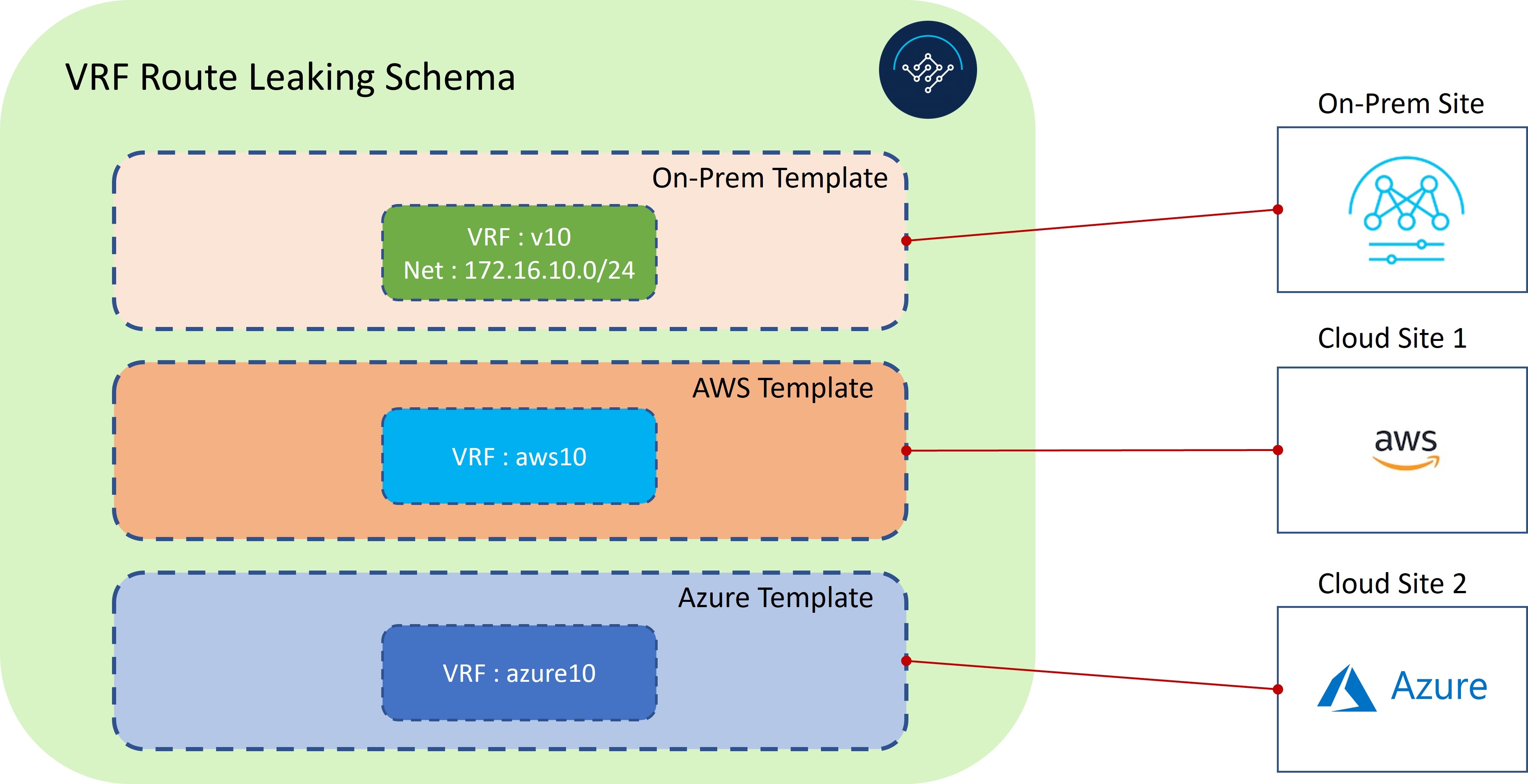
This route leaking use case uses separate templates for each site, which contains VRF and network definitions for the on-premises
site, whereas for cloud sites these templates only contain the VRF definition. Unlike the stretched VRF (intra-VRF) use case
described in Stretched VRF Use Case, which does not require any configurations for exchanging prefixes between the sites because the same VRF is stretched to
all sites, you must configure VRF leaking for this use case because each site uses a different VRF.
To propagate the prefixes between the sites (on-premises as well as cloud sites), you must explicitly configure route leaking
on the respective templates associated with the sites.
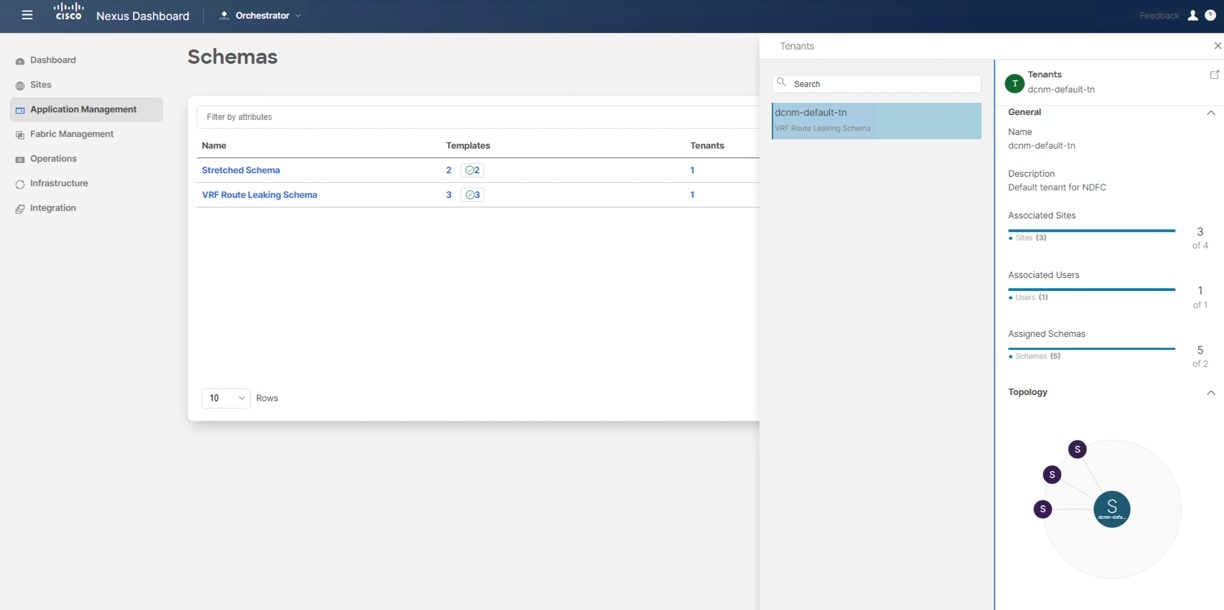
Figure 1.
As shown in the figure above, each site has a separate associated template, which contains VRF/network definitions specific
to that site only. On-Prem Template is associated to the NDFC managed on-premises site, whereas AWS Template and Azure Template are associated to the AWS and Azure cloud sites, respectively. Inter-VRF route leaking is configured explicitly between different
VRFs to allow communication between the sites.
Configure the Necessary Templates
Use the procedures in the following sections to configure the templates that you will need for the route leaking use case.
Configure the On-Premises Site Template
In this section, you will configure the On-Prem Template that will be associated to the NDFC managed on-premises site.
Procedure
Step 1
In NDO, navigate to Application Management > Schemas and click Add Schema.
Step 2
Provide the schema name and click Add.
For this use case, we will name the new schema VRF Route Leaking Schema.
Figure 2. You are returned to the Overview page for the new VRF Route Leaking Schema schema.
Step 3
Under the VRF Route Leaking Schema schema, click Add New Template.
Step 4
Choose the NDFC template.
Step 5
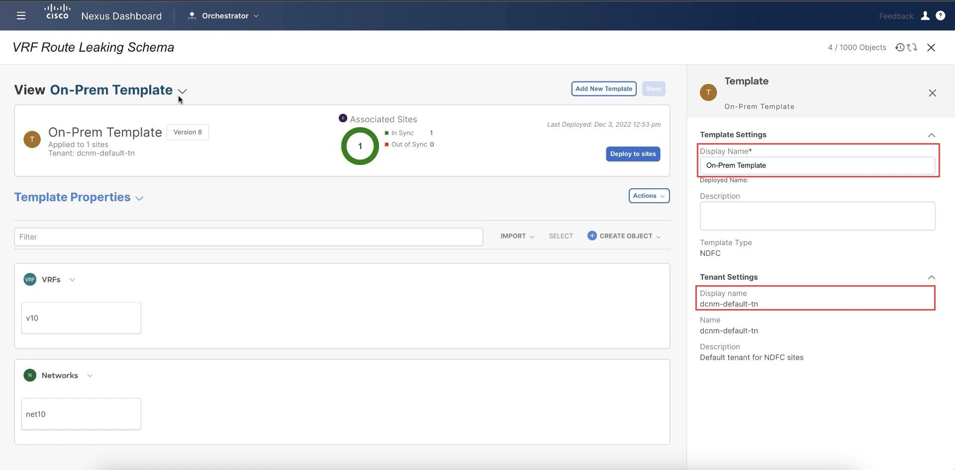
Enter a name in the Display Name field to create an NDFC-type template (for example, On-Prem Template).
Step 6
Select the dcnm-default-tn tenant in the Select a Tenant field to map the template to that tenant.
Figure 3.
Step 7
Under Template Properties, click Create Object and choose VRF to create a VRF that will be used with the NDFC managed on-premises site.
Note
If you have an on-premises VRF already created that you want to use instead of creating a new VRF, under Template Properties, click Import, then import the already-created VRF.
Currently, support is only available for importing VRFs and networks from on-premises sites.
Step 8
Enter a name in the Display Name field for this VRF (for example, v10).
Figure 4.
Step 9
Under Template Properties, click Create Object and choose Network to create a network.
Note
If you have a network already created that you want to use instead of creating a new network, under Template Properties, click Import, then import the already-created network.
Step 10
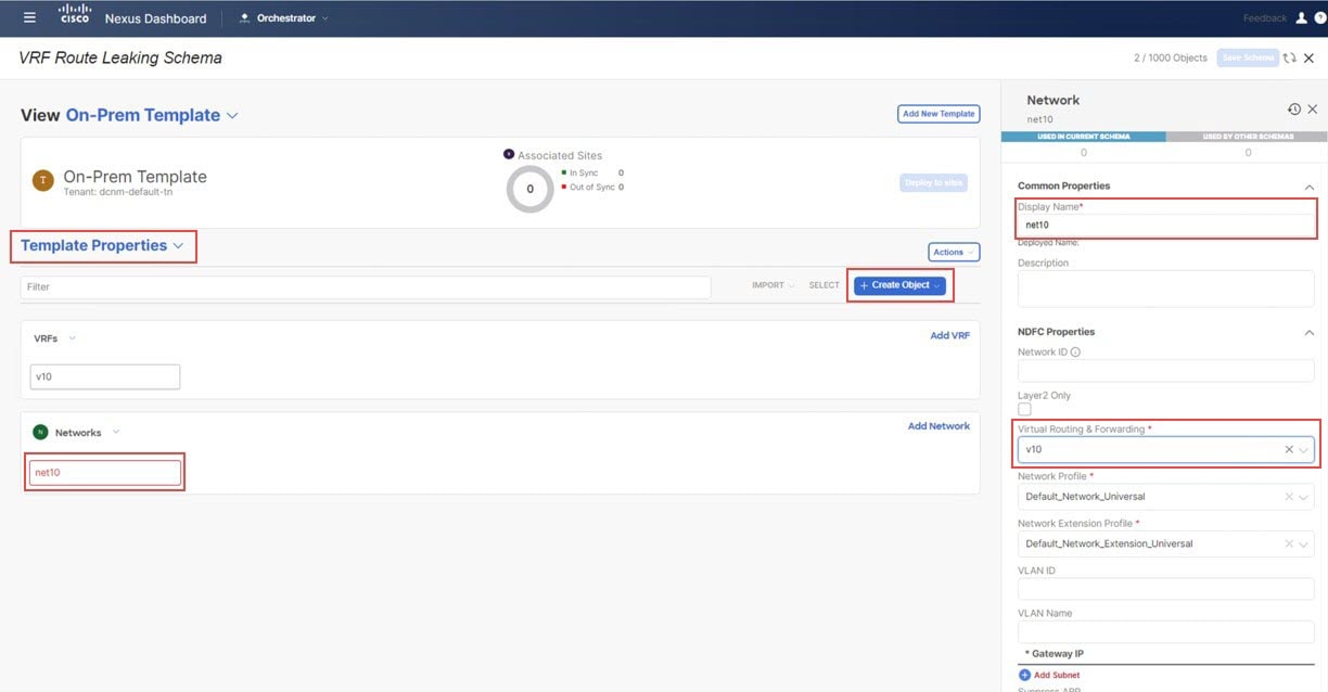
Enter a name in the Display Name field for the network (for example, net10).
Step 11
In the Virtual Routing & Forwarding field, choose the v10 VRF to map the net10 network to that VRF.
Figure 5.
Step 12
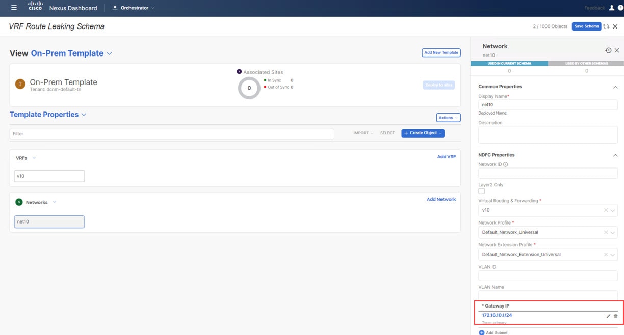
In the Gateway IP field, click Add Subnet and provide the gateway IP address, then click Add.
Figure 6.
The gateway IP address is now displayed in the Gateway IP field.
Figure 7.
Step 13
Define other optional parameters for this network, if necessary.
Step 14
In the Template Properties area, click Actions > Sites Association.
Figure 8.
Step 15
Associate this template only to the on-premises site (the Sydney site in this example use case), then click Ok.
Figure 9.
Step 16
Click Template Properties and select the on-premises site (the Sydney site in this example use case), then select the v10 VRF.
Step 17
In the right pane, click Add Static Leaf.
Figure 10.
The Add Static Leaf window appears.
Step 18
In the Leaf field, select the leaf/border/border gateway device where this VRF is to be deployed and click Ok.
In this example, you need to deploy the VRF on the leaf nodes (where the endpoints part of the network mapped to the VRF will
be connected) and on the BGW spine node to be able to extend the Layer 3 connectivity for the VRF towards the cloud sites.
Step 19
To attach the network to the leaf switches, click the net10 network, then click Add Static Port to add the ports where you want to deploy this network.
The Add Static Port window appears.
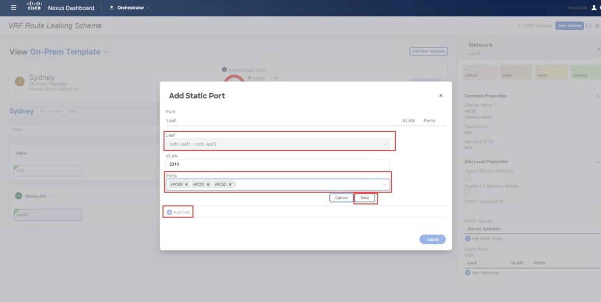
Step 20
In the Add Static Port window, click Add Path.
The Add Static Port window appears.
Step 21
In the Leaf field, select the device where you want to deploy this network.
Step 22
(Optional) Enter the necessary information in the VLAN field.
Step 23
In the Ports field, select the ports where you want to deploy this network.
Step 24
Click Save.
Figure 11.
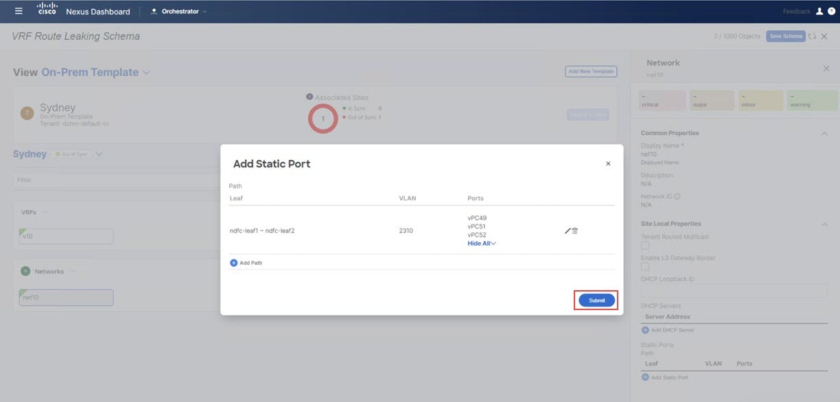
You are returned to the Add Static Port window.
Step 25
In the Add Static Port window, click Submit.
Figure 12.
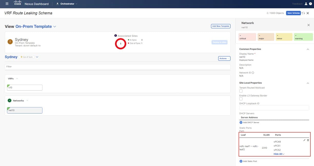
You are returned to the on-premises template window.
Figure 13.
Step 26
Click the arrow next to the on-premises site, and from the drop-down menu, select Template Properties.
Step 27
Click Deploy to Sites.
Figure 14.
Step 28
Deploy On-Prem Template to the sites.
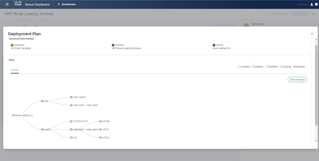
Click Deployment Plan for additional verification.
Click on the on-premises site to see the deployment plan for that specific site.
Figure 15.
Click Deploy to have NDO push the configurations to NDFC.
This pushes the NDO configurations to NDFC.
Step 29
In NDFC, verify that the VRF was deployed successfully.
Under the VRF Route Leaking Schema schema, click Add New Template.
Step 2
Choose the NDFC template.
Step 3
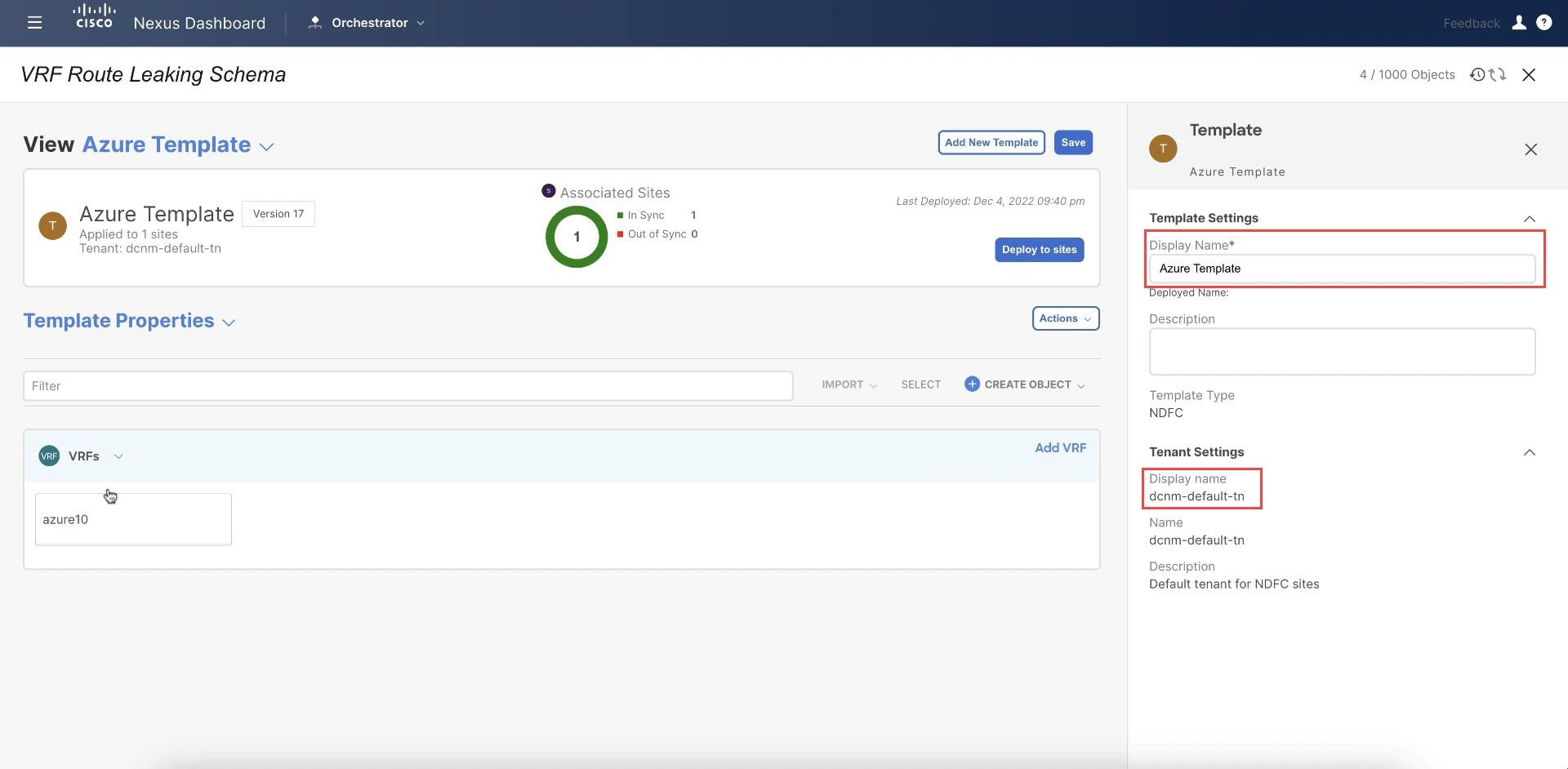
Enter a name in the Display Name field to create an NDFC-type template for the Azure site (for example, Azure Template).
Step 4
Select the dcnm-default-tn tenant in the Select a Tenant field to map the template to that tenant.
Figure 17.
Step 5
Under Template Properties, click Create Object and choose VRF to create a VRF that will be used with the Azure site.
Figure 18.
Step 6
Enter a name in the Display Name field for this VRF (for example, azure10).
Figure 19.
Step 7
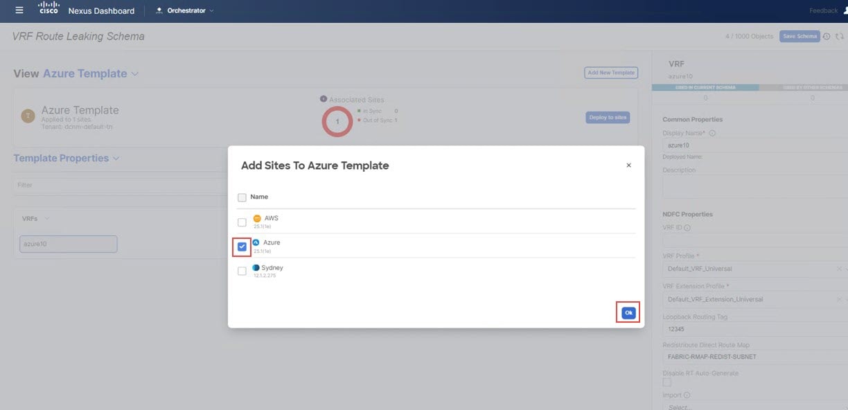
In the Template Properties area, click Actions > Sites Association.
Figure 20.
Step 8
Associate this template only to the Azure site, then click Ok.
Figure 21.
Step 9
Click the azure10 VRF, then click Add Region to create the VNet in a selected region.
The Add Cloud Region CIDRs window appears.
Step 10
In the Region field, choose the region where you want to create the VNet.
Step 11
In the CIDR field, click Add CIDRs and define a CIDR block for the VNet.
Step 12
Click Add Subnet to create the subnets, then click Save.
Figure 22.
Step 13
Check the box under the VNet Peering field, then select the hub network that was created on the Cisco Cloud Network Controller for Azure.
Figure 23.
Step 14
Click Ok.
You are returned to the Azure template window.
Step 15
Click the arrow next to the Azure site, and from the drop-down menu, select Template Properties.
Step 16
Click Deploy to Sites.
Step 17
Deploy Azure Template to the sites.
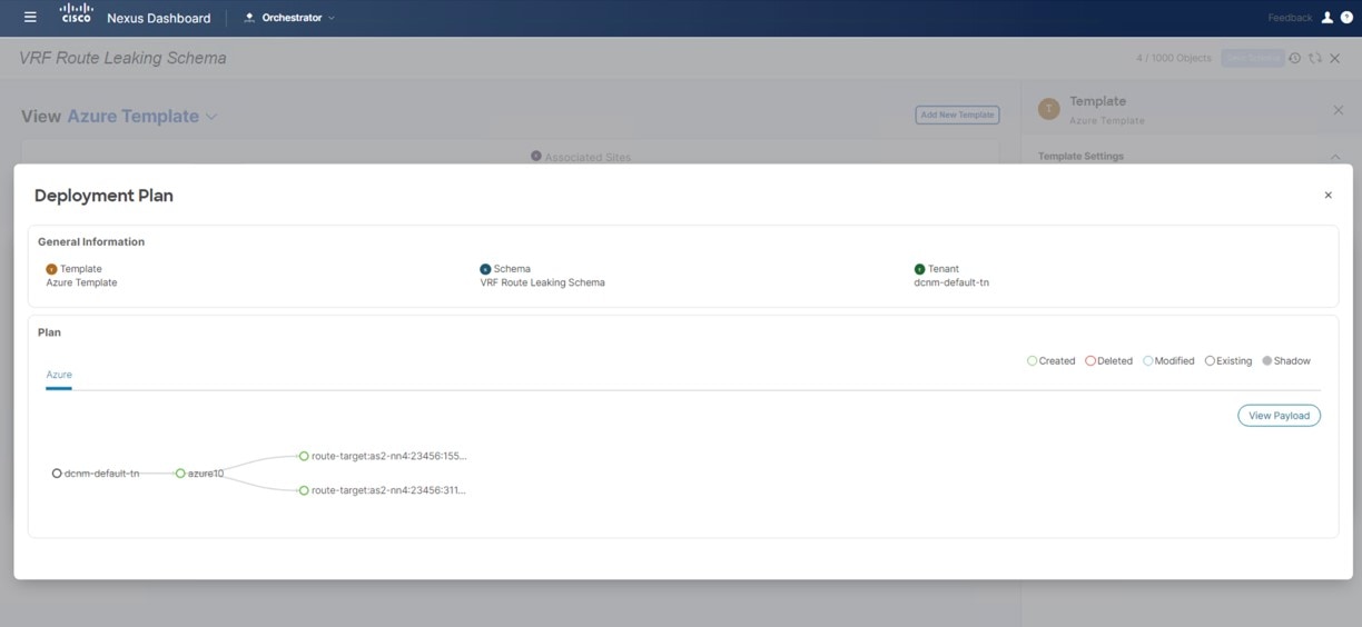
Click Deployment Plan for additional verification.
Click on the Azure site to see the deployment plan for that specific site.
Figure 24.
Click Deploy to have NDO push the configurations to NDFC.
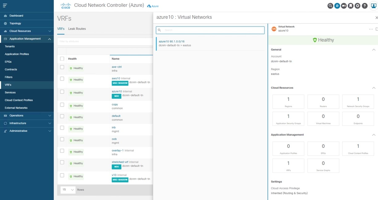
To verify that the configurations were pushed out correctly, connect to the Cloud Network Controller deployed on Azure and
navigate to Cloud Resources > Virtual Networks, then click the azure10 VNet and use the information in the Overview page for additional verifications:
Figure 25.
Note that there is no destination address configured at this point in the process, so the Azure site cannot talk to any other
site yet at this point in the process. This destination address configuration will be pushed out after you have completed
the route leaking procedure.
Under the VRF Route Leaking Schema schema, click Add New Template.
Step 2
Choose the NDFC template.
Step 3
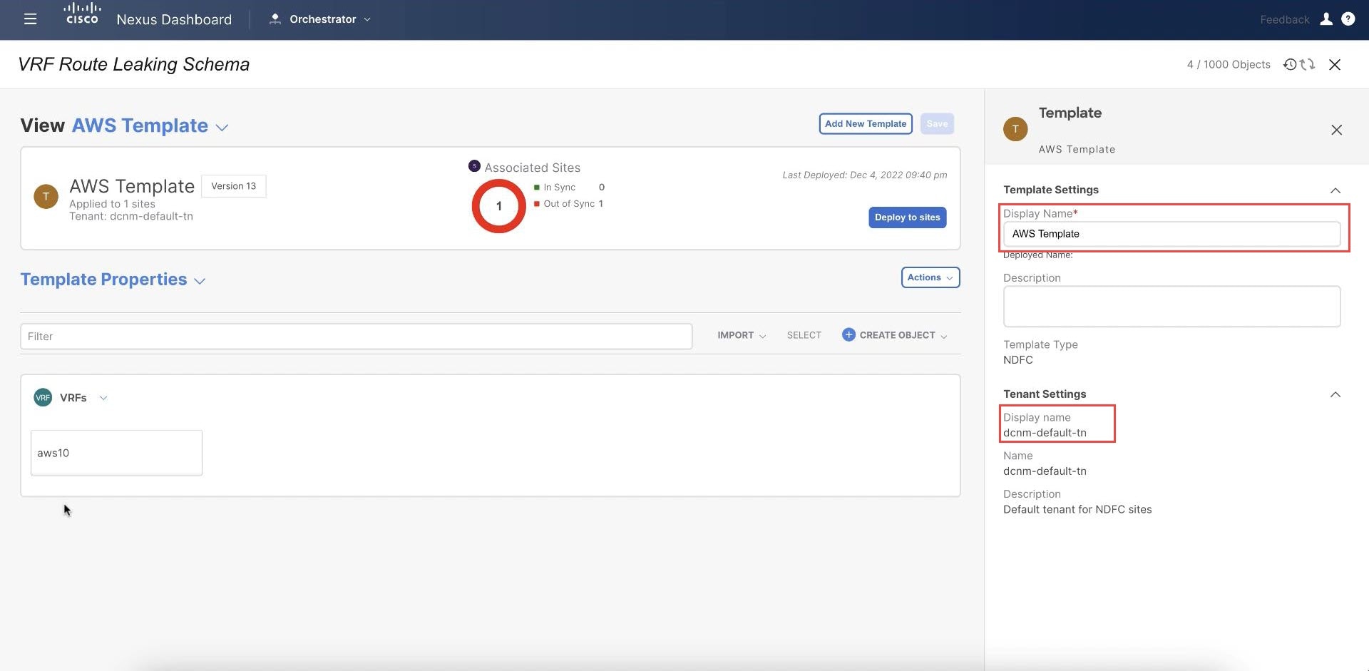
Enter a name in the Display Name field to create an NDFC-type template for the AWS site (for example, AWS Template).
Step 4
Select the dcnm-default-tn tenant in the Select a Tenant field to map the template to that tenant.
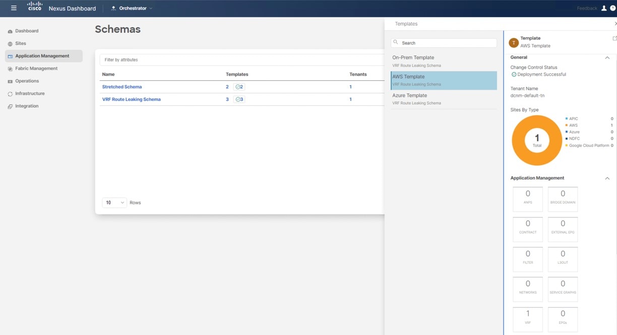
Figure 26.
Step 5
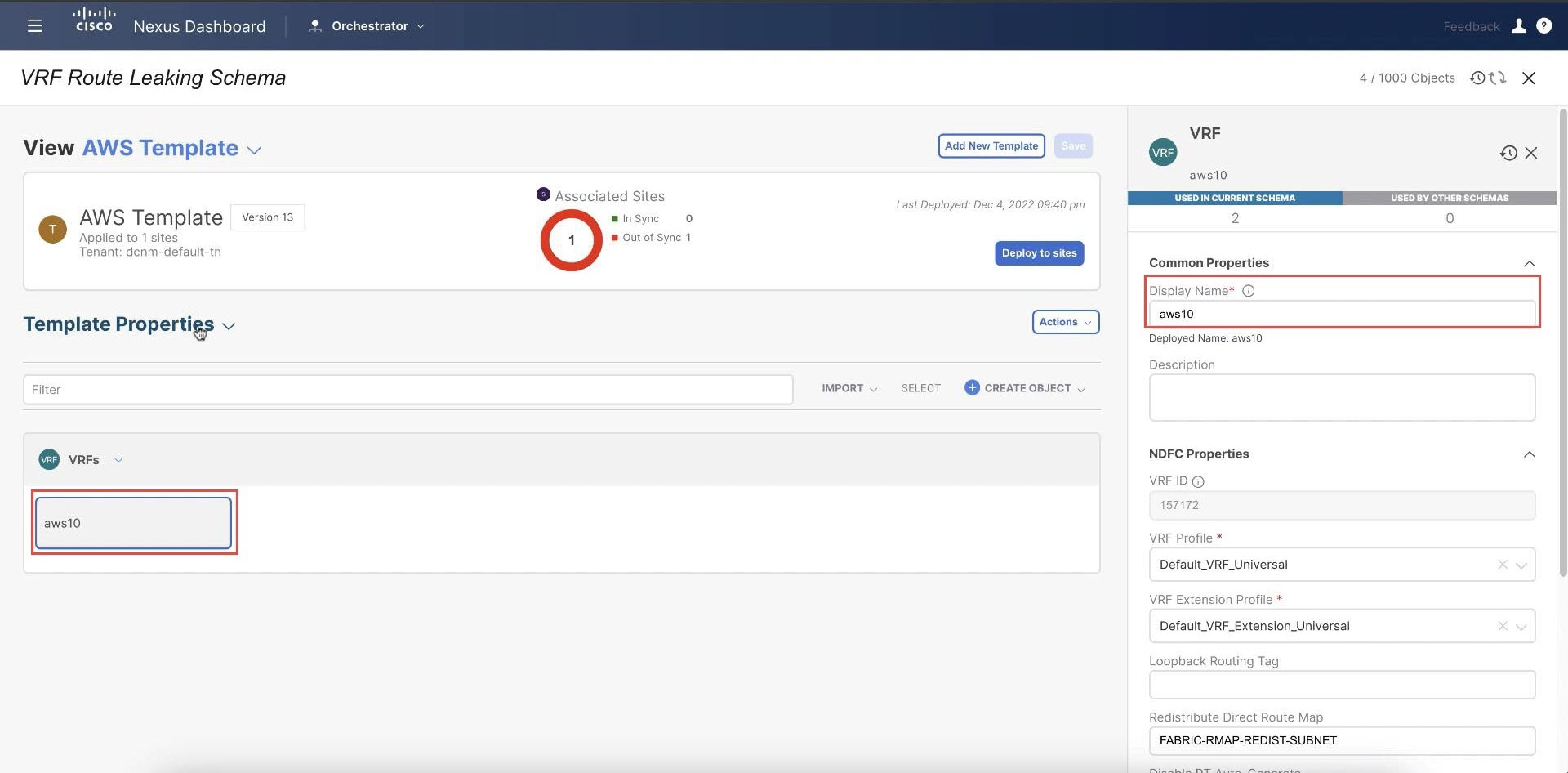
Under Template Properties, click Create Object and choose VRF to create a VRF that will be used with the AWS site.
Step 6
Enter a name in the Display Name field for this VRF (for example, aws10).
Figure 27.
Step 7
In the Template Properties area, click Actions > Sites Association.
Step 8
Associate this template only to the AWS site, then click Ok.
Figure 28.
Step 9
Click the arrow next to Template Properties, and from the drop-down menu, select the AWS cloud site.
Step 10
Click the aws10 VRF, then click Add Region to create the VPC in a selected region.
The Add Cloud Region CIDRs window appears.
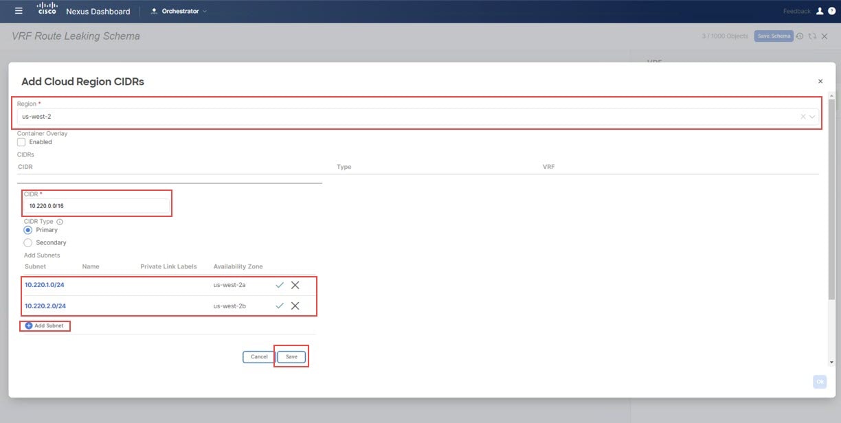
Step 11
In the Region field, choose the region where you want to create the VPC.
Step 12
In the CIDR field, click Add CIDRs and define a CIDR block for the VPC.
Step 13
Click Add Subnet to create the subnets and map them to the availability zones, then click Save.
Figure 29.
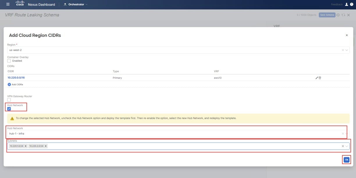
Step 14
Check the box under the Hub Network field, then select the hub network that was created on the Cisco Cloud Network Controller for AWS.
This allows the Cisco Cloud Network Controller to attach the subnets onto the transit gateway, which builds the connectivity
from those subnets to the transit gateway, where the transit gateway already has the connectivity to the Cisco Catalyst 8000Vs
in the cloud.
Step 15
In the Subnets field, map the subnets that will be used for the transit gateway.
It is best practice to have a dedicated subnet that will be used for the transit gateway.
Figure 30.
Step 16
Click Ok.
You are returned to the AWS template window.
Step 17
Click the arrow next to the AWS site, and from the drop-down menu, select Template Properties.
Step 18
Click Deploy to Sites.
Figure 31.
Step 19
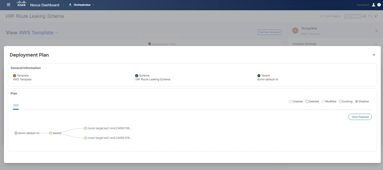
Deploy AWS Template to the sites.
Click Deployment Plan for additional verification.
Click on the AWS site to see the deployment plan for that specific site.
Figure 32.
Click Deploy to have NDO push the configurations to NDFC.
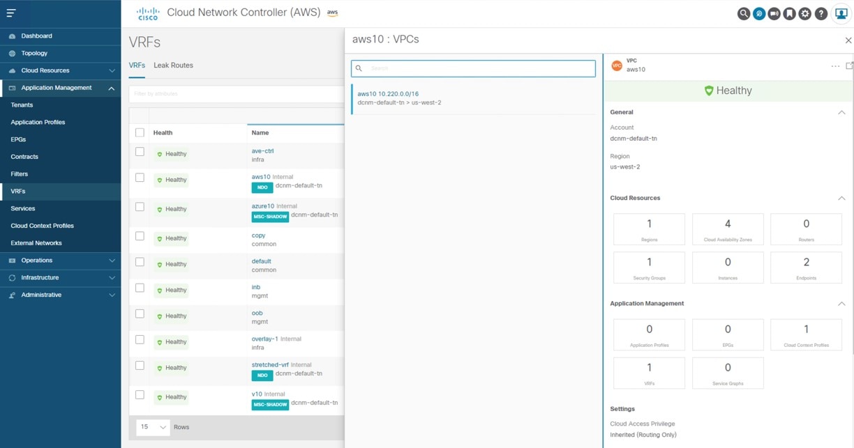
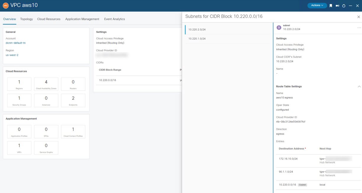
To verify that the configurations were pushed out correctly, connect to the Cloud Network Controller deployed on AWS and navigate
to Cloud Resources > VPCs, then click the aws10 VPC and use the information in the Overview page for additional verifications:
Figure 33.
Note that there is a destination address configured at this point in the process for AWS, but this shows only that this AWS
site can talk to itself; the AWS site cannot talk to any other site yet at this point in the process. The necessary destination
address configuration that will allow the AWS site to talk to another site will be pushed out after you have completed the
route leaking procedure.
Click the Azure Template that you configured earlier in these procedures and the dcnm-default-tn tenant.
Step 2
Click the azure10 VRF that you configured earlier in these procedures.
Step 3
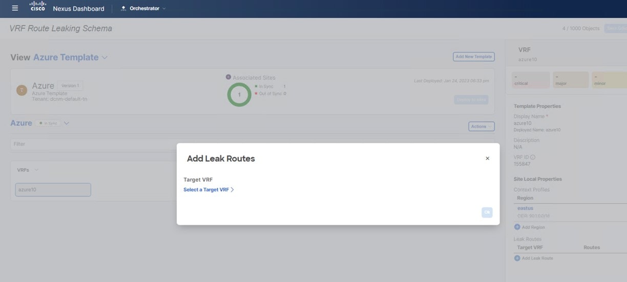
In the right pane, click Add Leak Route.
Figure 34.
The Add Leak Routes window appears.
Step 4
In the Add Leak Routes window, click Select a Target VRF.
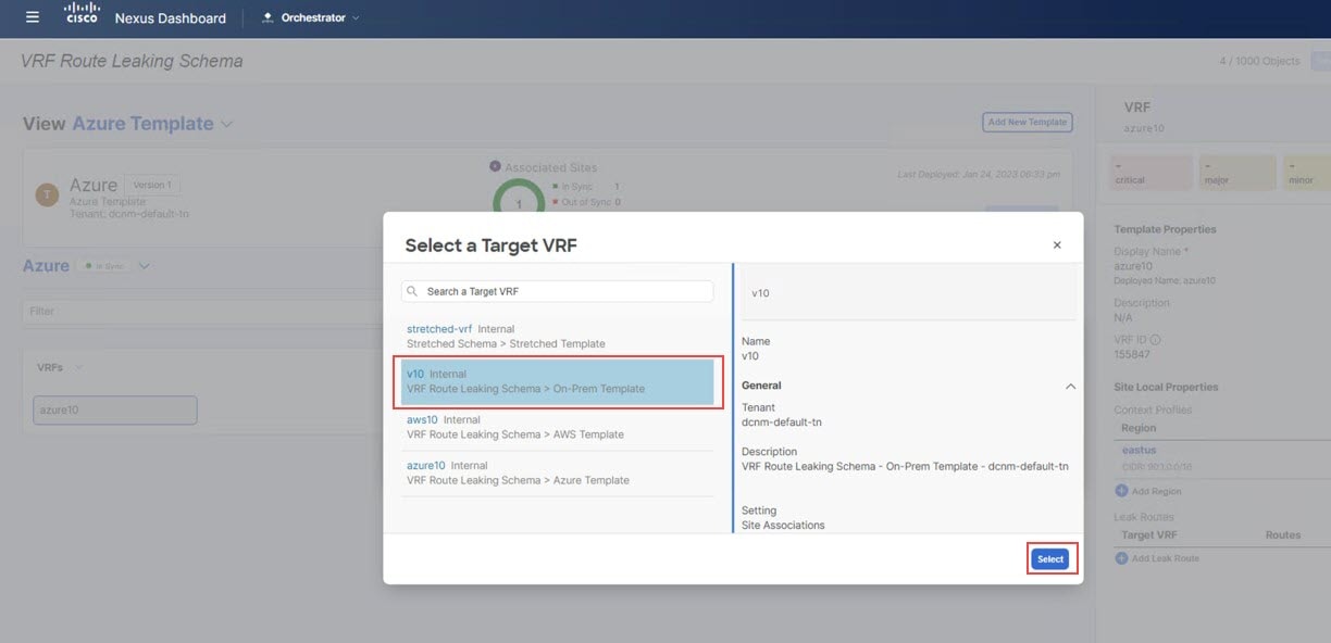
Figure 35.
The Select a Target VRF window appears.
Step 5
In the Select a Target VRF page, select the NDFC VRF (v10) that you want to leak routes to, then click Select.
Figure 36.
You are returned to the Add Leak Routes window.
Step 6
In the Add Leak Routes window, click Add Subnet IP, then add the Azure cloud subnets that you want to propagate to the on-premises site.
Note
The Add Subnet IP option allows leaking of only selective subnets. Alternatively, you can use the All Subnet IPs option instead in the case where all the prefixes need to be leaked into a destination VRF.
Figure 37.
For this use case, you will use the 90.1.1.0/24 subnet.
Step 7
Click Ok.
You are returned to the Azure Template page, where you can see the configuration for this route leak from the Azure VRF to the NDFC VRF.
In this section, you will configure the route leak from the Azure VRF (azure10) to the AWS VRF (aws10).
For these procedures, you will be going through the exact same procedures that you performed in Configure Route Leak from Azure VRF to NDFC VRF, except in these procedures, you will be selecting a different target VRF (the AWS target VRF in these procedures).
In the Select a Target VRF page, select the AWS VRF (aws10) that you want to leak routes to, then click Select.
Figure 38. You are returned to the Add Leak Routes window.
Step 2
In the Add Leak Routes window, add the subnets that you want to propagate to the AWS cloud.
For this use case, you will use the 90.1.1.0/24 subnet. Therefore, you will click the dropdown menu and choose the 90.1.1.0/24 subnet.
Figure 39.
Step 3
Click Ok.
You are returned to the Azure Template page, where you can see the configuration for this route leak from the Azure VRF to the AWS VRF, as well as the route leak
from the Azure VRF to the NDFC VRF that you configured in the previous set of steps.
Step 4
Click the arrow next to the Azure site, and from the drop-down menu, select Template Properties.
Step 5
Click Deploy to sites.
Figure 40.
The Deploy to sites window appears, showing where the template will be deployed.
Step 6
Click Deployment Plan for additional verification, then click on a site to see the deployment plan for that specific site.
Step 7
Click Deploy to have NDO push the configurations to the site specific controllers.
Click the AWS Template that you configured earlier in these procedures and the dcnm-default-tn tenant.
Step 2
Click the aws10 VRF that you configured earlier in these procedures.
Step 3
In the right pane, click Add Leak Route.
Figure 42.
The Add Leak Routes window appears.
Step 4
In the Add Leak Routes window, click Select a Target VRF.
The Select a Target VRF window appears.
Step 5
In the Select a Target VRF window, select the NDFC VRF (v10) that you want to leak routes to, then click Select.
You are returned to the Add Leak Routes window.
Step 6
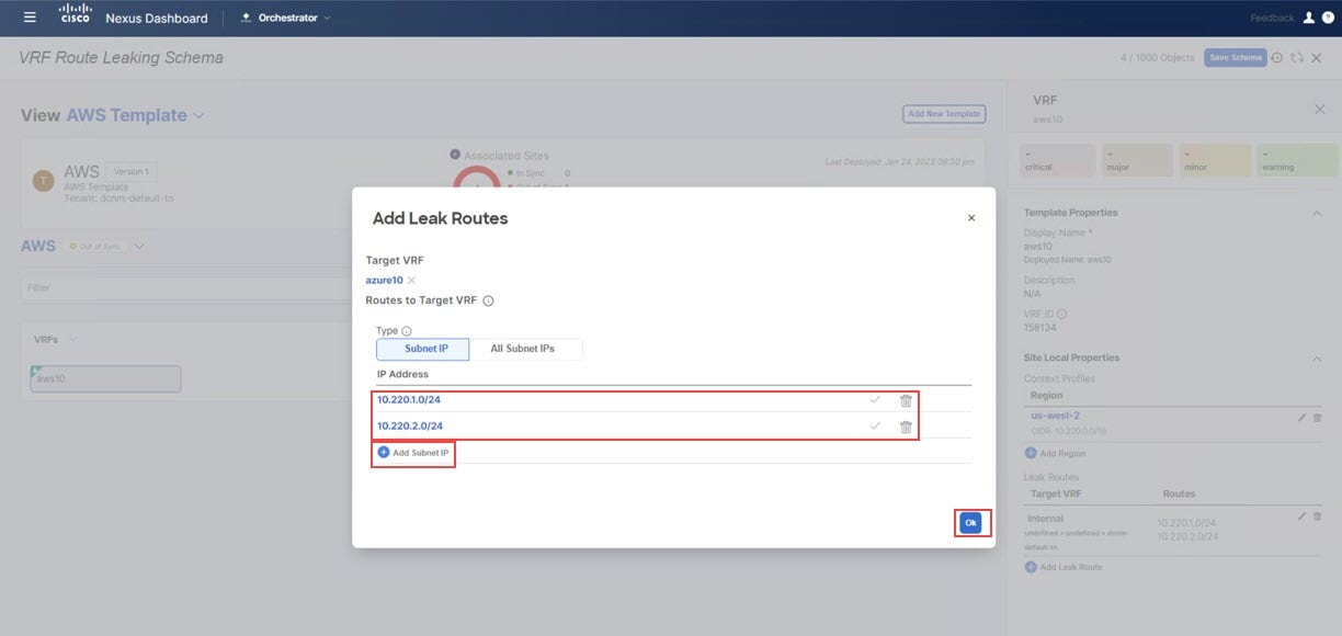
In the Add Leak Routes window, click Add Subnet IP, then add the AWS cloud subnets that you want to propagate to the on-premises site.
Note
The Add Subnet IP option allows leaking of only selective subnets. Alternatively, you can use the All Subnet IPs option instead in the case where all the prefixes need to be leaked into a destination VRF.
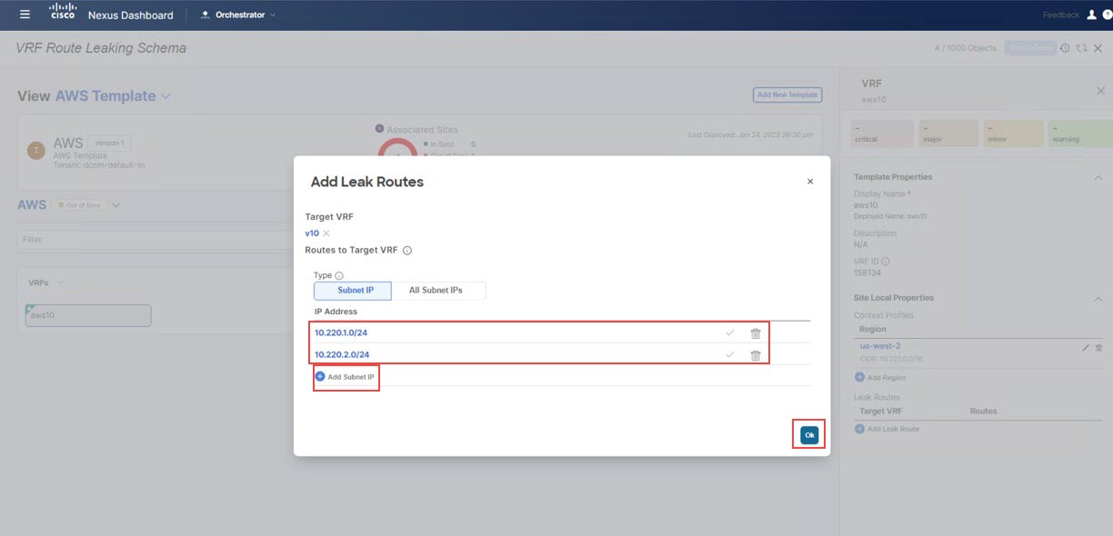
Figure 43.
For this use case, you will use the following subnets:
10.220.1.0/24
10.220.2.0/24
Step 7
Click Ok.
You are returned to the AWS Template page, where you can see the configuration for this route leak from the AWS VRF to the NDFC VRF.
In this section, you will configure the route leak from the AWS VRF (aws10) to the Azure VRF (azure10).
For these procedures, you will be going through the exact same procedures that you performed in Configure Route Leak from AWS VRF to NDFC VRF, except in these procedures, you will be selecting a different target VRF (the Azure target VRF in these procedures).
In the Select a Target VRF page, select the Azure VRF (azure10) that you want to leak routes to, then click Select.
You are returned to the Add Leak Routes window.
Step 2
In the Add Leak Routes window, add the subnets that you want to propagate to the Azure cloud.
For this use case, you will use the following subnets:
10.220.1.0/24
10.220.2.0/24
Therefore, you will click the dropdown menu and choose those subnets.
Figure 44.
Step 3
Click Ok.
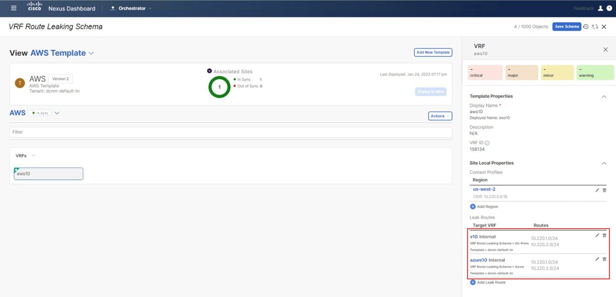
You are returned to the AWS Template page, where you can see the configuration for this route leak from the AWS VRF to the Azure VRF, as well as the route leak
from the AWS VRF to the NDFC VRF that you configured in the previous set of steps.
Figure 45.
Step 4
Click the arrow next to the AWS site, and from the drop-down menu, select Template Properties.
Step 5
Click Deploy to sites.
The Deploy to sites window appears, showing where the template will be deployed.
Step 6
Click Deployment Plan for additional verification, then click on a site to see the deployment plan for that specific site.
Step 7
Click Deploy to have NDO push the configurations to the site specific controllers (NDFC and Cloud Network Controller).
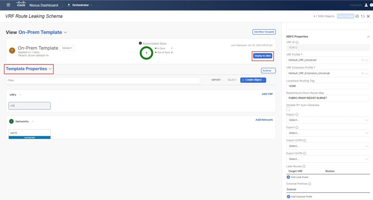
Click the On-Prem Template that you configured earlier in these procedures and the dcnm-default-tn tenant.
Step 2
Click the v10 VRF that you configured earlier in these procedures.
Step 3
In the right pane, click Add Leak Route.
Figure 46. The Add Leak Routes window appears.
Step 4
In the Add Leak Routes window, click Select a Target VRF.
The Select a Target VRF window appears.
Step 5
In the Select a Target VRF window, select the AWS cloud site VRF (aws10) that you want to leak routes to, then click Select.
You are returned to the Add Leak Routes window.
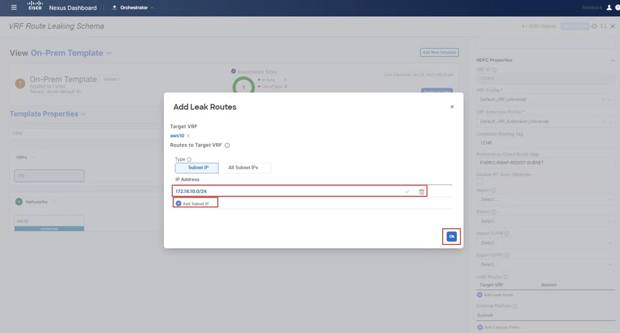
Step 6
In the Add Leak Routes window, click Add Subnet IP, then add the AWS cloud subnets that you want to propagate to the on-premises site.
Note
The Add Subnet IP option allows leaking of only selective subnets. Alternatively, you can use the All Subnet IPs option instead in the case where all the prefixes need to be leaked into a destination VRF.
For this use case, you will use the 172.16.10.0/24 subnet.
Figure 47.
Step 7
Click Ok.
You are returned to the On-Prem Template page, where you can see the configuration for this route leak from the NDFC VRF to the AWS VRF.
In this section, you will configure the route leak from the NDFC VRF (v10) to the Azure VRF (azure10).
For these procedures, you will be going through the exact same procedures that you performed in Configure Route Leak from NDFC VRF to AWS VRF, except in these procedures, you will be selecting a different target VRF (the Azure target VRF in these procedures).
In the Select a Target VRF window, select the Azure VRF (azure10) that you want to leak routes to, then click Select.
You are returned to the Add Leak Routes window.
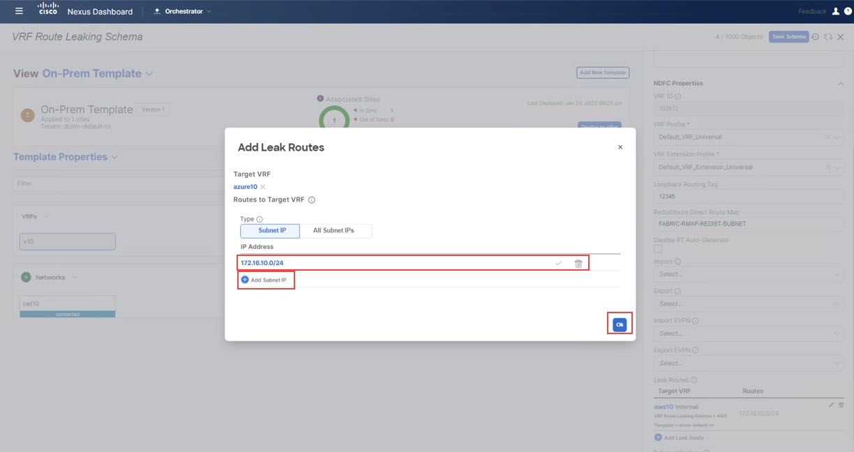
Step 2
In the Add Leak Routes window, add the subnets that you want to propagate to the Azure cloud.
For this use case, you will use the 172.16.10.0/24 subnet. Therefore, you will click the dropdown menu and choose the 172.16.10.0/24 subnet.
Figure 48.
Step 3
Click Ok.
You are returned to the On-Prem Template page, where you can see the configuration for this route leak from the NDFC VRF to the Azure VRF, as well as the route leak
from the NDFC VRF to the AWS VRF that you configured in the previous set of steps.
Step 4
Click the arrow next to the on-premises site, and from the drop-down menu, select Template Properties.
Step 5
Click Deploy to sites.
Figure 49.
The Deploy to sites window appears, showing where the template will be deployed.
Step 6
Click Deployment Plan for additional verification, then click on a site to see the deployment plan for that specific site.
Figure 50.
Step 7
Click Deploy to have NDO push the configurations to the site specific controllers (NDFC and Cloud Network Controller).
What to do next
Verify that the configurations were deployed successfully using the procedures provided in Verify the Configurations.
Verify the Configurations
In this section, you will verify that the configurations were deployed successfully. Note that for each of these verification
steps, the exact command that would be used specifically for the configurations in this use case are shown. Replace the appropriate
variables in each command based on your configuration.
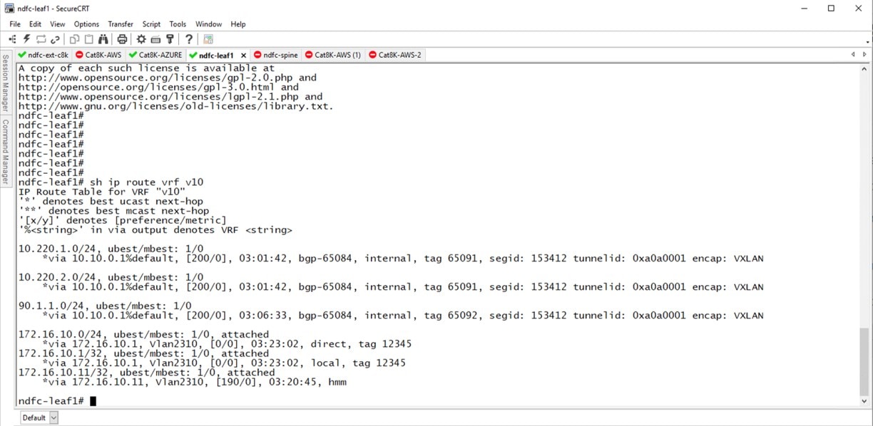
Enter sh ip route vrf v10 on the on-premises Border Gateway Spine device:
The routing table on the on-premises leaf switch shows that the reachable subnets are:
AWS: 10.220.0.0/16
Azure: 10.220.0.0/16
Step 3
Connect to the Cloud Network Controller deployed on AWS and navigate to Application Management > VRFs, and verify that you can see the Azure and NDFC VRFs.
Step 4
Remaining in the Cloud Network Controller deployed on AWS, perform a verification on the route table view.
Step 5
In the AWS console, perform a verification on the route table view.
Step 6
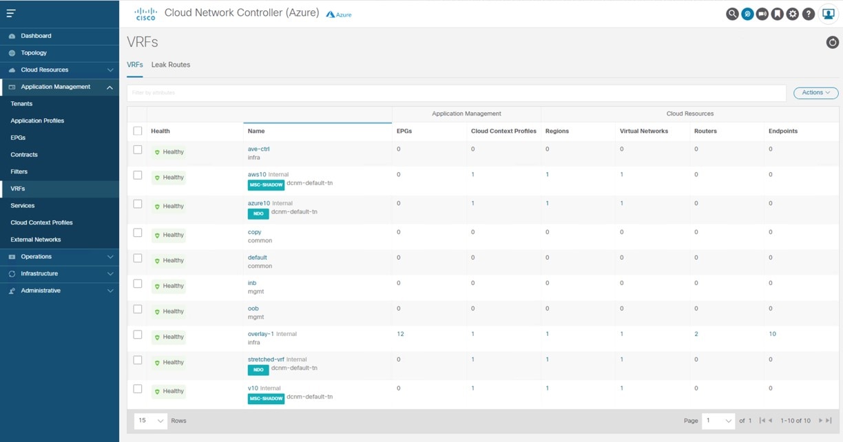
Connect to the Cloud Network Controller deployed on Azure and navigate to Application Management > VRFs, and confirm that you can see the AWS and NDFC VRFs:
Step 7
Remaining in the Cloud Network Controller deployed on Azure, navigate to Cloud Resources > Virtual Networks, then click the azure10 VNet and use the information in the Overview page for additional verifications.
Step 8
In the Azure console, perform additional verifications.


 Feedback