Cisco Nexus 3550 FDK User Guide
Bias-Free Language
The documentation set for this product strives to use bias-free language. For the purposes of this documentation set, bias-free is defined as language that does not imply discrimination based on age, disability, gender, racial identity, ethnic identity, sexual orientation, socioeconomic status, and intersectionality. Exceptions may be present in the documentation due to language that is hardcoded in the user interfaces of the product software, language used based on RFP documentation, or language that is used by a referenced third-party product. Learn more about how Cisco is using Inclusive Language.
- Updated:
- July 9, 2024
Chapter: ExaNIC FDK-Pro
- ExaNIC FDK-Pro
- Architecture Overview
- Installation and Compatibility
- Migrating from ExaNIC FDK v2
- Build system
- Adding a New Target
- Field Extract (field_extract.v)
- Frame Mux (frame_mux.v)
- Valid/ack Bus Mux (vabus_mux.v)
- Custom Framegen (custom_framegen.v)
- Asynchronous FIFO (async_fifo.v)
- Flag Synchronizer (flag_sync.v)
- Asymmetric Memories (ram_256_32.v and ram_256_64.v)
- Stream Pipeline (stream_pipeline.v)
- Streaming Bus Width Conversion (shim_32_to_64.v and shim_64_to_32.v)
- Trigger Example
- Steer Example
- Native loopback example
- Multi preload tx example
- Bridging example
- Soft-responder example
- Native Register Example
- Native Spam Example
- Ping example
- Native early sof example
- DDR4 example
- Native NIC example
- NIC 256b host if example
- Host spam example
- Steer 256b example
- Extra BARs example
- Native trigger example
- TCP trigger example
- ExaNIC FDK-Pro
- Architecture Overview
- Installation and Compatibility
- Migrating from ExaNIC FDK v2
- Build system
- Adding a New Target
- Interfaces
- Software Integration
- TCP Stack Integration
- Included Cores
- Example Designs
- Testbench and functional model
- Debugging with Vivado
- Remote JTAG Connection (XVC Server)
- Netlist variants
- Recovery image
- Supporting Platforms
ExaNIC FDK-Pro
Architecture Overview
The Cisco Nexus SmartNIC FPGA Development Kit (FDK) Pro enables the development of applications directly within the network card firmware using FPGA technology. This kit includes a range of examples that demonstrate potential applications:
- Native NIC Example: Connects the PCS modules of all ports to the host.
- Trigger Example: Pre-loads a reply that is sent when a specific pattern in incoming frames is detected.
- Ping Example: Supports direct frame sending, hardware timestamping, and custom frame communications.
- Steering Example: Enables custom flow steering based on destination IP, adaptable to higher-layer data.
- Bridging Example: Bridges two ports to redirect incoming traffic from one to the other.
- Soft Responder Example: Sends an immediate response upon the receipt of the first byte to measure MAC latency.
- Native Loopback Example: Handles packet forwarding, clock domain transitions, and buffering.
- Chipscope Example: Allows signal monitoring for debugging and performance assessment.
- Multi Preload TX Example: Pre-loads frames into FPGA memory for simultaneous transmission across multiple ports.
- Native Register Example: Demonstrates basic use of the PCI register interface.
- Native Spam Example: Creates a simple packet generator.
- Extra BARs Example: Utilizes additional register/memory spaces at BAR1 and BAR4.
- NIC 256b Host IF Example: Uses a 256-bit RX host interface to establish a NIC.
- Host Spam Example: Generates and sends packets from the FPGA to the host.
Installation and Compatibility
The FDK-Pro is designed for Linux environments and requires Xilinx Vivado version 2019.2 or later. It supports:
- Cisco Nexus SmartNIC models K3P-S, K3P-Q (XCKU3P FPGAs) with the free WebPACK edition of Vivado.
- Cisco Nexus SmartNIC+ V5P model with XCVU5P FPGA, which requires a full Vivado license.
The FDK-Pro is distributed as a tar file that organizes the project directory for ease of use. To download:
- Visit Cisco’s website.
- Go to Downloads.
- Search for and select the SmartNIC product.
- Download the FDK-Pro under Nexus SmartNIC.
Migrating from ExaNIC FDK v2
The FDK v2 minimizes the exposure of unsynthesized Cisco source code to end-users, incorporating more of it within the encrypted netlist. It provides restricted access, revealing solely the source code relevant to the target example designs, alongside RTL wrappers needed to connect user logic to the FDKs core functions or needed to connect to the included AMD/Xilinx IP cores, such as the GTY transceivers, PCIe core, etc
The FDK-Pro adopts a more open approach, providing increased access to the source code which gives visibility into various FDK components which empowers the users with faster development and debugging. In this new offering, the PCS (Physical Coding Sublayer) and FastMAC are still shared as an encrypted netlist.
Impact on Build Configuration and Scripting
- Build Scripts: FDK-Pro build scripts for comprehensive end-user configuration of the non-PCS related FDK components.
- File Locations: File/folder structure in the FDK-Pro version. This will be covered later in the document.
- Backward Compatibility: Though build scripts are not intended to be backward compatible with non-Pro build scripts, the RTL is intended to be.
Build Scripts
The compile_common.tcl script covers much of the scripting in the build process. The next section gives an overview of the script, its functionality, role within the flows, and how it integrates into the overall system.
compile_common.tcl
This is a shared script sourced during the building of packages in the FDK-Pro builds. It manages common build parameters across different builds. It extends variables common across the build scripts, like verilog_files or synth_args without overriding any value set previously by other scripts in the build process.
File Locations and Exposure
The FDK-Pro architecture has a new directory structure. The directory structure shared is shown below:
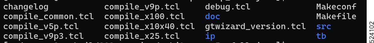
The list of files and directories inside /src is shown below: 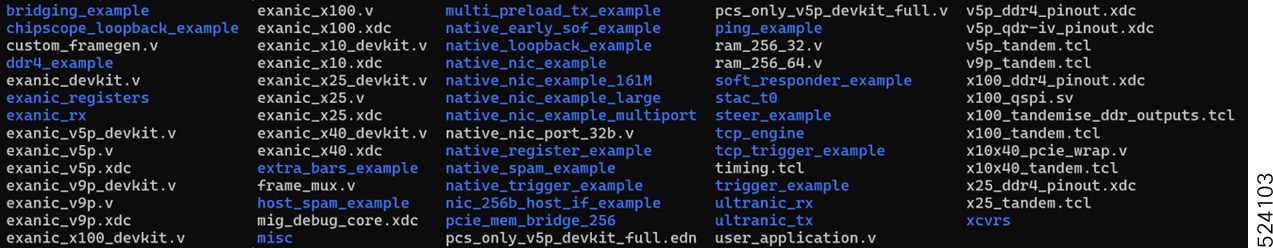
Additional Codes Exposed in FDK-Pro
Ultranic_rx
The ultranic-rx module processes the data stream from the MAC layer, segmenting it into 120B/128B chunks; for DMA pass-through, allowing for an early look at the first 120B of the frame, the other 8B are metadata used in the DMA control path. These chunks are given to the DMA engine and in parallel the traffic is directed to appropriate RX buffers. It supports DMA width of 256 bits with PCIe Gen3.
The components included for this packet processing are:
rx_chunk_assembler: This module receives data from the MAC layer and is responsible for assembling chunks of data of size 128B (15 QWORDs off the wire + 1 QWORD footer) in ultranic_rx in preparation for DMA transfers. It writes these assembled chunks into an intermediate RAM, which interfaces directly with the DMA engine. Additionally, this module selectively blocks packets not intended for our MAC address, unless promiscuous mode is enabled.
rx_buffer: This module acts as a dual-port memory, facilitating efficient data storage and retrieval of chunks of the data.
flow_steer: Module for matching inbound packets to rules. For each received frame, this module indicates whether it matches an IP or MAC flow steering rule programmed by software.ie BCAM steering the packets to different buffer rings based on the matches of a 5-tuple of the mac addresses, ip addresses and the IP protocol (UDP or TCP). It also keeps track of the current {gen_id, chunk_id} in each DMA ring, and provides a software interface for programming rules.
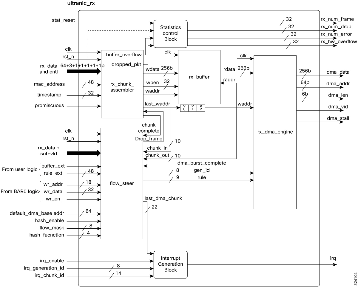
rx_dma_engine: DMA engine facilitates the efficient movement of data from the RX buffer to system memory by organizing the data into DMA data packets of 256 bit width and generating a DMA valid signal to indicate the presence of valid data.
Additionally, a few of the exanic_rx files, such as frame_info, are exposed in FDK Pro architecture, though the core functionality of the DMA is sourced from files in the ultranic_rx folder. All of the frame information for flow_steer module, including the header structure, types, and values, can be obtained from this frame_info module.
Ultranic_tx:
This module serves as the transmission pathway in UltraNIC, facilitating the transfer of data from the host to the Tx PCS layer. It provides a memory write interface for injecting frames and a transmit trigger queue to initiate transmissions. The module comprises the transmit buffer, command queue, transmit engine, and flag synchronization modules.
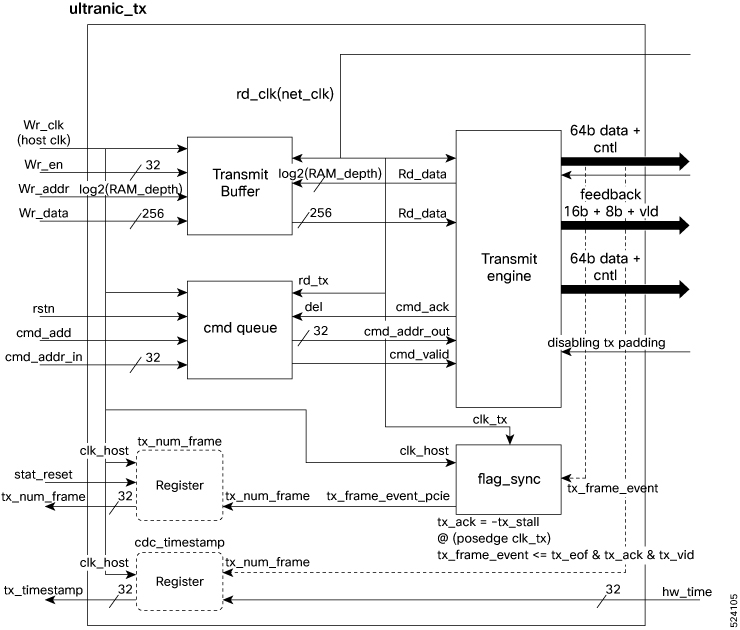
Transmit Buffer: The transmit buffer interfaces with the host via an address-aligned PCIe interface, with its data depth parameterized. Its storage capacity is determined by the TX_RAM_DEPTH, which sets the buffer size. Both ports feature an aperture of 256 bits.
Command Queue: This component takes the commands from the register interface and generates the control to the transmit engine. Internally it has gray coded circular FIFO for both clock domain crossing and command buffering. It utilizes one queue per 512 bytes, and the depth of the command queue depends upon the TX_RAM_DEPTH.
CMD_QUEUE_DEPTH = (TX_RAM_DEPTH * RAM_WIDTH_BYTES / 512)
Transmit Engine: Responsible for handling data from the transmit buffer, the transmit engine interprets commands specifying the chunk header address offset. It reads the header, accordingly, facilitating the completion of the send operation.
exanic_registers
Manages the register interface for the Ultrascale Series of ExaNICs.
pcie_mem_bridge_256
This module acts as a PCIE memory interface that connects the AXI stream interface with various local interfaces, For use with a Gen3x8 256b wide at 250Mhz interface, achieving a DMA bandwidth of approximately 64GBit/s.
tcp_engine (Accelerated TCP Engine - ATE)
The Accelerated TCP Engine (ATE) is a hybrid SW/HW TCP transmit engine that allows user logic to generate TCP frames from hardware and operates in "0" clock cycles. ATE implements a part of TCP in conjunction with exasock, the kernel bypass library for Cisco Nexus SmartNIC (formerly ExaNIC) cards. The software establishes a TCP connection and continues to provide the relevant connection state information to the firmware. Header generation, checksum calculation, as well as send and ack sequence numbers are thus handled internally by ATE without the involvement of custom user firmware or software.
ATE is designed to provide the lowest latency and smallest device footprint possible. The firmware only contains logic that is strictly necessary to send frames back-to-back at the lowest latency. Connection establishment, teardown, input handling, ACK handling, and windowing are all performed in software. As a result, ATE adds no additional latency over the standard TX MAC interface and requires roughly 1300 LUTs, 9 block rams and an Ultraram for a single port capable of 512 independent connections.
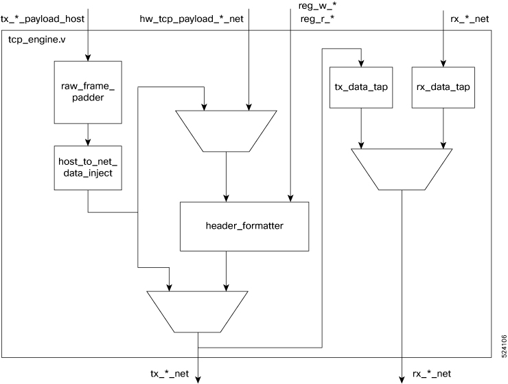
Following are the inputs to the tcp_engine:
- Transmit stream from host.
- The stream of TCP payloads from user firmware.
- Register reads and writes for setting up the connection parameters.
- Received Ethernet frames.
The critical path is from the hw_tcp_payload _* _net signals to the tx_*_net signals.
raw_frame_padder: This block receives input from ultranic_tx and adds required "0" padding to the input data when padding is disabled in the transmit engine.
host_to_net_data_inject: The host_to_net_data_inject block aligns the data cycle with the Start of Frame (SOF), which is output by the DMA engine a cycle after SOF. This block also handles host to net clock conversion and converts data from 64-bit to 32-bit width.
header_formatter:
The header formatter is responsible for serializing out the MAC, IP and TCP headers. Header fields come from three sources: Hardcoded constants, Calculated fields and Fields stored in ultraram. Per connection register space:
| Offset | Name |
|---|---|
| 0 | Dest_mac |
| 1 | Dest_mac, Source_mac |
| 2 | Source_mac |
| 3 | ethertype, beginning of ip |
| 4 | length, identification |
| 5 | flags, frag, ttl, protocol |
| 6 | checksum, source_ip |
| 7 | Source_ip, dest_ip |
| 8 | dest_ip, source_port |
| 9 | dest_port, seq_num |
| 10 | seq_num, ack_num |
| 11 | ack_num, flags |
| 12 | window_size, tcp_checksum |
| 13 | urgent pointer, payload |
The calculated fields are the IP length, TCP length, IP header checksum and TCP checksum. User firmware supplies the payload length. The IP and TCP lengths are calculated by adding different constants to this number. The IP header checksum is a function of only the fields in the IP header. The TCP checksum requires a partial checksum of the payload so this needs to be supplied by the user firmware a few cycles in.
The non-constant, non-calculated, parts of the headers are stored in ultraram. Once the header serialization is finished, it switches the output mux over to user firmware so that it can provide the payload. It also starts acking the user firmware, so it knows to progress the stream. In parallel, it adds the current packet size to the sequence number stored in ultraram so that it has the correct value ready for the next packet.
tx_data_tap: This block receives tx_data_net as input and does the width conversion from 32 bit to 64 bit and the clock domain crossing from clock net to clock host.
rx_data_tap: This block receives rx_data_net and does the same width conversion and clock conversion like tx_data_tap.
Build Definitions/Parameters
Variants
In the FDK-Pro, there are two significant variants: VARIANT and PCS_VARIANT.
- VARIANT: This is the configuration identifier that includes all settings relevant to the entire FDK build, encompassing both PCS (Physical Coding Sublayer) and non-PCS related configurations.
- PCS_VARIANT: This variant is a subset of the VARIANT, containing only those elements that are pertinent to PCS logic. It is derived directly from the VARIANT by omitting any substrings that do not affect the PCS logic.
- Example: If VARIANT is full_fastmac_txbuf64, then PCS_VARIANT will be full_fastmac because the txbuf64 component is irrelevant to the PCS logic and pertains only to host-side logic.
In FDK-Pro, in the compile_common script, the pcs_variant is dynamically generated by filtering out non-PCS related substrings from the VARIANT.
Synthesis Arguments (synth_args)
The synthesis arguments are the arguments applied during the synthesis of general, non-PCS components.
License Installation
Cisco provides a specific license file required by Xilinx Vivado to synthesize the FDK Pro development kit.
For local installation, place the license file in your ~/.Xilinx/ directory and ensure the ~/.flexlmrc file includes XILINXD_LICENSE_FILE=/home/username/.Xilinx to set the license search path correctly.
For installation on a license server, modify the license file by replacing Xilinx_SERVER with the server's name and SERVER_PORT with the port number, typically 2100. Start the FlexLM License Server with the command:
lmgrd -c Xilinx.lic:exablaze_fdk.lic
If Vivado fails to find the license, it will generate a synthesis error indicating a missing license for the netlist cell 'exanic_v5p_devkit', instantiated as 'exanic_x10_devkit_inst'. Refer to the Xilinx documentation and the FAQ for more details on the Vivado licensing system.
Determining Your Host ID
When generating a license, Cisco will request your "host ID". The host ID is the MAC address of any physical network interface on your license server (for network/floating licenses) or the host running Vivado (for node-locked licenses). The MAC address can be determined using the ifconfig or ip addr commands, e.g.:
$ ifconfig ... enp8s0: flags=4163 mtu 1500 inet 10.0.0.100 netmask 255.255.255.0 broadcast 10.0.0.255 inet6 fe80::ae22:bff:fe78:184c prefixlen 64 scopeid 0x20 ether **ac:22:0b:78:18:4c** txqueuelen 1000 (Ethernet) ... $ ip addr ... 2: enp8s0: mtu 1500 qdisc fq_codel state UP group default qlen 1000 link/ether **ac:22:0b:78:18:4c** brd ff:ff:ff:ff:ff:ff ...
Build system
The development kit includes a build system comprising a Makefile and a Vivado TCL script (compile.tcl) for various fully functional example applications. To initiate, source the Vivado environment using:
$ source /opt/Xilinx/Vivado/2019.2/settings64.sh
The Makefile requires specifying PLATFORM, TARGET, and optionally VARIANT. Run make without arguments to view available options for these parameters. PLATFORM designates the target card (e.g., x25, x100 or v5p). TARGET specifies the application to build, such as:
- native_nic_example
- trigger_example
- ping_example
- steer_example
- bridging_example
- soft_responder_example
- native_loopback_example
- native_spam_example
- extra_bars_example
- nic_256b_host_if_example
- host_spam_example
- multi_preload_tx_example
- native_register_example
- native_early_sof_example
- ddr4_example
- steer_256b_example
The source code for each application is contained in its own directory under the src/ directory. Users can create their own targets just by creating a new directory under src/.
VARIANT specifies the 'variant' of the netlist to use. Each netlist may be compiled with different options, for example full_multirate is a netlist that contains multirate (1/10G) support at the expense of an extra cycle of latency. If VARIANT is not provided, the default netlist will be used.
To build a native_loopback_example for the SmartNIC+ V5P, using the full_fastmac variant:
$ make PLATFORM=v5p TARGET=native_loopback_example VARIANT=full_fastmac
In the FDK-Pro, when constructing a design with the full_fastmac_txbuf64 variant, it suffices to specify the VARIANT as full_fastmac. This adjustment is necessary as the txbuf64 component does not affect the PCS logic but is solely relevant to host-side operations.
Moreover, within the FDK-Pro, one would rather specify the tx_buf size in the Makeconf file. The non-pcs variants (variants related to host) are configured in the Makeconf file inside the package before build. The variants that can be configured through Makeconf are hw_time64, txbufN, rxbufN, rxhostwidth256, ip_rulesN, mac_rulesN, no_dma, enable_ate.
In addition to the target, platform and variant, there are also several optional build flags:
- NOREBOOT=1: Prevents FPGA reload when the PCIe reset line is asserted. Useful for loading a bitstream via JTAG followed by a system reboot.
- NOTANDEM=1: Disables Xilinx tandem (two-stage) boot mode, which can help if systems fail to detect the SmartNIC, though Cisco does not recommend using this setting by default.
- JTAG=1: Adds support for JTAG debugging with an ILA core over PCIe using exanic-xvcserver and disables all other JTAG access to the FPGA. Further details are in the Debugging with Vivado section.
- AUTORXEQ=-1|1: Overrides the default AUTO RX Equalization settings of the PCIe core, with -1 disabling and 1 enabling. This setting can impact PCIe link reliability on some servers.
- PCIE250=1: Sets the PCIe core's internal clock frequency to 250MHz, compared to the default 500MHz. Although it aids in achieving timing closure, it increases the host to FPGA round trip latency by approximately 96ns.
- TCP_ENABLES=0: Bitmask to enable ports for the Accelerated TCP Engine (ATE).
These parameters are configurable in the Makeconf file, which includes explanations for each. Adjustments to these settings should be considered based on specific hardware behaviors and troubleshooting needs.
The build system outputs several files, including a SmartNIC firmware image (.fw) in the outputs/ directory. This firmware can be updated on a SmartNIC using the exanic-fwupdate utility. After updating and rebooting, executing exanic-config will display the system configuration and status like the following:
`$ exanic-config exanic1
Device exanic1:
Hardware type: ExaNIC V5P
Serial number: 643F5F01956C
Temperature: 34.2 C VCCint: 0.85 V VCCaux: 1.81 V
Fan speed: 5835 RPM
Function: customer application
Firmware date: 20240502 (Thu May 2 06:55:54 2024)
Customer version: 1714632954 (663338fa)
External 12V power: detected`
The hot reload feature allows for FPGA reload/reconfiguration without rebooting the host system.
The firmware date indicates when Cisco built the FDK, while the customer version shows when the image was built by the customer. Use the date command to convert these timestamps into a readable format if needed. $ date -d @1714632954 Thu May 2 16:55:54 AEST 2024
Adding a New Target
To create a new target application in the development kit, customers can start by duplicating and modifying an example design or developing a new one from scratch. This involves creating a new directory under src/, e.g., src/my_app, and including the necessary files.
Required Files
- src/my_app/my_app.v or my_app.vhd is the top level of your design
Optional Files
- src/my_app/config.tcl: Recommended for setting FDK configuration options.
- src/my_app/constraints.xdc: Specifies any Vivado constraints for your application.
- Additional source files (src/my_app/ *.v, *.vhd, and *.sv) are included automatically.
The following is an example of a config.tcl file that demonstrates use of the available configuration options:
set app_ports {regif memif net_rx net_tx host_rx host_tx user_led} set app_physical_ports {0 1} set net_data_width 32 set clocking_model native set debug_clk clk_tx
Configuration Option Reference
The configuration files are essential for defining how the application interacts with Cisco IP and system hardware. The following are the configuration options currently available:
app_ports
- Default: {regif memif net_rx net_tx host_rx host_tx}
- Valid values: regif, memif, net_rx, net_rx_early_sof, net_tx, net_tx_err, net_tx_eof_no_crc, net_tx_abort_frame, net_tx_ifg_compress, host_rx, host_tx, host_tx_size, port_enabled, port_speed, rate, link_up, hw_time, disable_tx_padding, led_user, pps_in, bar1, bar4, net_tx_tcp, ddr, dna, application_id, force_promisc
- Example: set app_ports {regif memif net_rx net_tx host_rx host_tx}
- Description: defines the ports available in the top-level module interface of the application.
app_physical_ports
- Default: {0}
- Example: set app_physical_ports {4 5}
- Description: determines which NIC physical ports the application uses, with unused ports defaulting to standard host interfaces.
net_data_width
- Default: 32
- Valid params: 32 or 64
- Example: set net_data_width 32
- Description: sets the data width of network data buses, offering 32 bits for lower latency or 64 bits for backward compatibility and ease of use.
clocking_model
- Default: native
- Valid values: host, dual, native
- Example: set clock_model native
- Description:
| Value | Description |
|---|---|
| host | All buses are synchronous. to clk_host |
| dual | The dual clocking model synchronizes network interface buses to a single network clock (clk_net) for all port transactions and uses a separate host clock (clk_host) for host-side interfaces. This mode exists for compatibility with old FDKs and should not be used for new projects. Currently only supported with net_data_width = 64. |
| native | Network receives data synchronized to clk_rx_net[*], with a unique clock for each RX port. Network transmit data uses clk_tx_net, shared across all TX ports, while other interfaces use clk_host. This model requires a net_data_width of 32. |
Avoid using the "dual" clocking mode in new projects due to its focus on compatibility with older FDK versions. Choose between "host" or "native" modes based on your latency and usability needs. Host mode is suitable if your workflow involves frequent host interactions, providing latency similar to native mode but with easier clock domain management. It adds one clock cycle of latency when using a net_data_width of 32 due to a stream pipeline in the TX path. Native mode is optimal for high-performance requirements where the host is not part of the critical data path, but it requires manual management of all clock domain crossings.
debug_clk
- Default: none
- Valid values: the name of any clock in the design
- Example: set debug_clk clk_tx
- Description: when set to anything other than 'none', connects all ports marked with (*mark_debug="true" *) to an ILA core operating in the specified clock domain. Be aware that using more than half of the ILA core's available port width will trigger a warning.
Interfaces
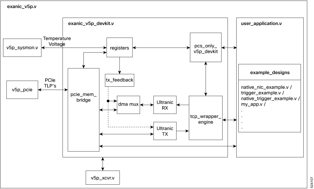
The SmartNIC development kit provides extensive access to transmit and receive datapaths, and a user-accessible register and memory space. The top-level file, such as exanic_v5p_devkit.v for v5p, serves as a wrapper that integrates the SmartNIC IP core netlist with custom user applications. This setup ensures essential connections between the netlist and the user's application for seamless integration. The example designs included in the kit, which come with pre-established connections, offer a solid foundation for users to enhance and adapt for additional functionalities. Similar structures are used across different platforms, with variations in filenames.
Clocking, Reset, and Misc
The user interface for the SmartNIC development kit includes key clocking and reset signals:
- clk_host (1 bit): A 250 MHz clock sourced from the PCIe bus, with all "_host" suffix signals synchronized to this clock.
- Depending on the chosen clocking model, either clk_net (1 bit) or separate clk_tx_net (1 bit) and clk_rx_net (1 bit per port) is used.
- rst_n (1 bit): An enable signal asserted once clk_host is stable and synchronized to this clock.
The SmartNIC development kit includes several optional ports, which are available based on the app_ports settings:
- hw_time_net (32 bit): A counter with 3.1 ns resolution, shared with the timestamp counter for received packets, and synchronized to clk_tx_net. This counter can be adjusted by the host if a PTP client is active or via the exanic-clock-sync utility, affecting the counting frequency through periodic cycle adjustments.
- hw_time_host (32 bit): This is hw_time_net transitioned into the host clock domain (clk_host).
- port_enabled (1 bit per port): Shows whether the host OS has activated the interface, synchronized to clk_host.
- port_speed (2 bits per port): Indicates the port speed set by the host OS, where the values are 0=Reserved, 1=100M, 2=1G, 3=10G. Note that speeds 100M/1G are fully supported only on SmartNIC K3P-S (X25); on other models, they're supported only on the first lane. This port is synchronous to clk_host.
- link_up (1 bit per port): Signals that the MAC has established a network link, synchronized to clk_rx_net. Link establishment may take several seconds.
- pps_in (1 bit): A direct connection from the PPS input pin to the user application.
Register Interface
The user register interface supports up to 2048 readable and/or writable 32-bit registers, where all read and write operations use full 32-bit words without byte-specific enables. All signals are synchronized to clk_host. The interface utilizes the following signals:
- reg_w_en (1 bit): Asserted simultaneously with reg_w_addr and reg_w_data to indicate a register write request.
- reg_w_data (32 bit): Write data from the host.
- reg_w_addr (11 bit): Address for the register write, incrementing per 32-bit word, not by byte offset.
- reg_r_addr (11 bit): Address for register reads, incrementing similarly to write addresses.
- reg_r_en (1 bit): Read enable signal asserted with reg_r_addr to validate the address.
- reg_r_data (32 bit): Data for the register specified by reg_r_addr, provided when reg_r_ack is asserted.
- reg_r_ack (1 bit): Must be asserted when reg_r_data is valid in response to a read. User logic has 16 cycles to assert reg_r_ack following reg_r_en before a timeout occurs, after which the PCIe logic will issue an unsupported request response.
Memory Interface
The user memory interface in the SmartNIC development kit is designed for write-only operations from the host, suitable for storing transmit buffers without support for host read-back. It operates synchronized to clk_host with key signals including:
- mem_w_en (32 bit): Controls which bytes are written based on the offset from mem_w_addr.
- mem_w_addr (19 bit): Specifies the DWORD offset for write operations within BAR2 of the development kit.
- mem_w_data (256 bit): Accommodates up to 32 bytes of data per write, dictated by the write enables.
This interface maintains address alignment, ensuring mem_w_addr[2:0] remains zero and byte enables dictate write locations. Memory mapping features non-cached and write-combining attributes, causing potential reordering and combining of writes in the CPU’s buffer. Memory state synchronization with the FPGA can be achieved by flushing the write buffer through a register write, guaranteeing memory state accuracy as seen by the firmware.
Extra BARs Interface
Users can enable additional BARs beyond the standard allocations if their application requires more memory spaces. BAR1 is configured similarly to the register space, and BAR4 mirrors the behavior of the memory space. These extra BARs are reserved exclusively for user applications and can be resized or reconfigured as needed by editing the .xci files located in the ip/ directory of the FDK archive. For guidance on utilizing these additional BARs, refer to the provided software and firmware examples described under "extra BARs example." The behavior of signals in these additional spaces mirrors those in the standard register and memory interfaces. They are listed below for convenience.
- bar1_w_d (32 bit)
- bar1_w_a1 (32 bit)
- bar1_w_en1 (1 bit)
- bar1_r_a (32 bit)
- bar1_r_en (1 bit)
- bar1_r_d (32 bit)
- bar1_r_ack (1 bit)
- bar4_w_d (256 bit)
- bar4_w_a (32 bit)
- bar4_w_en (32 bit)
Network Interface
The user application interfaces with the Cisco low-latency MAC to send and receive packets on the network. However, certain interface signals like rx_early_sof_net, tx_eof_no_crc_net, and tx_abort_frame_net are only available with the 10G PCS/MAC, not the 100M & 1G versions. Key signals for received data include:
- rx_data_net (32 or 64 bits per port): Delivers packet data directly from the network. The first byte appears at byte 0.
- rx_sof_net (1 bit per port): Indicates the reception of the first data word.
- rx_early_sof_net (1 bit per port): Signals incoming preamble, indicating an impending rx_sof_net assertion (available only in 32-bit native mode for 10G).
- rx_eof_net (1 bit per port): Asserted on the last cycle of a received frame, showing the final bytes including the CRC.
- rx_len_net (2 or 3 bits per port): Shows how many bytes in the final data signal are valid at EOF.
- rx_vld_net (1 bit per port): Indicates valid receive data. Note: validity may vary within frames due to 64b/66b encoding in 10G Ethernet.
- rx_err_net (1 bit per port): Indicates abnormal frame termination, such as early sender abort or link loss, with no subsequent rx_eof_net.
- rx_crc_fail_net (1 bit per port): Asserted post-EOF if CRC check fails, with timing dependent on build options.
- rx_timestamp_net (32 bit per port): Timestamp counter for the first byte of the received frame, offering 3.1 ns resolution.
Signals are synchronized to clk_rx_net in native mode, clk_net in dual mode, and clk_host in host mode. Signal width scales with port numbers, and bit slicing is used for signal selection per port. The application must process packets at line rate, as there is no mechanism to apply back pressure.
The SmartNIC development kit provides a transmit interface that allows the user application to both monitor and manipulate outgoing Ethernet frames, as well as transmit its own frames. All Ethernet frames from the user must start with the destination MAC address's first byte and end at the payload's last byte. The SmartNIC handles CRC calculations and appending automatically. The FPGA application has the following signals which connect through to the Ethernet transmission logic:
- tx_data_net (32 or 64 bits per port): Data for transmission, starting with the first byte of the destination MAC address at bits 7 to 0.
- tx_sof_net (1 bit per port): Asserted with the first data word to signify the start of frame.
- tx_eof_net (1 bit per port): Asserted with the last data word to signify the end of frame.
- tx_len_net (2 or 3 bits per port): Indicates the number of valid data bytes in the final cycle at EOF.
- tx_vld_net (1 bit per port): Indicates valid data on the transmit data bus; this signal is deprecated and should not be relied on in native mode.
- tx_ack_net (1 bit per port): Acknowledges data acceptance from the application; effective during active packet transmission.
- tx_err_net (1 bit per port): Corrupts the CRC for the current frame but does not end the frame.
- tx_eof_no_crc_net (1 bit per port): Ends the frame transmission without appending a CRC; available only in 32-bit native mode for 10G operations.
- tx_abort_frame_net (1 bit per port): Aborts the current frame without sending an EOF; also specific to 32-bit native mode for 10G operations.
- tx_ifg_compress_net (1 bit per port): Compresses the interframe gap to the minimum allowed, used cautiously based on downstream device capabilities.
These signals are synchronized to clk_tx_net in native mode, clk_net in dual mode, and clk_host in host mode. It is important to note that there is no mechanism to stall packet transmission once started, and the tx_ack_net may drop unexpectedly. For the 100M and 1G PCS/MAC, unsupported signals when asserted do not cause harm but have no effect, except tx_eof_no_crc_net which acts like tx_eof_net.
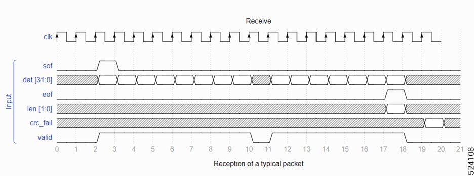
Timing diagrams
The provided timing diagrams clarify edge cases and ambiguities related to packet reception in the SmartNIC development kit.
The diagram illustrates a typical packet reception starting with the sof signal activating and ending with eof. Notably, the vld signal may deactivate at any point, as demonstrated when it drops mid-packet rendering the data invalid during that cycle. Additionally, the len signal is only relevant when eof is asserted. The timing of the crc_fail signal's validity varies based on whether the FDK is configured with the "Extra CRC Reg" option by Cisco; in the demonstrated scenario with this option enabled, crc_fail activates two cycles post-eof.
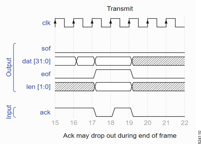
The timing diagrams provided illustrate packet transmission dynamics, showing how a typical packet is transmitted, akin to the reception process but with the valid signal replaced by ack. At the start of transmission, both sof and the first data word must remain constant until the ack signal is confirmed high on a rising edge. Note that ack may drop unexpectedly during packet transmission, requiring all signals to maintain their current values in the subsequent cycle. Additionally, ack can be high even when a packet is not being actively transmitted, as shown in the first cycle of the waveform. In this instance, ack being high indicates that the MAC is prepared to initiate packet transmission immediately. However, this readiness does not guarantee readiness in subsequent cycles unless the user firmware asserts sof on the current cycle, triggering the start of packet transmission.
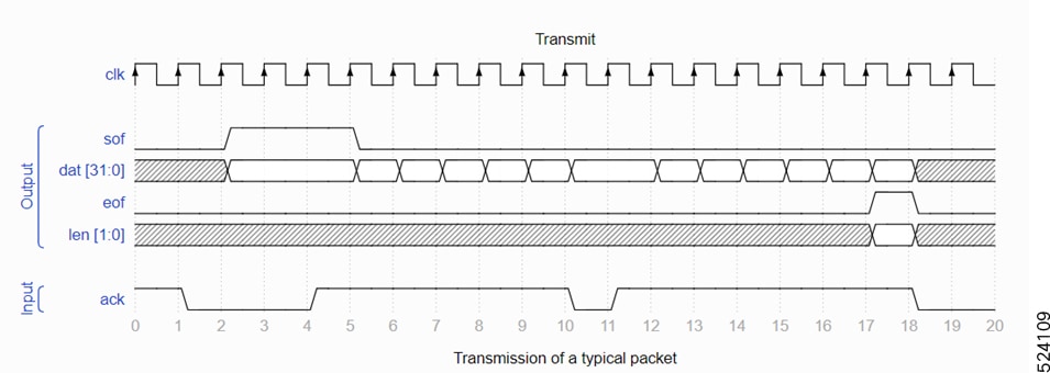
The diagrams depict common pitfalls and corner cases in packet transmission, specifically highlighting a scenario where the ack signal is deasserted at the end of a frame. In such cases, all related signals, including eof, len, and ack, must remain constant while ack is deasserted to ensure proper handling and stability in the transmission process.
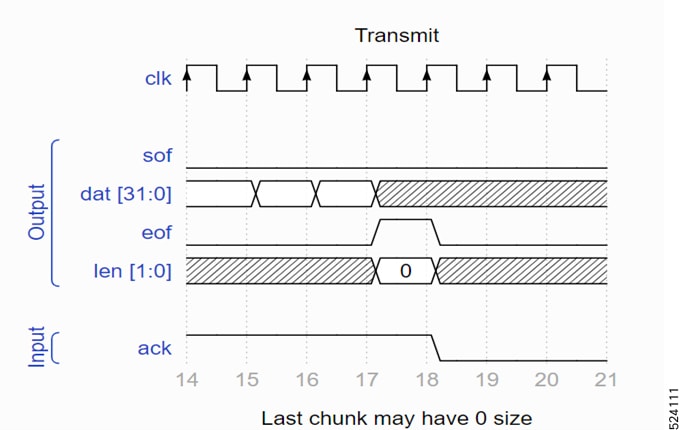
The diagram shows packet transmission where the last chunk size is zero. When eof is asserted with no valid bytes on the last cycle, it indicates that the packet actually ended in the previous cycle, and no valid data bytes are necessary in the current cycle.
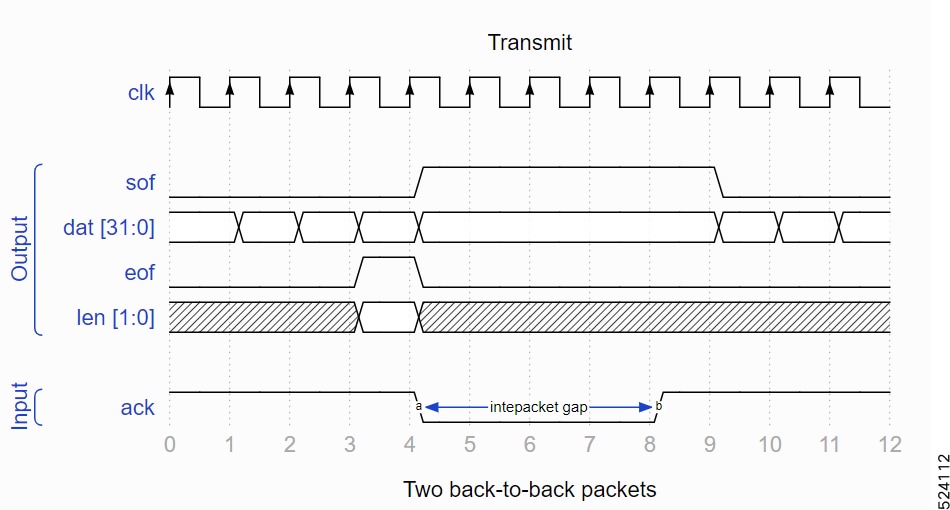
The diagram illustrates the transmission of back-to-back packets, showing that once the end of a frame is acknowledged, the ack signal is deasserted and remains so for several cycles. This de-assertion by the MAC prevents the user from violating Ethernet’s interpacket gap requirements.
Differences from AXI
The MAC interface in our development kit, while similar to the familiar AXI stream used by many FPGA engineers, incorporates specific differences for the sake of efficiency.
RX Side:
- rx_sof_net: An additional signal that is redundant as packet start can be identified by the first high signal from rx_vld_net after an end of frame.
- rx_len_net: Encoded as a binary number rather than a bitmask (like tkeep in AXI) because arbitrary invalid bytes within a chunk are not possible. This encoding aligns with the DMA engine interface.
TX Side:
- tx_len_net: Also encoded as a binary number.
- No valid signal to MAC: Avoiding a valid signal prevents incorrect implications that a user can halt data mid-packet. Instead, tx_sof_net indicates the first valid data chunk, requiring continuous validity of data until the end of the frame.
Host Interface
The host-side interface of the SmartNIC development kit facilitates bidirectional packet forwarding between the host software and the network. This interface mirrors network-side semantics, allowing straightforward connections between host and network data paths, such as connecting rx_*_net to rx_*_host for incoming packets and tx_*_host to tx_*_net for outgoing packets. This setup can function as a basic network interface or be enhanced with more complex interactions.
Host Receive Signals:
- rx_data_host (64 or 256 bits per port): Carries incoming packet data to be sent via PCI Express.
- rx_sof_host, rx_eof_host (1 bit per port each): Signal the start and end of a frame.
- rx_len_host (3 or 5 bits per port): Indicates the number of valid bytes in the final data signal at EOF.
- rx_vld_host (1 bit per port): Validates the accompanying signals.
- rx_err_host, rx_crc_fail_host (1 bit per port each): Signal frame errors and CRC failures.
- rx_timestamp_host (32 bit per port): Provides a hardware timestamp for the packet.
- rx_match_host (8 bit per port) and rx_buffer_host (6 bit per port): Allow tagging and steering of frames to different user buffers.
Host Transmit Signals:
- tx_data_host (64 bits per port): Contains outgoing packet data from the host.
- tx_sof_host, tx_eof_host, tx_len_host (1 bit per port for SOF and EOF, 3 bits for LEN): Manage the packet's beginning, end, and length.
- tx_vld_host, tx_ack_host (1 bit per port each): Validate data and control packet flow.
Additional Features:
- rx_afull_host (1 bit per port): Indicates nearing full capacity of the internal buffer, advising against new data transfers.
- Padding Control: The DMA engine automatically pads frames that are below the minimum size unless disabled per port.
These signals are vital for managing data flow and ensuring accurate packet handling between the host and the network, providing a robust platform for advanced networking applications within the SmartNIC framework.
DDR Interface
The DDR interface provides read and write access to DRAM installed on the card. Note that not all SmartNICs have DRAM installed:
- SmartNIC+ V5P: ships as standard with 9GB of DDR4 DRAM
- SmartNIC K3P-S (X25): can optionally be supplied with 4GB of DDR4 DRAM
- SmartNIC K3P-Q (X100): can optionally be supplied with 9GB of DDR4 DRAM
The DDR interface on the SmartNIC includes three categories of signals: reading, writing, and shared signals between both operations. Here is a concise overview:
Shared Signals:
- c0_ddr4_ui_clk: A 161MHz clock essential for all DDR interactions.
- c0_ddr4_ui_clk_sync_rst: An active-high reset signal for DDR-related user application logic.
- ddr_npres: Active low signal indicating the physical presence of DRAM.
- ddr_reset: Active high output that resets all DDR logic and the DRAM itself.
- c0_init_calib_complete: Active high signal indicating completion of DDR module calibration.
- c0_ddr4_app_rdy: Active high signal showing readiness of the DDR interface to accept commands.
- c0_ddr4_app_en: Strobe signal for addressing and command inputs.
- c0_ddr4_app_addr: 30-bit address output for DDR requests.
- c0_ddr4_app_cmd: 3-bit command output, with '000' for write and '001' for read commands.
Read-Specific Signals:
- c0_ddr4_app_rd_data_valid: Active high input indicating data validity.
- c0_ddr4_app_rd_data: 256-bit input providing data from read commands.
- c0_ddr4_app_rd_data_end: Indicates the last cycle of output data for a read command.
Write-Specific Signals:
- c0_ddr4_app_wdf_rdy: Active high input showing readiness to receive write data.
- c0_ddr4_app_wdf_wren: Strobe for write data.
- c0_ddr4_app_wdf_data: 256-bit output providing data for write commands.
- c0_ddr4_app_wdf_mask: 32-bit output for byte-keep masking, preventing byte updates.
- c0_ddr4_app_wdf_end: Indicates the last cycle of output data for a write command.
These signals facilitate robust DDR memory operations, allowing for efficient data writing and reading processes in the SmartNIC's architecture.
Software Integration
Low Level
The user application in the SmartNIC development kit interacts with host software by accessing register and memory spaces, and by modifying or tagging packets before they are transferred to the host. This is facilitated by libexanic functions:
- exanic_get_devkit_registers(): Retrieves a pointer to 32-bit unsigned values in the register space.
- exanic_get_devkit_memory(): Retrieves a pointer to byte values in the memory space.
These address spaces are customizable according to the specifics of the user's FPGA application. An example from the trigger_example.v in the FDK shows how register reads are handled:
`/* Register reads. */
always @ (posedge clk_host) begin
reg_r_ack <=reg_r_en;
case (reg_r_addr)
`h0: reg_r_data <= FIRMWARE_ID;
`h1: reg_r_data <= VERSION;
`h2: reg_r_data <= armed;
`h3: reg_r_data <= match_length;
. . .`
Reading from register 0 outputs the value 0xEB000001, demonstrated by the command:
$ ./exanic-devkit-register-read exanic0 0 0x000: 0xEB000001 (-352321535)
Additionally, the application can send dummy Ethernet frames with custom ethertypes to the host for advanced data communication. These frames are DMA transferred and processed by the host using libexanic, including any user-defined data. This setup allows for robust and flexible interaction between the FPGA and host system software.
TCP Stack Integration
The SmartNIC driver package features exasock extensions, enhancing applications with the ability to access the next set of TCP headers for specific sockets. In conjunction with the development kit, these functions empower the host to handle TCP state management through kernel sockets bypassed transparently by exasock, enabling the SmartNIC to deliver rapid responses to predefined user events.
An example exasock-tcp-responder-example.c, demonstrates using these capabilities with the trigger example firmware. This example illustrates how standard UNIX socket calls can establish a TCP connection to a server, and how the SmartNIC can send a TCP reply following the reception of a UDP packet.
Included Cores
The SmartNIC FPGA development kit ships with source code for IP cores that are useful for performing common tasks.
Field Extract (field_extract.v)
The field extract core can be used to extract an arbitrary length field from received frames. To use the core, instantiate it by specifying the parameters BYTES(The byte width of the field to extract) and OFFSET(The offset in bytes of the field in the frame, measured from the start of the frame). Examples of using this core are shown in the ping and flow steering example applications.
Frame Mux (frame_mux.v)
The frame mux core provides a way to share a single frame output interface (for example, rx_host or tx_usr) between two sources of frames. It provides buffering so that interfaces that cannot be 'stalled', such as the receive interface, can be arbitrated without loss of data. The frame mux also allows two ports to be 'bridged' together, much like the SmartNIC bridging functionality. As an example, the frame mux can be used to connect port 0 receive to port 1 transmit, whilst also allowing the host to transmit via port 1. In this mode of operation, the frame mux has an optional FCS removal mode.
The frame mux core has the following parameters:
- DEPTH: The total buffering depth of the two FIFOs contained within the frame mux. This is the maximum number of QWORDs that the frame mux can store.
- IN0_DELAY, IN1_DELAY: The amount of 'prebuffering' to apply to a particular input of the mux, prior to providing it to the output.
- STRIP_FCS0, STRIP_FCS1: selects whether to remove the last 4 bytes from a particular input.
Valid/ack Bus Mux (vabus_mux.v)
The valid/ack bus mux core provides the same functionality as the frame mux core but without any buffering or registering delays. This is useful where latency is important. This use case is shown in both the trigger and ping examples.
Custom Framegen (custom_framegen.v)
The custom framegen core generates a custom, broadcast, ethernet frame, that contains 4 QWORDS that are set by inputs to the module. An example of this is shown in the ping example application, where the custom framegen core is used to send timestamps to the host. The CUSTOM_ETHERTYPE parameter to the module allows the user to specify the ethertype of the frame.
Asynchronous FIFO (async_fifo.v)
The asynchronous FIFO provides fast clock domain crossing between two domains. Data is written into the FIFO synchronous to clk_write and data is read from the FIFO synchronous to clk_read.
Flag Synchronizer (flag_sync.v)
The flag sync module is used to cross a single bit flag between two asynchronous clock domains. The flag should be asserted for a single cycle in the input clock domain. Note that this module assumes that the flag will be asserted relatively infrequently in the input clock domain.
Asymmetric Memories (ram_256_32.v and ram_256_64.v)
The asymmetric memories provide block ram backed 256-bit write and 32-bit or 64-bit read capability. They are intended for designs where packet data is received from the 256-bit PCI memory write interface and sent out one of the network interfaces.
Stream Pipeline (stream_pipeline.v)
The stream pipeline module is used to break up long timing paths that stream data with valid and ack signals. It is particularly useful when transferring data between Ethernet and PCI which, on the SmartNIC+ V5P, are at opposite ends of the chip.
Streaming Bus Width Conversion (shim_32_to_64.v and shim_64_to_32.v)
These modules can be used to convert between the streaming interfaces of the MAC and DMA engines, which have different data widths.
There are some more cores shared to customer who is purchasing FDK-Pro. Those cores are explained in the session “Additional Codes Exposed in FDK-Pro”.
Example Designs
The full source code is provided for all the example applications described in this section. In all the following examples a convention is used whereby register zero (0) in the development kit register address space reports a 'firmware ID'. This firmware ID is read by the software side of the example to verify that the correct firmware is running on the SmartNIC.
Trigger Example
The trigger example application in the development kit allows for the preloading of a card with a pattern, mask, and reply frame. It matches incoming frames on port 0 against the pattern and mask, and if a match is detected, it sends a predefined reply frame. This setup is useful for building advanced custom logic applications.
All source code for this application is included in the src/trigger_example directory of the development kit package. The files include:
- ram_256_64.v, which implements a block RAM interface compatible with the development kit memory addressing scheme.
The software application libexanic-responder-example demonstrates preloading frames using a low-level API, available under examples/devkit in the SmartNIC driver package. The libexanic application can be started using:
$./libexanic-responder-example exanic0
The software application exasock-tcp-responder-example integrates TCP state with FPGA logic, responding to UDP packets with a TCP 'hello world' packet. The exasock application can be started using:
$ exasock ./exasock-tcp-responder-example <udp-port> <tcp-addr> <tcp-port>
Note that the example application is only implemented on the FPGA for port 0, and all other ports operate as normal network interfaces.
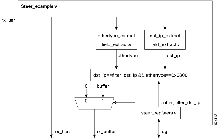
Steer Example
The devkit facilitates flow steering based on Ethernet frame fields using the libexanic API, which allocates DMA buffers with unique IDs. These IDs enable frame steering to specific buffers for applications like market data filtering. Included in the devkit is a flow steering example demonstrating IP packet steering to a designated buffer, ensuring only packets for a specified IP address are received. This setup can be customized for various applications.
The rx_buffer_host port selects the host receive buffer for incoming frames. The buffer ID must be set by the 15th data beat or at frame end, whichever is first, and remain constant through EOF+2 cycles. Additionally, setting all rx_buffer_host bits to 1 will drop the frame before it reaches any buffers. This setting should also occur by the 15th data beat or frame end. This example can be tested using filter.c or custom_filter_example. Usage for custom filter example:
./exanic-software/src/examples/devkit/custom-filter-example <device>:<port_number> <dst_ip> [expected_matches]
The usage for filter.c is as follows:
./exanic-software/testing/atf/src/filter <device>:<port> <dst_ip> <expected_num_matches>
Native loopback example
The native loopback example also demonstrates the latency of the SmartNIC MAC layer but loops back the frames received from the RX datapath on port 0 back out of port 0. This includes a CDC to transfer data from the receive domain to the transmit domain and 3 cycles of buffering to prevent TX underrun issues.
Multi preload tx example
The multi preload tx example in the devkit enables users to preload frames into FPGA memory and broadcast them simultaneously across multiple ports via a single register write.
Each port contains memory for 32 packets, 2048 bytes, and a separate metadata RAM that stores each packet's size as a 16-bit value. Packet buffers per port are independent, with each byte individually writable, allowing for updates to specific packet fields as needed.
To dispatch a packet, the software writes a 32-bit value to register address 0x0. This value includes <24-bit port mask> < 3 unused bits> <5-bit index> allowing selection from 32 preformatted packets. Different packets can be sent from different ports simultaneously using one register write.
The port mask specifies the ports for packet dispatch, e.g., a mask of 0x3 sends packets through ports 0 and 1. This setup also functions as a standard NIC, supporting usual packet send/receive operations via DMA.
Software for this design is available in the exanic-software repository under- examples/devkit/exanic-devkit-multi-preload-tx-example.c.
While the regular libexanic TX API also supports packet precaching, this design's unique feature is its ability to simultaneously send packets through multiple ports. For single-port operations, using the libexanic API is recommended.
Bridging example
The bridging example demonstrates the use of the frame mux for bridging of two ports on the card. Bridging involves looping back any received data on one port to the transmit datapath on another port. Note that this example will not work when a different line rate is used on each side of the bridge as there is no buffering added. The packet sent through port 0 will be received back through port 1 of the device.
Soft-responder example
The soft responder example demonstrates the latency of the SmartNIC MAC layer. It does this by sending a packet out of port 0 as soon as the start of frame is seen on the RX datapath of port 0. Note that this demo logic just sends a small frame of all 0xFF's (plus CRC).
Native Register Example
This is a minimal example of how to use the PCI register interface at BAR0. The memory interface at BAR2 is similar.
It is tested using the applications for read and write operations in exanic software.
For read operation: ./exanic-software/src/examples/devkit/exanic-devkit-register-read <device> <start_address> <end_address>
For write operation: ./exanic-software/src/examples/devkit/exanic-devkit-register-write <device> <start_address> <data>. This write will generate a packet out from port 0.
Native Spam Example
This is a simple packet generator for transmitting closely spaced frames of varying sizes. It can be configured by host software using the PCI register interface.
Software to drive the packet generator is available in the exanic-software repository at examples/devkit/spam-example.c. The usage for using the application is as follows:
$ ./exanic-software/src/examples/devkit/spam-example <device> \[-c num-frames\] \[-s min-size\] \[-S max-size\] \[-d dst-mac\] \[-g inter-frame-gap\] \[-b num-bursts\] \[-G inter-burst-gap\]
Example usage:
$ ./spam-example exanic1 -c 100 -s 60 -S 80 -g 0
This will send 100 frames with sizes 60 to 80 back-to-back.
Note that if the -c argument is not provided, it will send frames forever.
Ping example
The ping example in the devkit executes a hardware-timestamped ICMP echo request using source and destination IP addresses. It begins by checking the ARP table for a corresponding MAC address. If absent, it sends an ARP request and waits for a reply to update the table. Subsequently, it dispatches an ICMP echo request with a hardware timestamp and awaits a reply. If responses are delayed beyond 1 second for ICMP or ARP requests, an error message is sent to the host.
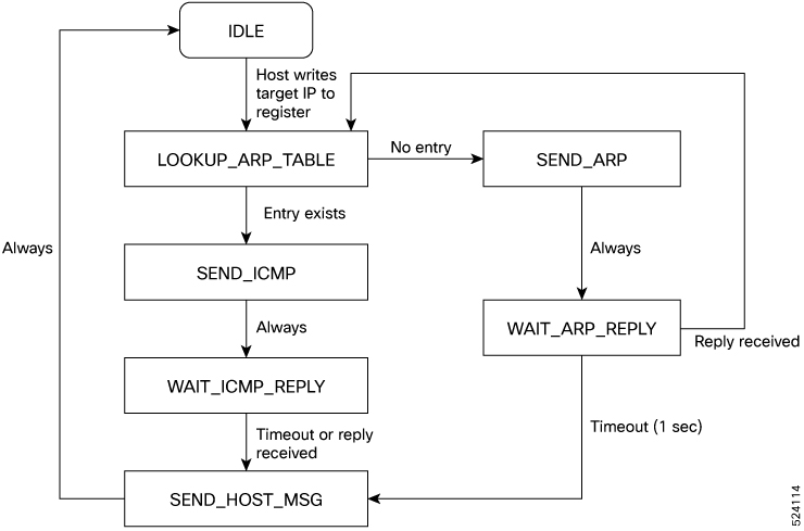
Key functionalities demonstrated include:
- Sending pre-defined packets with substituted field values, shown in the ARP and ICMP framegen modules.
- Parsing received packets and extracting data, as demonstrated by the ICMP echo parse and ARP parse modules.
- Communicating with software via custom frames sent through the DMA interface, handled by the custom framegen and frame mux modules.
- Basic lookup operations using the ARP table.
- Utilizing hardware timestamping capabilities.
To run the ping example, use: $ ./ping-example <device><dst-ip><src-ip>.
This will send ARP and ICMP packets originating from src-ip to the host at dst-ip.
Native early sof example
This is an example of using early_sof to trigger a packet. It does this by sending a packet out of port 0 as soon as the start of frame is seen on the RX datapath of port 0.
DDR4 example
This is a minimal example of using the ddr4 via the MIG interface. The read, write and reset operations to a DDR4 is carried out using the ddr4_example application provided in the exanic-software.
Usage for testing this example is:
$ ./exanic-software/src/examples/devkit/ddr4_example <device> <wr|rd|rst>
Native NIC example
This example mimics the behavior of a NIC. The MAC rx ports are connected to the host. The packets received through rx ports of MAC are sent to the host. For example, let's assume port 0 of testing device ‘device0’ is connected to port 0 of another device ‘device1’. If a packet is sent from port 0 of device1, the same packet will be received in capture at port 0 of device0.
NIC 256b host if example
This example is like the native NIC example, with the primary distinction being the RX host data width, which is 256 bits. The main objective of this example is to evaluate the FDK-Pro using the variant rxhostdatawidth256.
Host spam example
This is a simple example that rapidly sends packets of varying contents and lengths. Host spam example can be tested using the spam_example.c application provided in the exanic-software directory. The usage of spam_example.c is explained in the native_spam_example session.
Steer 256b example
The steer_256b_example is like the steer example. The primary distinction between both being the RX host data width, which is 256 bits. The main objective of this example is to evaluate the FDK-Pro using the variant rxhostdatawidth256. This example can be tested using filter.c or custom_filter_example as explained in the steer_example session.
Extra BARs example
This is a minimal example of how to use the additional register/memory spaces at BAR1 and BAR4. Software to drive this example is available in the exanic-software repository at examples/devkit/exanic-devkit-extra-bars-read.c and examples/devkit/exanic-devkit-extra-bars-write.c. For example, to read from offset 0 in BAR1 from a device at PCI address 01:00.0:
$ ./exanic-devkit-extra-bars-read/sys/bus/pci/devices/0000\\:01\\:00.0/resource1 0
Native trigger example
Native trigger example will trigger a packet out of port 1 when a packet is received at port 0. The packet received at port 0 should have first 32 bits are “0xffffffff”.
TCP trigger example
tcp_trigger_example is like native_trigger_example. It sends a TCP packet from port 1 on receiving an ethernet frame from port 0 if the first four bytes of the destination MAC address are 0xffffffff. ATE must be instantiated on port 1, that is, bit 1 in the TCP_ENABLES bitmask must be set.
Testbench and functional model
The SmartNIC development kit includes a complete model of all interfaces, located in the tb/ directory. The testbench files include:
- bench.v: Top-level harness for functional simulation.
- address_access.v: Simulates access to BAR0 and BAR2 memory spaces.
- control.v: Contains control tasks and generates the timestamp counter.
- dma_sim.v: Simulates the SmartNIC frame DMA interface, logs successful transfers, and flags errors.
- transmit_sim.v: Simulates the Ethernet transmit interface, logs successful transfers, and flags errors.
- frame_sim.v: Simulates host frame transmission or frames received from the wire.
- frame_sim_32bit.v: Functions similarly to frame_sim.v for a 32-bit datapath.
- test_cases.v: Holds user test cases, which can be added as needed.
- bench.prj: Project file for the Xilinx simulator, listing all simulation files. New files should be added here.
- start_sim.sh: Shell script to start the Xilinx simulator in console mode (use -gui switch for graphical mode).
To run the testbench:
$ ./start_sim.sh
This compiles the testbench and starts xsim in command-line mode. To run the simulation for 10 microseconds, enter at the xsim prompt:
% run 10us
Debugging with Vivado
Use the Xilinx Chipscope Pro Integrated Logic Analyzer (ILA) to debug FPGA designs through JTAG, detailed instructions and further documentation are available on Xilinx's website. The standard setup in the chipscope_example includes a Chipscope core that allows you to monitor specific signals, with additional configuration options available such as debug_clk. Signals for probing must be marked with (*mark_debug="true"*). Insertion of the ILA core into the design is handled by the debug.tcl script, which also specifies the capture clock.
Debugging can be performed via both local and remote JTAG connections.
Remote JTAG Connection (XVC Server)
Xilinx supports remote debugging through its Virtual Cable (XVC) protocol, allowing Vivado to connect to an FPGA via a server. Cisco offers a modified xvcServer utility for use with SmartNICs. To enable JTAG over XVC, include the JTAG=1 flag in the make command to incorporate necessary logic into the FDK. NOTE that the addition of this logic involves the MASTER_JTAG primitive, which disables the external JTAG interface. To regain external JTAG access, replace the FPGA image using exanic-fwupdate or the recovery button.
To operate the Cisco-modified xvcServer, which can be found in the examples/devkit directory of the exanic-software repository:
`$ sudo ./exanic-xvcserver exanic0
Waiting for connection on port 2542 …`
In Vivado, use the Hardware Manager as shown below or the open_hw Tcl command to manage hardware connections.
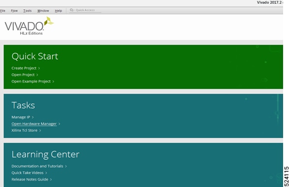
To start a hardware session in Vivado, either use the Tcl Console command connect_hw_server or select Open Hardware Manager from the Flow menu.
In the Tcl console, use the command:
open_hw_target -xvc_url 172.16.0.210:2542
This command connects to the machine running exanic-xvcserver. Once connected, exanic-xvcserver will acknowledge with "connection accepted," and the device (e.g., xcku035_0) should appear listed in Vivado.
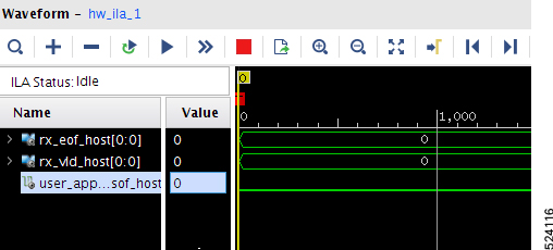
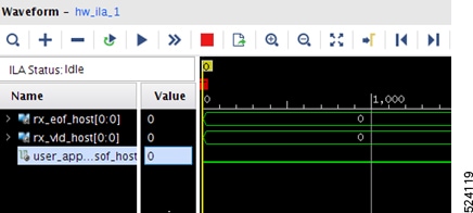
If your design includes an Integrated Logic Analyzer (ILA) core, go to the Trigger Setup window, click on the link to configure debug probes, and select the .ltx probe file located in the outputs/ directory.
Note
Cisco has seen instances where MIGs and ILA cores are not listed under the xcku035_0 device alongside SysMon. If you expect to see a core and don't, right click on the xcku035 device and select refresh.
Warning
Users should not attempt to configure the FPGA using the XVC server, as this relies on the FPGA to be configured to handle the JTAG shift instructions.
NOTE that exanic-xvcserver detects whether the JTAG logic has been inserted into the design and will not attempt to connect to an exanic without it.
Local JTAG Connection (Xilinx Platform Cable)
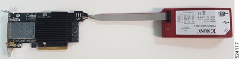
The Xilinx Platform Cable can be used for connecting via JTAG to the SmartNIC K3P-S (X25) and SmartNIC K3P-Q (X100). Connect one end of the Platform Cable to the machine running Vivado, and the other end to the SmartNIC.
The SmartNIC+ V5P has 2 methods for connecting to the device with a local JTAG connection.
Xilinx Platform Cable
Users can plug the standard 14 pin JTAG cable from a Xilinx Platform Cable or equivalent JTAG pod into the SmartNIC + V5P. Note that when this loom is inserted, connectivity from the USB JTAG circuitry to the FPGA is disabled.
USB JTAG
Users can plug a USB cable into a connector on the PCIe bracket of the SmartNIC+ V5P to gain JTAG access to the FPGA. Note that the USB JTAG interface and "14 way" interface cannot be used simultaneously. If a loom is connected between the 14 pin header and a Xilinx pod, the USB JTAG circuitry will be disconnected from the FPGA.
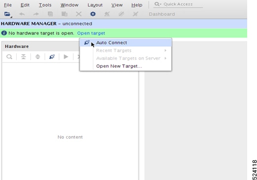
In Vivado, open the Hardware Manager. Start a Hardware Server session by entering connect_hw_server in the Tcl Console or selecting Open Hardware Manager from the Flow menu. Click Open Target and then AutoConnect; the FPGA (eg: xcku035_0) should now be visible. In the ILA core's Trigger Setup window, specify debug probes by selecting the .ltx probes file from the outputs/ directory.
Using JTAG to configure the FPGA
To configure the FPGA, the preferred method is using the exanic-fwupdate utility, though JTAG configuration is also feasible. By default, the SmartNIC reconfigures the FPGA upon host reset. To prevent this and retain a JTAG-loaded image, disable the automatic reboot by building the image with the NOREBOOT=1 flag:
make PLATFORM=v5p TARGET=native_loopback_example VARIANT=full NOREBOOT=1
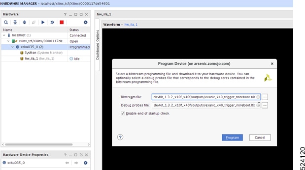
For JTAG connections, use the Xilinx Platform Cable. Do not configure the FPGA via the XVC server. To program the device, right-click on the Xilinx device in the software and select Program Device.
Booting from flash while JTAG cable is connected
Vivado may encounter issues booting from configuration flash when a JTAG cable is connected and the HW Manager is open, potentially leaving the FPGA unprogrammed. According to the Vivado Programming and Debugging User Guide (UG908) v2019.2, configuration failures can occur on power up if the Hardware Manager's polling and recover feature interrupts the Master mode configuration. To prevent this, disable updates to the configuration status registers by setting the following parameter in the Vivado Hardware Manager Tcl console:
set_param xicom.allow_cfgin_commands false
This setting will stop automatic updates for all devices in the JTAG chain, resulting in outdated values for registers like REGISTER.CONFIG_STATUS and REGISTER.BOOT_STATUS. To view correct and updated register values post-bootup, re-enable the parameter and refresh the device:
set_param xicom.allow_cfgin_commands true refresh_hw_device [get_hw_devices <device_name>
Alternatively, right-click the device in Vivado HW Manager and select Refresh Device.
Netlist variants
Cisco sets specific build options for the FDK-Pro at build time using "netlist variants," which are .edn netlists located in the src/ directory for each variant. Users select a variant by setting the variant flag during the make process. For example:
$ make PLATFORM=v5p TARGET=native_loopback_example VARIANT=full_fastmac
Key netlist variants include:
- full: Default build for 10G only.
- full_multirate: Supports 100M/1G and 10G, adds 1 extra cycle of latency.
- full_multirate_extrarxreg: Includes an additional pipeline stage in the RX MAC to improve timing.
- full_fastmac: Features an extra fast MAC, reducing latency by 3-6ns.
Note: Full refers to license validation, the netlist requires a full license. All other substrings of the netlist name (excluding the substring referring to the platform itself) refer to features of the PCS logic.
Note
Currently 100M/1G is only enabled for the first lane of each physical connector on a SmartNIC, when using a multirate variant. This means that 100M/1G support will only be enabled on port 0 and 4 of the SmartNIC+ V5P and SmartNIC K3P-Q (X100). The SmartNIC K3P-S (X25) can support 100M/1G on both physical ports if using a multirate variant.
Ports which do not have 100M/1G enabled can only operate at 10G.
Recovery image
All SmartNICs include a recovery flash image for rectifying corrupt flash situations. To enter recovery mode, hold the 'recovery' button on the card during host system reboot. Indicator of recovery mode is an alternating amber link lights on the SmartNIC+ V5P. Use the exanic-fwupdate utility to overwrite the corrupt image in this mode.
Remote recovery procedure
If physical access to a SmartNIC is unavailable for standard recovery, remote recovery via Vivado and JTAG is possible under these conditions:
- The SmartNIC must be connected via JTAG.
- The currently programmed image should not have been built with JTAG=1.
Remote Recovery Steps:
- Connect to the FPGA in Vivado using JTAG.
- Right-click the FPGA device and select "Add configuration memory device". Choose the appropriate memory part for your SmartNIC.
- When prompted by Vivado, select a known-good .mcs file for programming the memory, such as a build from native_nic_example.
- Right-click the FPGA device and choose "Boot from Configuration Memory Device" to program the FPGA with the newly written flash image.
- Before rebooting, execute the command set_param xicom.allow_cfgin_commands false in the Tcl console to prevent issues with the FPGA coming up unprogrammed upon reboot (see "Booting from flash while JTAG cable is connected").
- Reboot the host.
Following these steps will enable remote recovery of the SmartNIC through Vivado.
NIC Flash Memory Part Numbers
| NIC | Flash Part Number | Config |
|---|---|---|
| Cisco Nexus SmartNIC K3P-S (formerly X25) | S29GL256P11FFIV20 | NOR BPI x16 |
| Cisco Nexus SmartNIC K3P-Q (formerly X100) | MT25QU128ABA1EW7-0SIT | QSPI |
| Cisco Nexus SmartNIC V5P | MT28EW01GABA1LPC-0SIT | NOR BPI x16 |
Supporting Platforms
Platforms which are currently supported:
- V5P
- X100
- X25
 Feedback